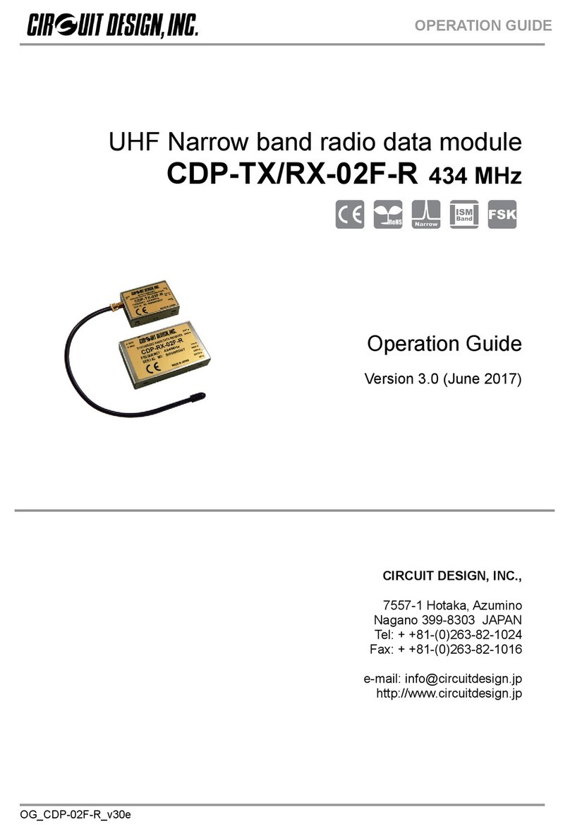
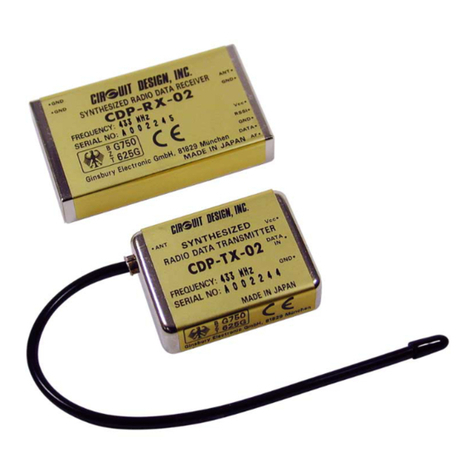
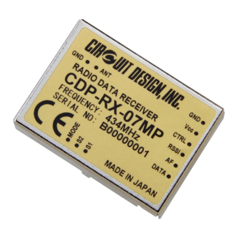
CIRCUIT DESIGN WA-TX-03S User manual

OG_WA-03S_V10e
OPERATION GUIDE
UHF Wireless Audio Module
WA-TX-03S / WA-RX-03S
Operation Guide
Version 1.0 (July 2017)
CIRCUIT DESIGN, INC.,
7557-1 Hotaka, Azumino-city
Nagano 399-8303 JAPAN
Tel: + +81-(0)263-82-1024
Fax: + +81-(0)263-82-1016
e-mail: info@circuitdesign.jp
http://www.circuitdesign.jp

OG_WA-03S_V10e Circuit Design, Inc.
2
OPERATION GUIDE
CONTENTS
GENERAL DESCRIPTION ................................................................3
FEATURES .......................................................................................3
APPLICATION ...................................................................................3
SPECIFICATION ...............................................................................4
TERMINAL DESCRIPTION ...............................................................5
CHANNEL TABLE .............................................................................7
REMARKS FOR INTEGRATION OF THE RECEIVER ANTENNA ....7
CONNECTION DIAGRAM .................................................................8
DIMENSIONS .................................................................................10
REFERENCE DATA.........................................................................12

OG_WA-03S_V10e Circuit Design, Inc.
3
OPERATION GUIDE
GENERAL DESCRIPTION
The WA-TX-03S / WA-RX-03S are 15ch multichannel audio modules that operate in
the European harmonized 863 - 865 MHz band. In addition to offering a frequency
range sufficient for voice transmission, the compander noise reduction system has a
wide dynamic range, enabling transmission of clear audio signals.
As embedded devices, they include nearly all the parts necessary for audio
transmission in a small shielding case, making it possible to develop audio
transmission equipment in a short time.
FEATURES
863 – 865 MHz European Audio band
15 channels, 125 kHz steps
90 dB dynamic range with built in noise reduction system
50 Hz - 13 kHz audio response
Low power operation
Adjustable mute level
Small size for embedding in user equipment
RED compliant
RoHS compliant
APPLICATIONS
Audio guiding in museums
Tour guide systems
Wireless conference systems
Wireless microphone systems for amateur users
Various audio transmissions
Voice monitoring

OG_WA-03S_V10e Circuit Design, Inc.
4
OPERATION GUIDE
SPECIFICATION
Common
Items Specification Remarks
Compatible standard EN 301 357 RE Directive
Frequency range 863.125 – 864.875 MHz
Number of channels 15 125 kHz step
Emission class F3E
Operating distance 50 m Line-of-sight
S/N ratio 90 dB or more W/IHF-A Filter
Audio frequency response 50 Hz-13 kHz +/-3.5 dB
T.H.D 2 % @AF 1kHz, Δf = 20kHz
Emphasis 50 us
Operating temperature range 0 to 50 °C
WA-TX-03S (Transmitter)
Items Specification Remarks
Oscillation type Crystal based PLL oscillation
RF power 5 mW / 10 mW (e.r.p)
Frequency stability +/- 15 kHz
Noise reduction Compander
Spurious emission 1 uW max.
Deviation 20 kHz 1 kHz @ -25 dBv
AF input level - 113 to -13 dBv 1 kHz
AF input impedance 12 kΩ or more
Maximum DC input to AF input 7 V DC max
Supply voltage 4.2 to 6 V 3.6 to 7 V *1
Consumption current 5mW: 50 mA
10mW: 60 mA
STB(open): <1mA
Dimensions 36 x 26 x 8 mm Excluding protrusion
Weight 13 g
*1 Supply voltage: 3.6 to 7V – Possible operating range without meeting full specifications
WA-RX-03S (Receiver)
Items Specification Remarks
Receiver type Single super heterodyne
Local oscillator type Crystal based PLL oscillation
IF Frequency 10.7 MHz
Noise reduction system Expander
Receiver sensitivity 21 dBuV (- 92 dBm) S/N 55 dB
Squelch sensitivity Adjustable by external VR
AF output level - 10 dBv Δf = 20 kHz
AF output impedance 20 kΩ or less
Supply voltage 3 to 5 V
Consumption current 45 mA
Dimensions 36 x 26 x 8 mm Excluding protrusion
Weight 13 g
*0 dBv=0.775 V * The data was taken at 25 C unless otherwise specified

OG_WA-03S_V10e Circuit Design, Inc.
5
OPERATION GUIDE
TERMINAL DESCRIPTION
WA-TX-03S transmitter module
No. Name I/O Description Equivalent circuit
1 UNA O
LED terminal for unavailable channels.
The terminal is high when any channel
outside CH 1 to 15 is selected.
LED can be powered directly
2 SW0 I Transmitter channel setting terminal
Select channel within 15 programmed
channels
Refer to “Channel table”
SW0 to SW3 are disabled when
STB=H(open).
3 SW1 I
4 SW2 I
5 SW3 I
6 NC -
7 SW5 I
H(open): 5mW
L(GND): 10mW
Power setting is enabled when the module
newly starts transmitting.
SW5 is disabled when STB=H(open).
8 STB I
Terminal for stand-by with power off delay
Set to High(open) to enter standby.
Set to ground when transmitting.
9 AF I Audio signal input terminal
Audio input signal level -113 dBv to -13 dBv
10 VCC I
Power supply (+) terminal
Voltage range is DC 4.2 to 6 V
A power source without ripple noise should
be used.
A protection diode for reverse connection is
provided in the circuit.
11 ANT O
Antenna terminal (RF output)
50 Ω impedance
12 GND I
GND terminal
The ground is for the power supply and
antenna radial.
Connect it to a wide ground plane for efficient
antenna emissions and stable operation.
-
+12kΩ 10uF Terminal
3V
*SW0-3&SW5: 3V when STB=L(GND)
*STB: always 3V
*
*

OG_WA-03S_V10e Circuit Design, Inc.
6
OPERATION GUIDE
WA-RX-03S receiver module
CN1
No. Name I/O Description Equivalent circuit
1 CON I
Terminal for adjustment of mute level.
Connect a 10 to 20 kΩ VR to the terminal for
mute level adjustment.
The mute level is the threshold level of the
received signal field strength so as not to
output the received signal below the threshold
level.
2 LED O
MUTE LED terminal
The terminal is high when mute is in operation.
It is low when the AF signal is output, so that
the LED connecting the terminal works as an
AF output indicator showing the AF output
status.
The terminal is an open collector and is
connected to a 220Ω resistor (Max 10mA).
3 UNA O
LED terminal for unavailable channels.
The terminal is high when any channel other
than CH 1 to 15 is selected.
The LED can be powered directly
4 VCC I
Power supply (+) terminal
The voltage range is DC 3.0 to 5 V
A power source without ripple noise should be
used.
Be sure to connect it with the correct polarity.
To maintain a lower voltage, a protection diode
is not provided in the circuit.
5 AF O
Audio output terminal
Output impedance is 20 kΩ.
Connection to a low input impedance interface
will decrease the output level.
Maximum output level is –10 dBv
When an audio amplifier is used, if the
amplified output is distorted by the MIC input,
insert an attenuator.
6 GND I
GND terminal
The ground is for the power supply and
antenna radial.
Connect it to a wide ground plane for stable
operation.
7 ANT I Antenna terminal (RF input).
50 Ω impedance

OG_WA-03S_V10e Circuit Design, Inc.
7
OPERATION GUIDE
CN2
No. Name I/O Description Equivalent circuit
1 SW0 I
Receiver channel setting terminal
Selects a channel within 15 programmed
channels
Refer to “Channel table”
2 SW1 I
3 SW2 I
4 SW3 I
5 NC -
6 NC -
CHANNEL TABLE
CH TX/RX frequency SW0 SW1 SW2 SW3
0 Unavailable H H H H
1 863.125 L H H H
2 863.250 H L H H
3 863.375 L L H H
4 863.500 H H L H
5 863.625 L H L H
6 863.750 H L L H
7 863.875 L L L H
8 864.000 H H H L
9 864.125 L H H L
10 864.250 H L H L
11 864.375 L L H L
12 864.500 H H L L
13 864.625 L H L L
14 864.750 H LLL
15 864.875 LLLL
L = GND
Remarks for integration of the receiver antenna
Please pay due attention to the design of the antenna ground plane based on the general design theory.
Locate the antenna in a place where there are no objects between TX and RX and that is visible from
the transmitter antenna. If a PCB pattern line is used for connection between the antenna terminal and
the antenna you choose, please secure the following pattern width.
PCB thickness (mm) 0.8 1 1.2 1.6
Pattern width (mm) 1.3 1.4 1.7 2.7
(The example above shows a case where a G10 double-sided PCB is used.)

OG_WA-03S_V10e Circuit Design, Inc.
8
OPERATION GUIDE
CONNECTION EXAMPLE (WA-TX-03S)

OG_WA-03S_V10e Circuit Design, Inc.
9
OPERATION GUIDE
CONNECTION EXAMPLE (WA-RX-03S)

OG_WA-03S_V10e Circuit Design, Inc.
10
OPERATION GUIDE
DIMENSION WA-TX-03S
Reference hole position (Top view)

OG_WA-03S_V10e Circuit Design, Inc.
11
OPERATION GUIDE
DIMENSION WA-RX-03S
Reference hole position (Top view)

OG_WA-03S_V10e Circuit Design, Inc.
12
OPERATION GUIDE
REFERENCE DATA
WA-TX-03S operation timing with STB switching
Transmission start (STB: H -> L)
Actual measurement value
Transmission halt (STB: L -> H)
Actual measurement value
386 ms
486 ms
649 ms
RF:ON Transmission starts with low RF power
RF POWER: ON Transmission with the set RF power
AF: ON Modulation starts
Cumulative
time
100 ms
163 ms
5 ms
49 ms
91 ms
Cumulative
time
AF: OFF Modulation stops
RF POWER: OFF Switched down to low RF power
RF:OFF RF power stops
44 ms
42 ms

OG_WA-03S_V10e Circuit Design, Inc.
13
OPERATION GUIDE
WA-TX-03 operation timing with channel switching
When switched to another channel
Actual measurement value
When switched from another channel
Actual measurement value
7 ms
51 ms
165 ms
Cumulative
time
AF: OFF Modulation stops
RF POWER: OFF Switched down to low RF power
RF:OFF RF power stops
44 ms
114 ms
508 ms
608 ms
648 ms
Cumulative
time
RF:ON Transmission starts with low RF power 100 ms
RF POWER: ON Transmission with the set RF power 40 ms
AF: ON Modulation starts

OG_WA-03S_V10e Circuit Design, Inc.
14
OPERATION GUIDE
Regulatory Compliance Information
Declaration of Conformity
Hereby, Circuit Design, Inc. declares that the WA-TX-03S and WA-RX-03S are in compliance with RE Directive
(2014/53/EU).
The full text of the EU Declaration of Conformity is available at www.circuitdesign.jp.
Cautions related to regulatory compliance when embedding WA-TX-03S/WA-RX-03S
1. Output power of the WA-TX-03S
EN 301 357 defines the equipment covered by its standard and the output power limits depend on the
equipment type.
The WA-TX-03S meets the output power limits allowed for all equipment types except for “in-vehicle
cordless” and “personal cordless”. If the WA-TX-03S is used for “in-vehicle cordless” or “personal cordless”
equipment, the manufacturer is required to design the final product within the specified output power limit
and to perform the conformity assessment of the final product to EN 301 357.
2. Antenna for the WA-TX-03S
The WA-TX-03S is supplied without a dedicated antenna.
The conformity assessment of the WA-TX-03S was performed using Circuit Design’s evaluation board and
antenna (1/4 lambda lead antenna). We recommend that you use our standard antenna (ANT-LEA-02 or
ANT-RIG-02), or an antenna with equivalent characteristics and performance. For details about our
evaluation boards and antennas, refer to www.circuitdesign.jp or contact us. If you use an antenna other
than the recommended antenna, further radio conformity assessment may be required.
3. Supply voltage of the WA-TX-03S
The WA-TX-03S should be used within the specified voltage range (4.2 V to 6.0 V).
4. Enclosure
To fulfill the requirements of EMC and safety requirements, the WA-TX-03S and the WA-RX-03S should be
mounted on the circuit boards of the final products and must be enclosed in the cases of the final products.
No surface of the WA-TX-03S and the WA-RX-03S should be exposed.
5. Cordless audio transmitter shutoff
The WA-TX-03S does not have the automatic transmitter shutoff function in the module. The manufacturer
of the final product is required to design the final product to have such function in accordance with EN 301
357.
Conformity assessment of the final product
The manufacturer of the final system needs to conduct full EMC testing in the final configuration and also ensure
the final product fulfills the safety requirements and is also responsible for the conformity assessment procedures
of the final product in accordance with the RE Directive.

OG_WA-03S_V10e Circuit Design, Inc.
15
OPERATION GUIDE
Important notice
Customers are advised to consult with Circuit Design sales representatives before ordering.
Circuit Design believes the provided information is accurate and reliable. However, Circuit Design reserves the
right to make changes to this product without notice.
Circuit Design products are neither designed nor intended for use in life support applications where malfunction
can reasonably be expected to result in significant personal injury to the user. Any use of Circuit Design
products in such safety-critical applications is understood to be fully at the risk of the customer and the
customer must fully indemnify Circuit Design, Inc for any damages resulting from any improper use.
As the radio module communicates using electronic radio waves, there are cases where transmission will be
temporarily cut off due to the surrounding environment and method of usage. The manufacturer is exempt from
all responsibility relating to resulting harm to personnel or equipment and other secondary damage.
The manufacturer is exempt from all responsibility relating to secondary damage resulting from the operation,
performance and reliability of equipment connected to the radio module.
Copyright
All rights in this operation guide are owned by Circuit Design, Inc. No part of this document may be copied or
distributed in part or in whole without the prior written consent of Circuit Design, Inc.
Cautions
Do not use the equipment within the vicinity of devices that may malfunction as a result of electronic radio waves
from the radio module.
Communication performance will be affected by the surrounding environment, so communication tests should be
carried out before actual use.
Ensure that the power supply for the radio module is within the specified rating. Short circuits and reverse
connections may result in overheating and damage and must be avoided at all costs.
Ensure that the power supply has been switched off before attempting any wiring work.
The case is connected to the GND terminal of the internal circuit, so do not make contact between the '+' side of
the power supply terminal and the case.
When batteries are used as the power source, avoid short circuits, recharging, dismantling, and pressure.
Failure to observe this caution may result in the outbreak of fire, overheating and damage to the equipment.
Remove the batteries when the equipment is not to be used for a long period of time. Failure to observe this
caution may result in battery leaks and damage to the equipment.
Do not use this equipment in vehicles with the windows closed, in locations where it is subject to direct sunlight,
or in locations with extremely high humidity.
The radio module is neither waterproof nor splash proof. Ensure that it is not splashed with soot or water. Do not
use the equipment if water or other foreign matter has entered the case.
Do not drop the radio module or otherwise subject it to strong shocks.
Do not subject the equipment to condensation (including moving it from cold locations to locations with a
significant increase in temperature.)
Do not use the equipment in locations where it is likely to be affected by acid, alkalis, organic agents or corrosive
gas.
Do not bend or break the antenna. Metallic objects placed in the vicinity of the antenna will have a great effect
on communication performance. As far as possible, ensure that the equipment is placed well away from metallic
objects.
The GND for the radio module will also affect communication performance. If possible, ensure that the case
GND and the circuit GND are connected to a large GND pattern.
Warnings
Do not take a part or modify the equipment.
Do not remove the product label (the label attached to the upper surface of the module.) Using a module from
which the label has been removed is prohibited.
Copyright 2017, Circuit Design, Inc.

OG_WA-03S_V10e Circuit Design, Inc.
16
OPERATION GUIDE
REVISION HISTORY
Version Date Description Remark
0.9 Feb.2017 Preliminary
1.0 July 2017 Regulatory information added
This manual suits for next models
1
Table of contents
Other CIRCUIT DESIGN Control Unit manuals
Popular Control Unit manuals by other brands

M-system
M-system R7L-EC16B instruction manual

Emerson
Emerson ANDERSON GREENWOOD WHESSOE 4110A Installation, operation and maintenance instructions

MX
MX Atmos Traditional Fitting instructions

Pro Control
Pro Control Pro.relay.4 Quick reference guide

INOXPA
INOXPA INNOVA T Installation, service and maintenance instructions

Heidolph
Heidolph Hei-VOLUME Distimatic Pro operating instructions