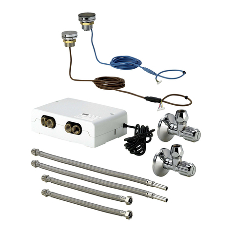
Viega 8655.11 User manual

For WC flush plates for Prevista electronic
Model Year built:
8655.11 from 03/2019
en_INT
Accessory set electronic
Instructions for Use

Accessory set electronic 2 from 23

Table of contents
1About these instructions for use 4
1.1 Target groups 4
1.2 Labelling of notes 4
1.3 About this translated version 5
2Product information 6
2.1 Standards and regulations 6
2.2 Safety advice 6
2.3 Intended use 6
2.3.1 Areas of use 6
2.4 Product description 7
2.4.1 Overview 7
2.4.2 Technical data 7
2.5 Accessories 8
3Handling 9
3.1 Assembly information 9
3.1.1 Mounting conditions 9
3.1.2 Required material and tools 10
3.2 Assembly 10
3.2.1 Setting the flush 10
3.2.2 Mounting with flush plate in front position 13
3.2.3 Mounting with flush plate in top position 18
3.3 Disposal 23
Table of contents
Accessory set electronic 3 from 23

1 About these instructions for use
Trade mark rights exist for this document; for further information, go to
viega.com/legal.
1.1 Target groups
The information in this instruction manual is directed at the following
groups of people:
nHeating and sanitary professionals and trained personnel
nQualified electricians
Individuals without the abovementioned training or qualification are not
permitted to mount, install and, if required, maintain this product. This
restriction does not extend to possible operating instructions.
The installation of Viega products must take place in accordance with
the general rules of engineering and the Viega instructions for use.
1.2 Labelling of notes
Warning and advisory texts are set aside from the remainder of the text
and are labelled with the relevant pictographs.
DANGER!
This symbol warns of possible life-threatening injury.
WARNING!
This symbol warns of possible serious injury.
CAUTION!
This symbol warns of possible injury.
NOTICE!
This symbol warns of possible damage to property.
This symbol gives additional information and hints.
About these instructions for use
Accessory set electronic 4 from 23

1.3 About this translated version
This instruction for use contains important information about the choice
of product or system, assembly and commissioning as well as intended
use and, if required, maintenance measures. The information about the
products, their properties and application technology are based on the
current standards in Europe (e.g. EN) and/or in Germany
(e.g. DIN/DVGW).
Some passages in the text may refer to technical codes in Europe/
Germany. These should serve as recommendations in the absence of
corresponding national regulations. The relevant national laws, stand‐
ards, regulations, directives and other technical provisions take priority
over the German/European directives specified in this manual: The
information herein is not binding for other countries and regions; as said
above, they should be understood as a recommendation.
About these instructions for use
Accessory set electronic 5 from 23

2 Product information
2.1 Standards and regulations
The following standards and regulations apply to Germany / Europe and
are provided as a support feature.
Regulations from section: Fields of application / Mounting conditions
Scope / Notice Regulations applicable in Ger‐
many
Protection area for installation of
the power pack in shower and
bath rooms
VDE 0100-701
Regulations from section: Technical data
Scope / Notice Regulations applicable in Ger‐
many
Electrical approvals EN 60950
Electrical approvals EN 60335
Electrical approvals EN 61558
2.2 Safety advice
DANGER!
Danger due to electrical current
An electric shock can lead to burns and serious injury and
even death.
– Work on the electrics may only be carried out by trained
electricians.
– Switch off the mains voltage before connecting the
power pack.
2.3 Intended use
2.3.1 Areas of use
The electronic accessory set is required for the power supply and the
control of electronic WC flush plates for Prevista.
Product information
Accessory set electronic 6 from 23

2.4 Product description
2.4.1 Overview
1 Control with motor
2 Power pack
3 Terminal
2.4.2 Technical data
Input (power pack) 100–240 V AC, 50–60 Hz, 180 mA
Output (power pack) 6.5 V DC, 800 mA
Electrical approvals see section
Ä
„Regulations from sec‐
tion: Technical data“ on page 6.
Electronics
Product information
Accessory set electronic 7 from 23

2.5 Accessories
installation set (model 8640.14)
The installation set contains a hollow wall socket to house the power
pack and an empty pipe to connect the cistern.
Extension cable (model 8352.690)
2 metre cable for the extension of the power supply.
Use a maximum of two extension cables with the power
pack (4.75 meter total length).
Connection cable (model 8570.55)
3-meter cable for external flush actuation with on-site with commercially
available buttons with closing function or potential-free contact (closing
period 350 ms)
Optional accessories
Product information
Accessory set electronic 8 from 23

3 Handling
3.1 Assembly information
3.1.1 Mounting conditions
The power pack should be mounted in an easily accessible place to
allow subsequent access.
Before beginning to clad, a concealed socket should be installed for the
power pack with empty pipe to the cistern (installation set
Ä
„Optional
accessories“ on page 8).
If necessary, the power pack cable can be extended to a length of
4.75 metres (two extension cables
Ä
„Optional accessories“ on page 8).
X1
X2
X3
Fig. 1: Installation position of the power pack
X1 max. 0.75 m
X2 max. 2.75 m with an extension cable (article number 628 505)
X3 max. 4.75 m with two extension cables (article number 628 505)
An extension of the mains supply by more than 5 metres can
lead to a situation in which the power is not sufficient to
actuate the flush.
Protected zone
Installation position of the power pack
Handling
Accessory set electronic 9 from 23

Fig. 2: Protected zones
According to the applicable regulations, installation of the power pack in
the protected zones 0 and 1 of shower rooms and bathrooms is not per‐
mitted, see
Ä
„Regulations from section: Fields of application /
Mounting conditions“ on page 6.
Viega recommends installing the power pack outside of the protected
zones 0–2.
3.1.2 Required material and tools
The following material is required for mounting:
nif necessary, empty pipe from power pack into the cistern
3.2 Assembly
3.2.1 Setting the flush
The smallest possible flush volume must be set at the drain
valve in the cistern.
The flush volume is set via the DIP switches of the control.
Material
Handling
Accessory set electronic 10 from 23

1 2 3 4 5 6 7 8
"#$
A Setting of the flush volume
B Interval of the Viega Hygiene+ function
C Setting the flush volume of the Viega Hygiene+ function
0 DIP switch position: OFF
1 DIP switch position: ON
The assignment of the DIP switches:
nSwitches 1-4 define the flush volume.
nSwitches 5-7 define the interval of the Viega Hygiene+ function.
nSwitch 8 defines the flush volume of the Viega Hygiene+ function.
NOTICE!
Damage due to moisture
Risk of damage to the control if moisture penetrates.
– Do not remove the protective cover of the DIP switches.
Handling
Accessory set electronic 11 from 23

Setting the flush volumes (A)
Program no. Large flush
volume (in litres)
Small flush
volume
(in litres)
Position of the
switches 1—4
1 2 3 4
Program 0
(factory set‐
ting)
6 3 0 0 0 0
Program 1 3.5 2 0 0 0 1
Program 2 4.5 2 0 0 1 0
Program 3 6 2 0 0 1 1
Program 4 7.5 2 0 1 0 0
Program 5 3.5 3 0 1 0 1
Program 6 4.5 3 0 1 1 0
Program 7 7.5 3 0 1 1 1
Program 8 4.5 4 1 0 0 0
Program 9 6 4 1 0 0 1
Program 10 7.5 4 1 0 1 0
Viega Enabling the Hygiene+ function and setting the intervals (B)
Interval (in hours) Position of switches 5—7
5 6 7
Switched off 0 0 0
1 0 0 1
12 0 1 0
24 0 1 1
72 1 0 0
168 1 0 1
Setting the flush volume of the Viega Hygiene+ function (C)
Flush volume (in litres) Position of switch 8
3 0
7.5 1
Handling
Accessory set electronic 12 from 23

3.2.2 Mounting with flush plate in front position
DANGER!
Danger due to electrical current
An electric shock can lead to burns and serious injury and
even death.
– Only allow electrical work to be carried out by qualified
electricians.
– Always de-energise the connection cable before work is
commenced.
Observation of the prescribed connection sequence is
required. The power supply must always be connected last,
to ensure that all of the connected components function.
Handling
Accessory set electronic 13 from 23

Requirements:
nA 230 V mains connection is available on site.
nThe installation position of the power pack complies with the require‐
ments in acc. with
Ä
Chapter 3.1.1 „Mounting conditions“
on page 9.
nThe connection cable is de-energised.
Remove the shaft cover.
Turn the cover plate lock 90° in anti-clockwise direction.
Remove the cover plate.
Remove the site protection.
Handling
Accessory set electronic 14 from 23

Put the power pack in place.
Remove approx. 1 cm of the insulation on the cables.
Push the cables into the terminals.
INFO! Use the cable feedthrough.
Route the connection cable from the power pack through the empty
pipe into the cistern.
Guide the connection cable out through the cistern.
Turn the cover plate 90°.
Place the control on the rear of the cover plate.
d
Handling
Accessory set electronic 15 from 23

Let the control engage in the mechanism.
Turn the cover plate 180°.
Connect the bow of the mechanism and the control with the eye.
Apply the silicon grease to all connections of the control.
d
Y
Handling
Accessory set electronic 16 from 23

Create the plug connection from power pack to control.
Guide the control cable forward through the right-hand opening of
the cover plate.
Insert the cover plate into the cistern.
Turn the cover plate lock by 90° in a clockwise direction.
Insert the shaft cover.
ðYou have mounted the control.
Handling
Accessory set electronic 17 from 23

3.2.3 Mounting with flush plate in top position
DANGER!
Danger due to electrical current
An electric shock can lead to burns and serious injury and
even death.
– Only allow electrical work to be carried out by qualified
electricians.
– Always de-energise the connection cable before work is
commenced.
Observation of the prescribed connection sequence is
required. The power supply must always be connected last,
to ensure that all of the connected components function.
Handling
Accessory set electronic 18 from 23

Requirements:
nA 230 V mains connection is available on site.
nThe installation position of the power pack complies with the require‐
ments in acc. with
Ä
Chapter 3.1.1 „Mounting conditions“
on page 9.
nThe connection cable is de-energised.
Remove the shaft cover.
INFO! In the description of the following steps, the cistern is
shown in top view.
Turn the cover plate lock 90° in anti-clockwise direction.
Remove the cover plate.
Handling
Accessory set electronic 19 from 23

Remove the site protection.
Put the power pack in place.
Remove approx. 1 cm of the insulation on the cables.
Push the cables into the terminals.
INFO! Use the cable feedthrough.
Route the connection cable from the power pack through the empty
pipe into the cistern.
Guide the connection cable out through the cistern.
Remove the mechanism.
Handling
Accessory set electronic 20 from 23
Other manuals for 8655.11
1
Table of contents
Other Viega Control Unit manuals

Viega
Viega 1252.1 User manual

Viega
Viega 8133.3 User manual

Viega
Viega 8461.18 User manual

Viega
Viega PureFlow Crimp Instruction sheet

Viega
Viega Easytop 2282 User manual

Viega
Viega Easytop XL Series User manual
Viega
Viega 1247.4 User manual

Viega
Viega Easytop 2170 User manual

Viega
Viega Easytop 2275.10 User manual

Viega
Viega 2337.5 User manual

Viega
Viega 8310.76 User manual

Viega
Viega 8332.3 User manual

Viega
Viega PureFlow 2842.3ZL Instruction sheet

Viega
Viega 56160 Instruction sheet

Viega
Viega ProPress 22074 Instruction sheet

Viega
Viega Grundfix 4987 User manual
Viega
Viega 2235.2 User manual

Viega
Viega 2281.7 User manual
Viega
Viega 2243.10 User manual

Viega
Viega 2275.2 User manual