CircuPool EDGE Series User manual

CircuPool Help Guides:
EDGE Series
1
WARNING –Always make sure the input power is completely disconnected before attempting any troubleshooting procedures.
All troubleshooting should be done by a qualified professional.
EDGE Series
Troubleshooting Guide
Table of contents:
Water Chemistry:
Requirements & Adding Salt pg.2
Langelier Saturation Index pg.3
How to Clean the Electrolytic Cell pg.4
Control Module Reprogramming pg.5
Low Chlorine Level in Pool pg.6
Troubleshooting Warning Lights:
Water Flow pg.9
Low Salt pg.10
Check Cell (Solid) pg.10
Check Cell (Flashing) pg.11
No Power on Display pg.11
How to Diagnose System Error Codes pg.12
Troubleshooting Error Codes:
System Error 1 pg.13
System Error 2 pg.15
System Error 3 pg.17
System Error 4-7 pg.18
Quick Reference pg.19
The complete EDGE manual is always available at Circupool.com:
https://www.circupool.com/Help-Guides-User-Guides_ep_41.html
WARNING
-
ALWAYS MAKE SURE THE INPUT POWER IS COMPLETELY DISCONNECTED BEFORE ATTEMPTING ANY
TROUBLESHOOTING PROCEDURES. ALL TROUBLESHOOTING SHOULD BE DONE BY A QUALIFIED PROFESSIONAL.
IMPORTANT
-REMEMBER THAT YOUR POOL IS COMPATIBLE WITH CHLORINE AND SHOCK AS NORMAL. IF YOUR POOL IS
EXPERIENCING TEMPORARY LOSS OF CHLORINE OR OTHER DIFFICULTIES, ADD SANITIZER AS NEEDED TO MAINTAIN THE POOL.

CircuPool Help Guides:
EDGE Series
2
WARNING –Always make sure the input power is completely disconnected before attempting any troubleshooting procedures.
All troubleshooting should be done by a qualified professional.
Water Chemistry –Chemistry Requirements & Adding Salt
Standard ranges for pool chemistry. These levels reflect national standards; it is necessary to be within these ranges in order to have
effective water sanitation.
Free Available Chlorine 1.0 - 3.0 ppm
Salinity 3000 - 4500 ppm
pH 7.2 - 7.8 (7.5 best)
Stabilizer (Cyanuric Acid) 30 - 50 ppm
Total Alkalinity 80 - 120 ppm
Calcium Hardness 200 - 400 ppm
Saturation Index -0.2 to +0.2 (0 best)
Phosphates 0 to 100 ppb (0 best)
Nitrates 0 to 10 ppm (0 best)
Iron 0
Copper 0
Other metals 0
Ammonia 0
TDS <1200
Adding Salt. This system is designed to operate most efficiently when maintained between a 3500 and 4000 ppm. When adding large
quantities of salt, independently test the existing salt level and add in portions, retesting at each stage.
IMPORTANT: Before adding salt at any time, ALWAYS perform an independent water test to measure pre-existing salt levels.
The chart below indicates how much salt is required based on the volume of the pool and the current salt level. Use only salt that is
99% pure sodium chloride.
If your pool holds this many gallons…

CircuPool Help Guides:
EDGE Series
3
WARNING –Always make sure the input power is completely disconnected before attempting any troubleshooting procedures.
All troubleshooting should be done by a qualified professional.
WATER CHEMISTRY -LANGELIER SATURATION INDEX (LSI)
LSI is a measurement of the water’s ability to absorb and hold solids in a solution. It is important to know that the scale on which LSI
is measured is very narrow, meaning that a small change can indicate a significant difference in your pool. Like pH, the LSI value is
logarithmic, meaning that a difference of 1.0 equates to a difference of ten times in reality. A Saturation Index of -2.0 is ten times
more corrosive than an SI of –1.0. This is important, as many pool equipment manufacturers may not be able to warranty damage
caused by an out-of-balance LSI.
STEPS TO TAKE:
1. Obtain a complete water chemistry test from a pool store for the following items:
pH, Water Temperature, Alkalinity, Cyanuric Acid (Stabilizer), Calcium Hardness, Total Dissolved Solids
2. Go to the LSI Calculator at www.aquachek.com
a. Click on “Calculators”
b. Click on “Langelier Saturation Index”
c. Plug in your results and obtain your Saturation Index number.
3. Go to https://www.poolcalculator.com/ to balance your water accordingly.
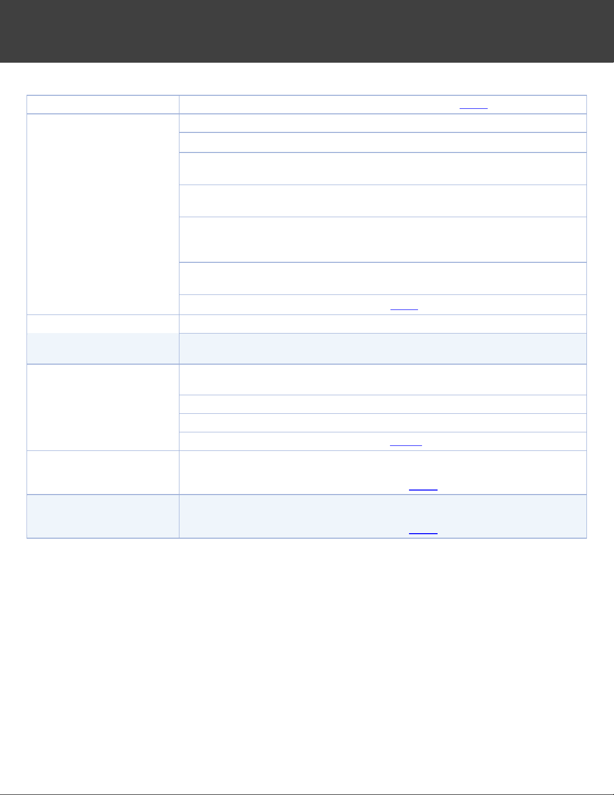
If LSI Index is between -0.2 and +0.2 pool water is Balanced. When pool water is balanced, it has no effect on the pool or equipment.
There are two values you can readily change to help improve your LSI value to get it into the optimum range: pH and Alkalinity level.
If LSI Index is less than -0.2 pool water is Corrosive. Pool water may cause etching, pitting, dissolving and staining of walls, grouting
and plumbing. It will also cause erosion to the titanium salt cell.
•As Stabilizer Increases, LSI Decreases
•As Total Dissolved Solids Increase, LSI Decreases
To raise your LSI value, you should first balance the calcium hardness in the pool. It needs to be between 200-400 PPM at all times. If
the calcium hardness is in the correct range, add sodium bicarbonate or baking soda. Consult the calculator at
www.poolcalculator.com to determine the target Alkalinity value (recommended range is 80-120ppm; however, you may find that a
level lower than 80 may be ideal for a balanced LSI value).
If LSI Index is greater than +0.2 pool water is Scale Forming. Pool water may deposit excess minerals on the pool and equipment.
Scale generally appears as white or lightly colored rough blotches on the pool walls. It also adheres to other objects in the pool, piping
and filter system. This will cause calcium deposits to rapidly form on the titanium salt cell. Scale can restrict water flow, shortening
filter runs and reducing filtration efficiency.
•As Temperature Increases LSI Increases
•As Total Alkalinity Increases LSI Increases
•As pH Increases, LSI Increases
•As Calcium Hardness Increases, LSI Increases
To lower your LSI value, you should first consider adding muriatic acid (can be found in pool supply stores), as it is more difficult to
lower Calcium Hardness and especially temperature. Consult the calculator to determine the target pH value.

CircuPool Help Guides:
EDGE Series
4
WARNING –Always make sure the input power is completely disconnected before attempting any troubleshooting procedures.
All troubleshooting should be done by a qualified professional.
How to Clean the Electrolytic Cell
IMPORTANT: Using gloves and eye protection duringthisprocess is recommended. Always add acid to the water, never waterto the acid.
Always work in a well-ventilated area.Splashingor spilling acid can cause severe personalinjury and/or property damage. The Electrolytic
Cell has the self-cleaning Reverse Polarity feature built-in, which prevents mineral deposits from forming rapidly. However, the Cell
may eventually need to be manually cleaned. The frequency of mineral build-up is dependent upon the balance of the pool's water
chemistry, specifically the Saturation Index (see page 3).
In most circumstances, the Check Cell LED indicator will be illuminated solidly when the cell needs to be cleaned. Do not insert metal
or any hard objects inside the cell during cleaning, this will void the warranty. Follow these steps to clean the cell:
1. Turn all power to the filter system and salt system off. Close return line valves if applicable. Completely disconnect
the Cell Cord from the Control Module. Unscrew the two threaded collars at the inlet and outlet side of the cell, then
remove the cell from the return line.
2. Remove the o-ring on the “smaller” end of the cell.
3. Attach the Cleaning Cap (included with system at original purchase) to the other side of the cell (the “wider” end),
then orient the cell vertically with the Cap on bottom.
4. In a separate bucket, mix a solution of one part Muriatic Acid and five parts water, and pour the solution into the
top of the cell.
•Secure cell and let it soak until all mineral scaling has been dissolved.
•You will notice a fizzing or fogging effect inside the cell once the solution has made contact with the titanium
cell, this is normal. The solution should completely cover the titanium plates, and should usually be allowed
to soak for 10 minutes.
•Depending on the amount of scaling, a cell may need to be cleaned multiple times in a row. The cleaning
solution may stop fizzing because the acidity of the cleaning solution has been neutralized by the amount of
mineral scale, not because all of the scale has been removed.
5. Safely dispose of the solution by pouring it into the pool.
6. Flush out any remaining debris from the cell with a hose.
7. Put the o-ring back in place and re-install the cell in the pool plumbing.

CircuPool Help Guides:
EDGE Series
5
WARNING –Always make sure the input power is completely disconnected before attempting any troubleshooting procedures.
All troubleshooting should be done by a qualified professional.
Control Module Reprogramming
When installing a new cell of the same size –or –clearing the flashing Check Cell LED:
This procedure will reset the system’s internal count of production hours. This should be done in order to clear
the Check Cell light when flashing and any time a new cell (of the same size) is installed.
1. Press the On/Off switch to deactivate the Control Module. (Leaving power on at power source)
2. Hold down the chlorine Adjust button until the LED’s on the chlorine output power graph light up. Take
note of how many LED’s are displayed: 1 LED (EDGE15), 4 LEDs (EDGE25), or 8 LEDs (EDGE40).
3. Tap the Adjust button once, then let the Control Module sit until the lights turn off.
4. Hold down the Adjust button until the LED’s light back up on the chlorine output power graph.
5. Tap the Adjust button twice (confirm that the same number of LED’s are lit up as on Step #2 above), let
the Control Module sit until the lights turn off, then hit On/Off button to turn unit back ON.
6. Turn off power at the power source (breaker, timer, etc…) for about 30 seconds.
7. Turn power back on at the power source.
8. Allow the salt system and pump to run for at least 5 minutes to calibrate before shutting it off again.
When installing a new cell of a different size:
If a different size cell is to be used (ex: upgrading to a new Cell of a larger size), the Control Module needs to
be set in order to work correctly with the new Cell size. Follow these instructions to change the Control
Module to the correct Cell Type.
1. Press the On/Off switch to deactivate the Control Module. (Leaving power on at power source)
2. Hold down the chlorine Adjust button until the LED’s on the chlorine output power graph light up.
3. Press the chlorine Adjust button to set the Control Module to a EDGE15 (1 LED light displayed), EDGE25
(4 LED lights displayed), or EDGE40 (8 LED lights displayed).
4. Once desired size is chosen, let the Control Module sit until the lights turn off, then hit On/Off button
to turn unit back ON.
5. Turn off power at the power source (breaker, timer, etc…) for about 30 seconds.
6. Turn power back on at the power source.
7. Allow the salt system and pump to run for at least 5 minutes to calibrate before shutting it off again.

CircuPool Help Guides:
EDGE Series
6
WARNING –Always make sure the input power is completely disconnected before attempting any troubleshooting procedures.
All troubleshooting should be done by a qualified professional.
LOW CHLORINE LEVEL IN POOL
IMPORTANT: Measuring a low chlorine level does not indicate that your system is not working. Water chemistry and environmental
conditions are the #1 cause of a low chlorine level in a saltwater pool. The following steps will enable you to verify with certainty
whether or not your system is operational and creating chlorine. Following that, this help guide will help identify what may contributing
to the low chlorine level in the pool water.
Verifying that the system is operational
There are two variables involved in the generation of chlorine: salt and electricity. If there is salt in the water and power being sent to
the Electrolytic Cell, the system is generating chlorine normally. If the salt level is in question, independently test a water sample.
+ =.
Verifying Power is present in Cell
1. Ensure no Warning Lights are on (inhibiting Power in the cell)
oIs the Water Flow LED indicator illuminated? If it is, the system is not able to send power through the cell because
the Flow Sensor is not being triggered by the flow of water. See Page 9 for troubleshooting.
oIs the Check Cell or Low Salt LED indicator illuminated? If it is, the system is not able to send power through the cell
because of excess mineral build-up inside of the cell or improper salt levels. See Page 10 for troubleshooting.
oIs the System Error LED indicator illuminated solidly? If it is, the system is detecting an ongoing issue or critical fault
and has stopped sending power through the Cell. See troubleshooting beginning on Page 12.
2. Confirming Power in the Cell (measuring cell current)
oIf all warning lights are off, power is successfully able to pass through the cell. For further confirmation, the Control
Module has a built-in power meter that verifies that the full & normal amount of power is able to pass through the cell.
oTo verify the power being sent through the cell, turn the chlorine output setting up to 100% for diagnostic purposes.
To access the power reading, press and hold the BOOST button for three seconds to display the "Cell Current" reading
(Water Flow LED indicator will now be ON).
▪The power graph LED lights will begin to alternate back and forth with the Power (ON/OFF) LED light.
▪Count the number of chlorine level LED’s when the Power LED is on, and when the Power LED is off.
•Example: 5 chlorine level LED’s lit with the Power LED on, and 7 chlorine level LED’s lit with the
Power LED off = 5.7 cell amps
oAs long as you can confirm that there is a "Cell Current" reading (often 5-6 when turned up to 100%), the system is
successfully able to pass power through the Cell, and is operating normally and creating chlorine.
Summary: If salt is present above the minimum level of 3000 ppm, if the no warning lights are illuminated solidly, and if "Cell
Current" reads normal when the system is turned up to 100%, then the system is fully operational and creating chlorine
normally. If a low chlorine level persists after continued operation, see the next pages to troubleshoot common causes of
high chlorine demand.
IMPORTANT -REMEMBER THAT YOUR POOL IS COMPATIBLE WITH CHLORINE AND SHOCK AS NORMAL. IF YOUR POOL IS
EXPERIENCING TEMPORARY LOSS OF CHLORINE OR OTHER DIFFICULTIES, ADD SANITIZER AS NEEDED TO MAINTAIN THE POOL.
CHLORINE
PRODUCTION
salt
power

CircuPool Help Guides:
EDGE Series
7
WARNING –Always make sure the input power is completely disconnected before attempting any troubleshooting procedures.
All troubleshooting should be done by a qualified professional.
LOW CHLORINE LEVEL IN POOL (Continued)
Common Causes of High Chlorine Demand & Depleted Chlorine Levels
Examine the Water Chemistry (Also see Page 2):
•Water chemistry and environmental conditions are the #1 cause of a low chlorine level in a saltwater pool, as they cause chlorine
demand to rise above normal levels. High chlorine demand means that chlorine is being consumed quicker than it is being
replenished, resulting in the inability to measure the chlorine residual in the water. If operation has been verified (as described
on the previous page), a depleted chlorine level does not mean that the chlorine generator is not working, only that the chlorine
demand currently exceeds the rate of chlorine production.
•The ideal levels for a pool are:
Free Available Chlorine 1.0 - 3.0 ppm
Salinity 3000 - 4500 ppm
pH 7.2 - 7.8 (7.5 best)
Stabilizer (Cyanuric Acid) 30 - 50 ppm
Total Alkalinity 80 - 120 ppm
Calcium Hardness 200 - 400 ppm
Saturation Index -0.2 to +0.2 (0 best)
Phosphates 0 to 100 ppb (0 best)
Nitrates 0 to 10 ppm (0 best)
Iron 0
Copper 0
Other metals 0
Ammonia 0
The levels that are highlighted levels are the most common causes of high chlorine demand and depleted chlorine levels in
pools. Ensure that all three levels are being tested for and that their values are included on your chemistry report.
LOW or HIGH Chlorine Stabilizer (Cyanuric Acid, or CYA). The level must be within range, especially during the spring and
summer months. If there is not enough CYA in the pool, then your chlorine will not be protected from the sun and the
chlorine being produced by the salt system will be consumed once the sun hits the pool water. Up to 90% of the pool's
chlorine can be depleted within 2 hours without a sufficient level of chlorine stabilizer. Too much CYA makes CL ineffective.
Phosphates and Nitrates that are present in the pool will cause the chlorine demand to rise and/or will consume the chlorine
being made by the salt system (Also see page 4). Phosphates are very common. Any Phosphate level near or above 100 parts
per billion can greatly increase the chlorine demand in the pool. Any Phosphate level over 200 Part Per Billion will not only
consume your chlorine, it will also readily feed algae. To remove phosphates, use commercial grade Phosfree. When trying
to lower significant phosphate levels, phosphate products meant for weekly maintenance are usually not effective Nitrates
will also rapidly consume your chlorine. If the Nitrate level is high, it is often most effective to drain the pool and refill with
new water, being sure to add the necessary amount of salt back to the pool.
Lower salt levels can affect chlorine generation and cause the system to work inefficiently.
Other chemistry imbalances and the presence of metals, ammonia, and other impurities can cause high chlorine demand.

CircuPool Help Guides:
EDGE Series
8
WARNING –Always make sure the input power is completely disconnected before attempting any troubleshooting procedures.
All troubleshooting should be done by a qualified professional.
Common Causes of Low Chlorine Levels (Continued)
Insufficient Operation:
•Ensure input power- Is the salt system turning on and off with the pump as normal? Has the fuse / fuse reset button been tripped?
If so, see "No Power", page 11.
•Output Level - The percentage output level that you set tells the system how much of its maximum capacity to use in order to
create chlorine. If you are experiencing high chlorine demand, ensure that you have your system turned up to 100% output so
that it is doing as much as possible to compensate. Leave the system at 100% output until the pool is balanced again. Since every
pool operates differently and has a different level of chlorine demand, during normal operation there is not a standard percentage
level at which to set the output.
•Run time - When sized right, a chlorine generator can typically achieve sufficient chlorination when run on the filter pump's
normal schedule. However, every pool has different equipment and its operation is unique, and you may require (or choose) to
run the filter pump more or less than is standard. As a rule of thumb however, run your system one hour for every ten degrees of
ambient temperature in order to achieve both sufficient filtration and chlorination. Periods of high use, harsh environmental
conditions, or excessive chlorine demand may require extended run times. For example, running your system twice as long will
allow it to create twice as much chlorine.
•Cell Maintenance - Make sure the cell plates are clean and free from any debris. The Self-Cleaning feature minimizes the amount
of mineral deposits that will occur, but as with every salt system, the electrolytic cell should be cleaned periodically. If there are
any calcium deposits or debris that may have made it past the filter (hair, grass, etc...) which are causing the cell plates to bridge
together, clean the cell with one part muriatic acid and five parts water for 10 minutes. If the cell plates need to be cleaned the
Check Cell (Cell Maint.) light will most likely be illuminated.
•During initial startup (springtime / new pools) - When being opened, pools typically have much higher than normal chlorine
demand. In these circumstances a pool requires a large amount of sanitizer all at once, which means that it is often more effective
to add chlorine or shock as needed initially instead of waiting on the system to slowly reach "break-point" chlorination.

CircuPool Help Guides:
EDGE Series
9
WARNING –Always make sure the input power is completely disconnected before attempting any troubleshooting procedures.
All troubleshooting should be done by a qualified professional.
Water Flow –Error Light
This error light typically indicates the Flow Sensor is not being triggered
by water flow. This error light causes the Cell to stop generating
chlorine.
Troubleshooting:
•Verify that there is a proper cable connection between the Control Module and Flow Sensor
•Verify that the pump is on and running.
•Verify that you have proper water flow without a pocket of air in the Cell housing.
•Verify that water flow is sufficient to fully press the Flow Sensor paddle away from its resting center position. In case
you have a variable speed pump, increase flow until the LED turns off.
Additional Troubleshooting (turn off pump and salt system):
•Unscrew the Flow Sensor from the PVC tee-fitting. Make sure the paddle moves back and forth correctly. Does the
paddle move smoothly when pressed or is it stuck? Does it have proper tension to allow the paddle to snap back on
its own to the default position? If stuck, damaged, or if it lacks tension, replace Flow Sensor. If not, reinstall Flow
Sensor into PVC tee-fitting, being sure that the Flow Sensor points in the proper direction once screwed in.
•For further troubleshooting, you will need a small metal wire, paper clip, or other similar object to serve as a “jumper”
to complete the circuit.
•Disconnect the Flow Sensor cable connection to the
Control Module
•Put small jumper wire in the female connector pin
holes on the Control Module’s cable. Make sure the
wire is securely in both sides of the female
connections in order to complete the circuit.
•Turn on pump and salt system to see if the “Water
Flow” LED stays off.
▪If the “Water Flow” LED remains off, replace Flow Sensor.
▪If the “Water Flow” LED remains on, replace the Control Module.

CircuPool Help Guides:
EDGE Series
10
WARNING –Always make sure the input power is completely disconnected before attempting any troubleshooting procedures.
All troubleshooting should be done by a qualified professional.
Low Salt (Solid or Flashing) –Error Light
When this LED is illuminated, salt may need to be added to the pool.
Troubleshooting:
•The pool’s salinity level may be getting low. Independently measure salt level and adjust to 3500-4000ppm if needed.
•If the salinity level independently tests in range, the cell may be accumulating mineral scaling or other debris that
needs to be removed. Clean the cell according to the instructions on page 4.
•If the salt level is ideal and the cell has been thoroughly cleaned multiple times in a row, the cell plates may be partially
depleted and the cell is coming near to the end of its useable lifespan.
•Additional Troubleshooting: The Control Module is programmed to match the size of the Cell model. If a different size
Cell has been put on or if this setting may have been unintentionally changed, follow the Reprogramming instructions.
Check Cell (Solid) –Error Light
When this LED is illuminated, the cell may need to be cleaned.
Troubleshooting:
•Double check the pool’s salinity level. Independently measure salt level and adjust to 3500-4000ppm if needed.
•If the salinity level independently tests in range, the cell needs to be cleaned to remove mineral scaling or other debris.
Clean the cell according to the instructions on page 4. Inspect the cell after cleaning to make sure nothing is stuck
between the plates. Sometimes multiple cleanings in a row are required; mix a new batch of cleaning solution and let
it soak inside the cell. If “fizzing” still occurs, repeat the cleaning process with new solution each time until fizzing no
longer occurs when new solution has been added to the cell.
•If the salt level is ideal and the cell has been thoroughly cleaned multiple times in a row, the cell plates may be depleted
or damaged and the cell has reached the end of its useable lifespan. If damaged, inspect the cell for plates that are
damaged, deteriorated, pitted or physically worn. If so, this indicates corrosive water chemistry (low LSI) that needs
to be prevented through regularly ensuring proper water balance.
•Additional Troubleshooting:
•Is the pool losing prime and/or is low-speed pump operation causing air to accumulate in the Cell?
•Has the salt system been run without any pump operation? If the cell has a white milky coating and is no
longer clear, the Flow Sensor should also be checked for failure.
•Has a new Cell been installed after replacing a depleted Cell? Allow the system to run for at least 45
minutes and the “check cell” LED should go off.

CircuPool Help Guides:
EDGE Series
11
WARNING –Always make sure the input power is completely disconnected before attempting any troubleshooting procedures.
All troubleshooting should be done by a qualified professional.
Check Cell (Flashing) –Error Light
This LED may flash when the cell is nearing the end of its lifepsan.
Troubleshooting:
No troubleshooting is required. The Cell can continue to be used until a solid warnling light occurs, but enough operation
has occurred that you should consider purchasing a replacement cell. The flashing LED light can be cleared by following
the follow the Reprogramming instructions on page 5.
No Power on Display –Non-functional Control Module
Is the pump running? Are all breakers on? Have you verified power going into the unit? If these things are confirmed and
the system is not powering on or reacting, the Control Module must be replaced.

CircuPool Help Guides:
EDGE Series
12
WARNING –Always make sure the input power is completely disconnected before attempting any troubleshooting procedures.
All troubleshooting should be done by a qualified professional.
How to Diagnose System Error Codes
When the System Error indicator light is lit, perform the following diagnostic to identify the System Error code. The System Error
light MUST BE ILLUMINATED before testing.
If the SYSTEM ERROR LED is lit:
1. If unit is currently ON (if the LED above on/off is lit), tap the on/off button once to turn it OFF.
2. The unit will go OFF, but the System Error light will remain ON. To get the Error Code, count the number of LED
lights that are lit on the “chlorine power level”graph (anywhere from 1 to 7 will be lit).
3. This count is the System Error Code currently indicated. Proceed to the corresponding section for that System
Error code. In the example below, System Error code 2 is shown.
Example of System Error Code 2 - the unit is OFF (no LED above on/off), the system error LED is lit, and 2 power LED’s are lit.
Note: Some critical System Errors (2, 4, 5, 6, 7) may result in automatic shut-down of the Control Module. In these cases,
the ON/OFF indicator will already be off with the System Error light on, and the corresponding number of LED lights will
already be shown on the power graph. If the Control Module is turned back on, it will continue to shut off and return to
the System Error state, showing the number of LED lights that correspond with the specific error code.

CircuPool Help Guides:
EDGE Series
13
WARNING –Always make sure the input power is completely disconnected before attempting any troubleshooting procedures.
All troubleshooting should be done by a qualified professional.
System Error 1 –No/Low Salt, Cell Scaling, Air, or Connection Problem
If a System Error 1 is illuminated, it is critical to check and fix these 5 issues before proceeding.
The following issues will commonly cause this error.
•Check the pool’s salt level and adjust to minimum 3500ppm if necessary.
•Confirm cell is fully clean & free of scale & debris between plates. Clean again if necessary.
•Check for air getting pulled into the cell causing large bubbles during operation.
•Check if cell plates are damaged, deteriorated, pitted or physically worn. If so, this indicates
corrosive water chemistry (low LSI, preventable) and the cell must be replaced.
•Check all cable connections and clean if necessary, to remove any corrosion or debris.
If none of the above resolve the System Error 1, proceed with the additional troubleshooting on the next page to
determine what the source of the issue is.

CircuPool Help Guides:
EDGE Series
14
WARNING –Always make sure the input power is completely disconnected before attempting any troubleshooting procedures.
All troubleshooting should be done by a qualified professional.
System Error 1 (CONTINUED) –Sub-Error Codes
1. Disconnect the Control Module’s cable connectors from the cell, and then connect the Control Module cable’s white
and black connectors together (bypassing the cell and connecting the cable to itself, as shown). Leave the cell’s short
connectors disconnected.
2. Turn back on pump and the EDGE Control Module. WAIT 45 SECONDS. The System Error indicator light should come
on within a few moments.
•If all lights flash on the Control Module and it reboots, the electronics are functional and the Cell needs replacement.
•If the Control Module does not flash all lights and goes directly to System Error, there is an issue with the
electronics and the Control Module must be replaced.
3. Once this is determined, remove power immediately and disconnect the Control Module’s cable connectors from
each other in order to prevent damage to the unit. To protect all of the connections until the replacement part
arrives, connect the Cell and Control Module back together as normal.
DISCONNECT
CONNECT TOGETHER
IMPORTANT: the next step will determine the second part of the System Error 1 code. Once determined, power the
Control Module back off as soon as possible and disconnect the above cable connection. Do not leave the
connections to power supply together for too long, as it could damage the internal power supply.

CircuPool Help Guides:
EDGE Series
15
WARNING –Always make sure the input power is completely disconnected before attempting any troubleshooting procedures.
All troubleshooting should be done by a qualified professional.
System Error 2 –Over-Current or Debris
If a System Error 2 is illuminated, it is critical to check and fix these issues before proceeding.
Turn off pump and salt system. The following issues will commonly cause this error.
•Check cell for any debris or foreign object that may be lodged between plates. Use a high
pressure garden hose to get it out, do not stick anything between plates. If mineral scale is
present, clean the cell according to the instructions in the manual.
•Check if cell plates are damaged, deteriorated, pitted or physically worn. If so, this indicates
corrosive water chemistry (low LSI, preventable) and the cell must be replaced.
•Check all cable connections and clean if necessary to remove any corrosion or debris.
If none of the above resolve the System Error 2, proceed with the additional troubleshooting on the next page to
determine the second numerical sub-error code for this issue. (Example: System Error 2.1, System Error 2.2)

CircuPool Help Guides:
EDGE Series
16
WARNING –Always make sure the input power is completely disconnected before attempting any troubleshooting procedures.
All troubleshooting should be done by a qualified professional.
System Error 2 (CONTINUED) –Sub-Error Codes
1. Disconnect one end of the Control Module’s cable connectors from the cell.
2. Turn back on pump and the EDGE Control Module. The System Error indicator light should come on within a few
moments. Once the System Error light is back on, take note of the number of LED indicators lit on the power graph.
This corresponds to the System Error 2 sub code.
•If one power graph LED is lit (System Error 2.1), the electronics are functional and the Cell needs replacement.
•If two power graph LED’s are lit (System Error 2.2), the Control Module must be replaced.
3. Once this is determined, remove power immediately in order to prevent damage to the unit. To protect all of the
connections until the replacement part arrives, connect the Cell and Control Module back together as normal.
LEAVE CONNECTED
IMPORTANT: the next step will determine the second part of the System Error 2 code. Once determined, power the
Control Module back off as soon as possible and restore the normal cable connection. Do not leave the connections
connected to only one side and powered for too long, as it could damage the internal power supply.
DISCONNECT

CircuPool Help Guides:
EDGE Series
17
WARNING –Always make sure the input power is completely disconnected before attempting any troubleshooting procedures.
All troubleshooting should be done by a qualified professional.
System Error 3 –Temperature Sensor Connections
If a System Error 3 is illuminated, check and fix these issues before proceeding which will commonly cause this error.
•Check Temperature Sensor connection to make sure the wire is not broken or loose, and that cable connections
are free of corrosion; wipe clean if necessary.
If there is no visible damage to the Temperature Sensor or cable connection, proceed with additional troubleshooting.
You will need a small metal wire, paper clip, or other similar object to serve as a “jumper” to complete the circuit:
1. Disconnect the Temperature Sensor cable connection.
2. Tap the “Adjust” button on the Control Module until all 8 LED’s are on.
3. Wait about 45 seconds to allow the system to ramp up internally.
4. Press and hold the “Boost” button for about 3 seconds until the “water flow” light
comes on.
5. Tap the “Adjust” button twice to get the “check cell” light.
6. At this point there should be 7 LED’s on the power graph.
7. Touch the ends of your jumper to the male prongs on the Temp Sensor connector.
8. With the jumper securely touching both prongs, count the power graph LED’s:
▪If 8 LED’s show, the Temp Sensor itself is bad and needs replacement.
▪If only 7 LED’s still show, there is electronics damage and the Control Module
needs replacement.
The Temperature Sensor is located
on the tee-fitting of the Flow Sensor;
it is the silver nut screwed into the
body of the fitting.

CircuPool Help Guides:
EDGE Series
18
WARNING –Always make sure the input power is completely disconnected before attempting any troubleshooting procedures.
All troubleshooting should be done by a qualified professional.
System Error 4, 5, 6, 7 –Critical Faults
If a System Error 4-7 is illuminated, critical electronic damage has occurred, and the Control Module must be replaced.

CircuPool Help Guides:
EDGE Series
19
WARNING –Always make sure the input power is completely disconnected before attempting any troubleshooting procedures.
All troubleshooting should be done by a qualified professional.
Quick Reference
See previous sections for more detailed explanations to common scenarios, diagnostic readings, and warning lights.
SCENARIO:
POSSIBLE CAUSE:
SUGGESTED ACTION:
Low or no chlorine
residual in pool
Insufficient Chlorine Output Level
Increase Output Level. This is often required
seasonally with increasing temperatures.
(Also cloudy water, greenpool)
Insufficient run time
Increase run time to at least 1 hour per 10°
ambient temp. Ensure 1.5-2x filter turnover.
Heavy pool use, inclement weather,
organic matter
Activate Boost mode or chemically shock pool.
Water chemistry issues, such as:
Low Chlorine Stabilizer
Low salt in pool
Phosphates in pool
Nitrates in pool
Contact pool professional, ensure all chemicals
on page 2 are within range.
Cell is dirty, clogged, or has excessive
scaling or mineral build-up
Remove Cell from plumbing, inspect and clean
(see page 4).
Flow Sensor not triggered, or excessive
bubbles / air in cell
Inspect Flow Sensor, verify sufficient water flow
Inactive unit, power is off
Turn on system, or see “No Power”
Low or no Chlorine residual
after new installation
Water chemistry was not balanced prior
to system installation.
Contact pool professional, ensure all chemicals
on page 2 are within range, chemically shock pool
if necessary. Run system at 100% output.
System hasn’t been running, or has been
set to run at insufficient levels
Raise system to 100% output and run
continuously to achieve sufficient chlorination.
Double check all connections, verify system runs
in sync with circulation pump.
No Power
System is turned off
Turn system on, verify circulation pump is active
Problem with input power,
or configuration of system wiring
Check house circuit breaker. Have a professional
test input power & ensure correct wiring
configuration & connections.
Reset has tripped
Allow one hour to cool.
Other malfunction in unit
Contact customer support
Check Cell LED is on, or
Low Salt LED is on
It is time to clean the Electrolytic Cell.
The Cell must be cleaned (see page 12 for
instructions).
Salinity is out of range
Verify salinity (see page 2).
Cell efficiency has been greatly reduced
Inadequate water flow exists, or Cell is
damaged/worn and must be replaced.
Incorrect Cell Version set
Verify Cell Version in system menu

CircuPool Help Guides:
EDGE Series
20
WARNING –Always make sure the input power is completely disconnected before attempting any troubleshooting procedures.
All troubleshooting should be done by a qualified professional.
Check Cell LED is flashing
Notice that Cell may be near end of lifespan
Reset indicator, see page 5.
Water Flow LED is on
Pump is off
Verify that pump is set to run with salt system.
Flow Sensor is not connected to Controls
Check cable connector
Flow Sensor is not facing correct direction
Ensure red arrow on Flow Sensor points with the
correct direction of water flow in return plumbing
Air in plumbing
Ensure that there is not a pocket of air in the Cell
or Flow Sensor
Insufficient pump RPM’s
Set variable speed pump RPM’s higher in order
trigger Flow Sensor and keep the Cell completely
filled with water.
Incorrect Installation
Verify correct orientation, cable is plugged in, 6-
12" of straight pipe before Flow Switch
Flow Sensor is damaged
See page 9.
Water leak
O-Ring improperly seated
Ensure O-Rings are clean and in good condition.
Threaded collars are cross-threaded or
pipes are misaligned
Inspect threads for damage, ensure that each
screws back on without resistance.
System Error LED is on
Ongoing standard issue, see previous
sections
Verify 3500ppm salt, clean cell, no air in cell during
operation, no debris or damage in cell.
Incorrect wiring
Have professional check wiring.
Loose, dirty, or damaged system cables
Check system’s connectors are properly seated
Internal system error
See page 12 to identify error.
Cell frequently has mineral
buildup
This is due to imbalanced water chemistry
and a high Saturation Index
Ensure that your Saturation Index is at or near
zero, in order to avoid damage or premature Cell
failure. (page 3)
Cell never or rarely has mineral
buildup
Water maybecorrosive dueto imbalanced
water chemistry and a low Saturation Index
Ensure that your Saturation Index is at or near
zero, in order to avoid damage or premature Cell
failure. (page 3)
Other manuals for EDGE Series
1
This manual suits for next models
3
Table of contents
Other CircuPool Lighting Equipment manuals