Circutor REC 4 User manual

INSTRUCTION MANUAL
(M202B01-03-23A)
RCCB with automatic reclosing device
REC 4, REC4-C

2
REC4
Instruction Manual

PENDIENTE DE VALIDACIÓN
SAFETY PRECAUTIONS
DISCLAIMER
CIRCUTOR S.A.U. reserves the right to make modifications to the device or the unit specifications set
out in this instruction manual without prior notice.
CIRCUTOR S.A.U. on its web site, supplies its customers with the latest versions of the device specifi-
cations and the most updated manuals.
www.circutor.com
CIRCUTOR S.A.U. recommends using the original cables and accessories that are sup-
plied with the device.
DANGER
Warns of a risk, which could result in personal injury or material damage.
ATTENTION
Indicates that special attention should be paid to a specific point.
Follow the warnings described in this manual with the symbols shown below.
If you must handle the unit for its installation, start-up or maintenance, the following should be
taken into consideration:
Incorrect handling or installation of the device may result in injury to personnel as well as damage to
the device. In particular, handling with voltages applied may result in electric shock, which may cause
death or serious injury to personnel. Defective installation or maintenance may also lead to the risk of
fire.
Read the manual carefully prior to connecting the device. Follow all installation and maintenance in-
structions throughout the device’s working life. Pay special attention to the installation standards of
the National Electrical Code.
Refer to the instruction manual before using the device
In this manual, if the instructions marked with this symbol are not respected or carried out correctly, it can result
in injury or damage to the device and/or installations.
CIRCUTOR S.A.U. reserves the right to modify features or the product manual without prior notification.
3
Instruction Manual
REC4

CONTENTS
SAFETY PRECAUTIONS .........................................................................................................................................................3
DISCLAIMER ..........................................................................................................................................................................3
CONTENTS.............................................................................................................................................................................4
REVISION LOG .......................................................................................................................................................................5
SYMBOLS...............................................................................................................................................................................5
1. VERIFICATION UPON RECEPTION....................................................................................................................................6
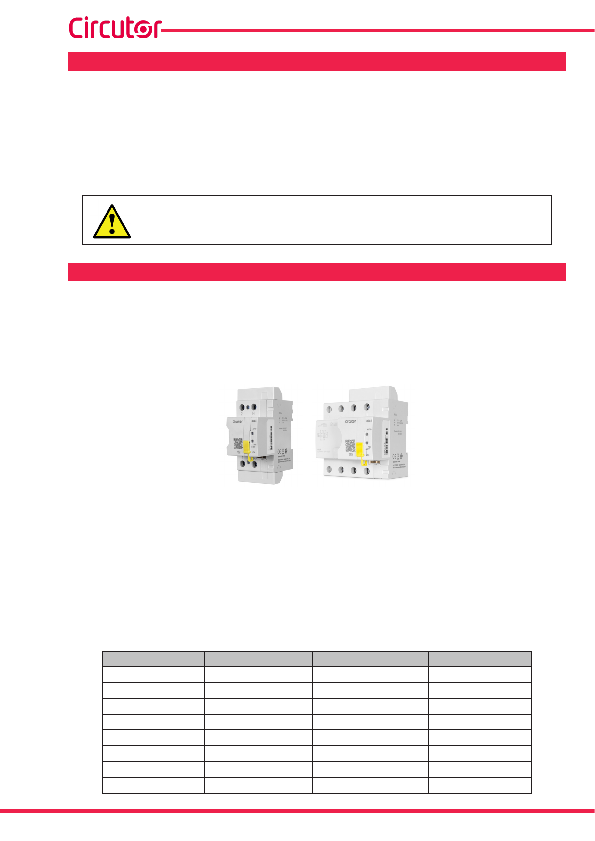
2. PRODUCT DESCRIPTION .................................................................................................................................................6
3. DEVICE INSTALLATION....................................................................................................................................................8
3.1.- PRIOR RECOMMENDATIONS ....................................................................................................................................8
3.2.- INSTALLATION .........................................................................................................................................................8
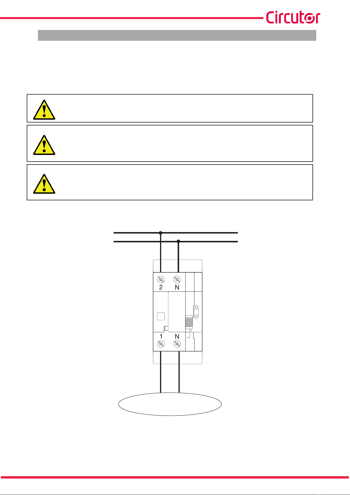
3.3.- CONNECTION ...........................................................................................................................................................9
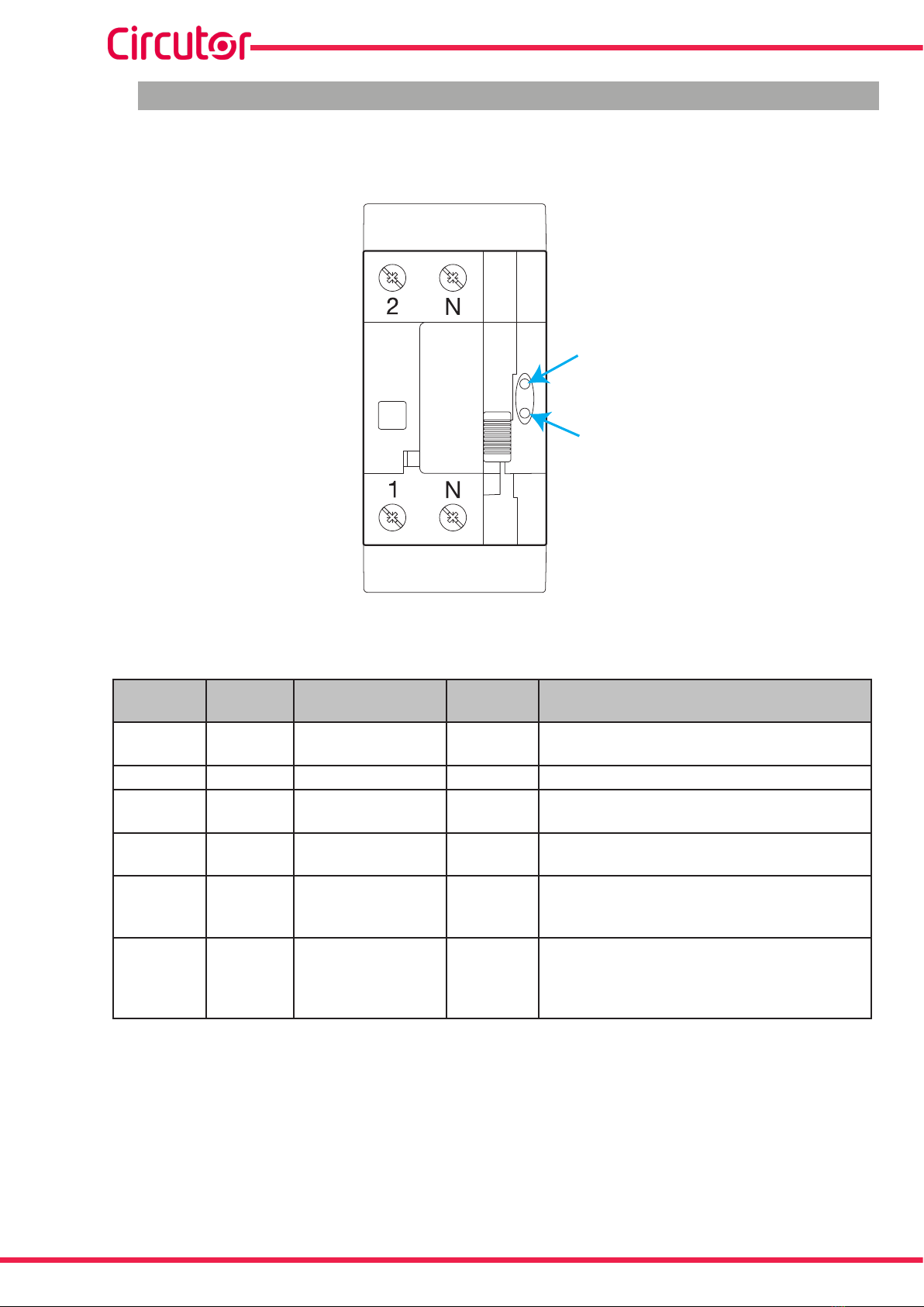
3.3.1.- CONNECTION DIAGRAM 2-POLE MODEL: REC4-2P, REC4-C-2P.......................................................................9
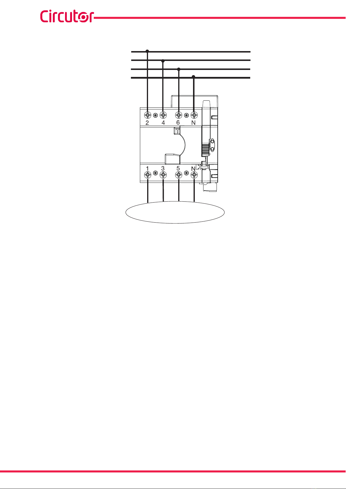
3.3.2.- CONNECTION DIAGRAM 4-POLE MODEL: REC4-4P, REC4-C-4P ..................................................................10
4. OPERATION ....................................................................................................................................................................11
4.1.- DESCRIPTION ..........................................................................................................................................................11
4.2.- LEDs ...................................................................................................................................................................... 12
4.3.-INDICATION OUTPUT (Model REC4-C) ................................................................................................................... 13
4.4.- START-UP .............................................................................................................................................................. 13
4.4.1.- AUTOMATIC MODE........................................................................................................................................... 13
4.4.2.- MANUAL MODE ............................................................................................................................................... 14
4.5.- OPERATING MODES ................................................................................................................................................ 14
4.5.1.- MANUAL .......................................................................................................................................................... 14
4.5.2.- AUTOMATIC ..................................................................................................................................................... 15
5. MAINTENANCE .............................................................................................................................................................. 17
6. TECHNICAL FEATURES..................................................................................................................................................18
7. TECHNICAL SERVICE......................................................................................................................................................23
8. GUARANTEE..................................................................................................................................................................23
9. EU DECLARATION OF CONFORMITY .............................................................................................................................24
4
REC4
Instruction Manual

PENDIENTE DE VALIDACIÓN
REVISION LOG
Table 1: Revision log.
Date Revision Description
11/18 M202B01-03-18A Initial Version
04/19 M202B01-03-20A Changes in the following sections:
2.- 3.3.- 4.1.- 4.2.- 6.
06/21 M202B01-03-21A Changes in the following sections:
4.2.
01/23 M202B01-03-23A Changes in the following sections:
2.- 3.3.- 4.1.- 4.3.- 4.4.1.- 4.4.2.- 4.5.1.- 4.5.2. - 5.- 6.
Note: The images of the devices are solely for the purpose of illustration and may differ from the orig-
inal device.
SYMBOLS
Table 2: Symbols
Symbol Description
In compliance with the relevant European directive.
Device covered by European directive 2012/19/EC. At the end of its useful life, do not leave the
unit in a household waste container. Follow local regulations on electronic equipment recycling.
DC current
~AC current
5
Instruction Manual
REC4

1. VERIFICATION UPON RECEPTION
Check the following points when you receive the device:
a) The device meets the specifications described in your order.
b) The device has not suffered any damage during transport.
c) Perform an external visual inspection of the device prior to switching it on.
d) Check that it has been delivered with the following:
- Installation guide
If any problem is noticed upon reception, immediately contact the transport com-
pany and/or CIRCUTOR’s after-sales service.
2. PRODUCT DESCRIPTION
REC4 is a 2 or 4-pole type A RCCB linked to a smart reclosing motor, which enables safe reclosing of
the corresponding RCCB.
In the REC4-2P model, the insulation reclosing mode is used for high sensitivity protection, so that
the device only recloses when the fault that caused tripping has disappeared. The rest of the models
implement the timed reclosing mode to ensure power supply continuity.
The device features:
- 2 LED indication.
- Automatic reclosing by insulation or Time, depending on the model (Table 3 and Tabla 4).
- Protection cover for the reclosing system.
- Mode selection switch to select between Manual and Automatic operating mode and physi-
cally lock the reclosing device.
- 1 indication output, to indicate the blocking of the device due to the maximum number of
reconnections (Model REC4-C).
Table 3: REC4 Models.
Models Reclosure mode Rated current (In) Sensitivity (In)
REC4-2P-40-30 Isolation 40 A 30 mA
REC4-2P-63-30 Isolation 63 A 30 mA
REC4-2P-40-300 Time 40 A 300 mA
REC4-2P-63-300 Time 63 A 300 mA
REC4-4P-40-30 Time 40 A 30 mA
REC4-4P-63-30 Time 63 A 30 mA
REC4-4P-40-300 Time 40 A 300 mA
REC4-4P-63-300 Time 63 A 300 mA
6
REC4
Instruction Manual

PENDIENTE DE VALIDACIÓN
Table 4: REC4-C Models.
Models Reclosure mode Rated current (In) Sensitivity (In)
REC4-C-2P-40-30 Time 40 A 30 mA
REC4-C-2P-63-30 Time 63 A 30 mA
REC4-C-2P-40-300 Time 40 A 300 mA
REC4-C-2P-63-300 Time 63 A 300 mA
REC4-C-4P-40-30 Time 40 A 30 mA
REC4-C-4P-63-30 Time 63 A 30 mA
REC4-C-4P-40-300 Time 40 A 300 mA
REC4-C-4P-63-300 Time 63 A 300 mA
7
Instruction Manual
REC4

3. DEVICE INSTALLATION
3.1.- PRIOR RECOMMENDATIONS
In order to use the unit safely, it is critical that those who handle it follow the safety
measures set out in the standards of the country where it is being used, use the neces-
sary personal protective equipment and pay attention to the various warnings indicated
in this instruction manual.
The REC4 device must be installed by authorised and qualified staff.
Also, it is critical to keep the cables in perfect condition in order to avoid accidents, personal injury and
damage to installations.
The manufacturer of the device is not responsible for any damages resulting from failure by the user
or installer to heed the warnings and/or recommendations set out in this manual, nor for damages
resulting from the use of non-original products or accessories or those made by other manufacturers.
If you detect any operational faults in the device or in its protection system, remove the device from
service.
This device has been designed for easy replacement in case of malfunction.
Disable the automatic reclosing function and disconnect the main protection device
before handling active parts.
Please contact the after-sales service if you suspect that there is an operational fault
in the device.
3.2.- INSTALLATION
Do not use the device until it is fully installed.
The REC4 is a device specifically designed to be installed in electric panels or enclosures, with DIN rail
fixing elements (IEC 60715).
To install the device on a DIN rail:
1.- Place the device at the top of the DIN rail.
2.- Swing the REC4 downwards until it is secured to the lower section of the DIN rail.
3.- Make sure that it has been secured on the rail.
8
REC4
Instruction Manual

PENDIENTE DE VALIDACIÓN
3.3.- CONNECTION
The REC4 must be connected to an installation protected with fuses suitable for its power supply range
and consumption.
Note: Cross-section of the cable: 16 - 25mm2
Terminals, opening covers or removing elements can expose parts that are hazardous
to the touch while the device is powered
If the REC4 indicates a permanent failure (AUTO and REC LEDs are lit), you must
check the RCCB and the installation.
If the installation of the device is done with the RCCB in the OFF state, when panel
receives voltage the device will not activate the automatic reclosing system for safety
reasons And the AUTO and REC LEDs turn on to turn off in a few seconds. A manual
reclosing of the system must be done on the panel with voltage.
3.3.1.- CONNECTION DIAGRAM 2-POLE MODEL: REC4-2P, REC4-C-2P
F
N
CARGA / LOAD
Figure 1: Connection diagram REC4-2P, REC4-C-2P.
9
Instruction Manual
REC4

3.3.2.- CONNECTION DIAGRAM 4-POLE MODEL: REC4-4P, REC4-C-4P
CARGA / LOAD
L3
N
L1
L2
Figure 2: Connection diagram REC4-C-4P: Three phase system.
10
REC4
Instruction Manual

PENDIENTE DE VALIDACIÓN
4. OPERATION
4.1.- DESCRIPTION
Figure 3 and Figure 4 shows a description of the most important pieces of device.
LEDs
Protection
cover
TEST key
Mode selection
switch
RCCB Control module
LEDs
Protection
cover
TEST key
Mode selection
switch
RCCB Control module
REC4-2P model REC4-2P model manufactured from 01/23.
REC4-C-2P model
Figure 3: Description of the REC4-2P and REC4-C-2P.
LEDs
Protection
cover
TEST key Mode selection
switch
RCCB Control module
RCCB Control module
Protection
cover
LEDs
TEST key
Mode selection
switch
REC4-4P model REC4-2P model manufactured from 01/23.
REC4-C-4P model
Figure 4: Description of the REC4-4P and REC4-C-4P.
(1)
11
Instruction Manual
REC4

4.2.- LEDs
The device has two LEDs: AUTO in green and REC in red, which indicate the status of the REC4 at all
times. (Figure 5 and Table 5)
AUTO
REC
AUTO
REC
Figure 5: LEDs REC4.
Table 5: LED indications.
AUTO REC Operating mode RCCB
status Description
OFF OFF Manual - Device is manual operating mode. There is no
power to the REC4.
ON OFF Automatic ON No rearm sequence has been initiated.
ON Slow
flashing Automatic OFF Rearm sequence initiated:
Time delay of the rearm sequence (if applicable).
ON Fast
flashing Automatic OFF Rearm sequence initiated:
Monitoring the leakage current.
ON ON Automatic OFF
The maximum number of reclosures has been
reached. The installation is in permanent failure
mode
Fast
flashing
Fast
flashing Alarm -
Make sure that the neutral connection has been
made correctly on the indicated terminal. If the de-
vice does not reset itself to the correct operating
mode, contact the TAS.
12
REC4
Instruction Manual

PENDIENTE DE VALIDACIÓN
4.3.-INDICATION OUTPUT (Model REC4-C)
The REC4-C model has an output that indicates the blocking of the device when the maximum number
of reconnections is exceeded (Figure 6 and Table 6).
7
8
Vmax: 300 Vac/dc
Imax: 0.1 A
Figure 6: Indication output (REC4-C).
Table 6: REC4-C terminals.
Terminals
7Indication output
8Indication output
4.4.- START-UP
Once the device is installed you must carry out the following start-up sequence for it to work properly.
4.4.1.- AUTOMATIC MODE
If the device is going to operate in automatic mode, see Section “4.5.2.- AUTOMATIC”, the start-up se-
quence is:
1.- Put the mode selector switch in Manual Mode (OFF).
2.- Lift the RCCB cover.
3.- Put the RCCB contact in ON mode.
4.- Lower the RCCB cover.
5.- Put the mode selector switch in Automatic Mode (ON).
Note: The switch has an M2 hole where you can attach a seal or a padlock to block access to the RCCB
and any other attempts at manual reclosing (Figure 7).
13
Instruction Manual
REC4

REC4-2P model REC4-2P model manufactured from 01/23.
REC4-C-2P model
Figure 7: Switch’s M2 hole to seal access to the RCCB.
4.4.2.- MANUAL MODE
If the device is going to operate in manual mode, see Section “4.5.1.- MANUAL”, the start-up sequence
is:
1.- Put the mode selector switch in Manual Mode (OFF).
2.- Lift the RCCB cover.
3.- Put the RCCB contact in ON mode.
4.- Lower the RCCB cover (optional).
4.5.- OPERATING MODES
The device has two operating modes, manual and automatic, which can be selected using the mode
selector switch (Figure 3 and Figure 4).
4.5.1.- MANUAL
The REC4 can operate in manual mode as if it were a standard RCCB.
To operate in this mode, the mode selector switch must be all the way to the top, in OFF position, to
disable the unit’s automatic reclosing device. (Figure 8)
The RCCB must be reclosed manually.
The AUTO and REC LEDs are off.
14
REC4
Instruction Manual

PENDIENTE DE VALIDACIÓN
REC4-2P model REC4-2P model manufactured from 01/23.
REC4-C-2P model
Figure 8: REC4 in manual mode, with mode selector switch at OFF.
4.5.2.- AUTOMATIC
To operate in Automatic mode the mode selector switch must be completely downward,in ON position,
to enable the device’s automatic reclosing system.(Figure 9)
The AUTO LED is constantly lit and the REC LED lights up based on the unit’s status.
REC4-2P model REC4-2P model manufactured from 01/23.
REC4-C-2P model
Figure 9: REC4 in automatic mode, with mode selector switch at ON.
The REC4 allows one mode of automatic reclosing:
- Reclosing by insulation, the device does not reclose until the leakage has disappeared.
4.5.2.1.- Reclosing by insulation
Following a time delay after a disconnection due to an RCCB trip, the REC4 makes a measurement to
check whether there is a leakage current. If there is none it begins to reclose.
The REC4 attempts a maximum of 3 measurements to check the leakage current; following this the
unit stays locked and does not automatically reclose.
15
Instruction Manual
REC4

If the time between a reclosure and the next trip is greater than the restart time, the reclosing attempts
start over at zero.
The delay and restart times depend on the number of attempts the reclosing device has made, as
shown in Table 7.
Table 7: Delay and Restart Times.
Reclosures
1 2 3
Delay Restart Delay Restart Delay Restart
<3 sec. 10 sec. 20 sec. 20 sec. 180 sec. 60 sec.
The leakage current will be supervised by measuring the resistance downstream of the tripped RCCB.
4.5.2.2.- Restarting the reclosing system meter
There are two ways to restart the internal reclosing system meter:
- Manually, by moving the mode selector switch from ON to OFF position and back to ON.
- Automatically, when the restart time elapses after the last reclosing without tripping again.
4.5.2.3.- Restart in case of blocking
In case of blocking of the device, the start-up sequence is:
1.- Check installation.
2.- Put the mode selector switch in Manual Mode (OFF).
3.- Lift the RCCB cover.
4.- Put the RCCB contact in ON mode.
5.- Lower the RCCB cover.
6.- Put the mode selector switch in Manual mode (ON).
Note: The switch has an M2 hole where you can attach a seal or a padlock to block access to the RCCB
and any other attempts at manual reclosing (Figure 7).
16
REC4
Instruction Manual

PENDIENTE DE VALIDACIÓN
5. MAINTENANCE
The RCCB must be checked frequently.
Test sequence (Figure 10):
1.- Press the TEST (T) key.
2.- Check that the RCCB jumps to OFF position.
TEST
OFF
TEST
OFF
REC4-2P model REC4-2P model manufactured from 01/23.
REC4-C-2P model
Figure 10: RCCB Test Sequence.
In the event of a Test sequence failure, contact the after-sales service.
17
Instruction Manual
REC4

6. TECHNICAL FEATURES
Power supply
Mode self-powered
Rated voltage 230V ~ ± 20%
Frequency 50Hz - 60Hz , ±5%
Maximum power consumption 6 VA
Installation category CAT III 300V
RCCB
Rated voltage REC4-2P, REC4-C-2P 230 V ~
REC4-4P, REC4-C-4P 400 V ~
Rated current (In)
REC4-2P-40-30, REC4-C-2P-40-30 40 A
REC4-2P-63-30, REC4-C-2P-63-30 63 A
REC4-2P-40-300, REC4-C-2P-40-300 40 A
REC4-2P-63-300, REC4-C-2P-63-300 63 A
REC4-4P-40-30, REC4-C-4P-40-30 40 A
REC4-4P-63-30, REC4-C-4P-63-30 63 A
REC4-4P-40-300, REC4-C-4P-40-300 40 A
REC4-4P-63-300, REC4-C-4P-63-300 63 A
Sensitivity (IΔn)
REC4-2P-40-30, REC4-C-2P-40-30 30 mA
REC4-2P-63-30, REC4-C-2P-63-30
REC4-2P-40-300, REC4-C-2P-40-300 300 mA
REC4-2P-63-300, REC4-C-2P-63-300
REC4-4P-40-30, REC4-C-4P-40-30 30 mA
REC4-4P-63-30, REC4-C-4P-63-30
REC4-4P-40-300, REC4-C-4P-40-300 300 mA
REC4-4P-63-300, REC4-C-4P-63-300
Resistance to surges class A , AC: 250A 8/20μs
class S: 3000A 8/20μs
Resistance to short-circuits Inc : 10000A a 230/400V with gB 80A fuse
Class A (IEC 61008.1)
Number of poles REC4-2P, REC4-C-2P 2
REC4-4P, REC4-C-4P 4
Rated marking and brealing capacity Im : 500 A
Working frequency 50/60 HZ
Measurement circuit
Models REC4-2P-xx-30: The leakage current will be supervised by measuring the resistance downstream of the RCCB.
Sensitivity Rd and Rd0 RCCB response
30 mA Rd < 8 KΩ no reclose
Rd0 > 16 KΩ reclose
User interface
LEDs 2 LED : AUTO in green and REC in red
Output (REC4-C model)
Type AC12
Maximum voltage 300 V ~/ 300 V
18
REC4
Instruction Manual

PENDIENTE DE VALIDACIÓN
(Continuation) Output (REC4-C model)
Maximum current 100 mA
Environmental features
Operating temperature Earth leakage protection -25ºC ... +55ºC
Automatic reclosing -10ºC ... +55ºC
Storage temperature - 35ºC ... +65ºC
Relative humidity (non-condensing) 5 ... 95%
Maximum altitude 2000 m
Resistance to pollution Category 2
Protection degree IP IP 20
Protection degree IK IK 08
Pollution degree 2
Use Indoor
Mechanical features
Terminals
1... 6, N 1 ... 25 mm2≤ 3 Nm M5 (Pozidrive PZ2)
REC4-C models: 7, 8 2.5 mm2≤ 0.4 Nm, M2.5 Flat
Fixing DIN rail
Weight
REC4-2P 296 g.
REC4-4P 496 g.
REC4-C-2P 300 g.
REC4-C-4P 500 g.
Material V0 Polycarbonate plastic
Colour RAL 7035
Dimensions (mm) Figure 11, Figure 12, Figure 13, Figure 14, Figure 15 and Figure 16
Standard
Residual current operated circuit-breakers without integral overcurrent protection for
household and similar uses (RCCB’s) -- Part 1: General rules UNE-EN 61008-1
Requirements for automatic reclosing devices (ARDs) for circuit breakers-RCBOs-RC-
CBs for household and similar uses UNE-EN 63024
19
Instruction Manual
REC4

81 54,5
5
35,5
115,6
87,5
45
76
Figure 11: REC4-2P dimensions.
45
35.5
5
54.5
115.5
87.5
81
76
42
Figure 12:REC4-2P dimensions (REC4-2P model manufactured from 01/23).
20
REC4
Instruction Manual
Other manuals for REC 4
2
This manual suits for next models
17
Table of contents
Other Circutor Industrial Electrical manuals
Popular Industrial Electrical manuals by other brands

Peter electronic
Peter electronic VB 230-6LT Assembly and commissioning instructions

Schrack
Schrack MC4-XR Series installation instructions

Siemens
Siemens SIRIUS 3RV19 Series Original operating instructions

Murata
Murata GRM1555C1H100JA01 Series Reference sheet

Murata
Murata GRM32CR72A684KA01 Series Reference sheet

Murata
Murata GRM0335C1H1R8CA01 Series Reference sheet