Circutor OPTIM FRS P&P Series User manual

INSTRUCTION MANUAL
(M090B01-03-19A)
Low voltage capacitor banks with detuned
lters, switched by contactors.
OPTIM FRS/FR P&P series

2
OPTIM FRS/FR P&P series
Instruction Manual

SAFETY PRECAUTIONS
DISCLAIMER
CIRCUTOR, SA reserves the right to make modi cations to the device or the unit speci ca-
tions set out in this instruction manual without prior notice.
CIRCUTOR, SA on its web site, supplies its customers with the latest versions of the device
speci cations and the most updated manuals.
www.circutor.com
CIRCUTOR, recommends using the original cables and accessories that are
supplied with the device.
DANGER
Warns of a risk, which could result in personal injury or material damage.
ATTENTION
Indicates that special attention should be paid to a speci c point.
Follow the warnings described in this manual with the symbols shown below.
If you must handle the unit for its installation, start-up or maintenance, the following
should be taken into consideration:
Incorrect handling or installation of the unit may result in injury to personnel as well as damage
to the unit. In particular, handling with voltages applied may result in electric shock, which may
cause death or serious injury to personnel. Defective installation or maintenance may also
lead to the risk of re.
Read the manual carefully prior to connecting the unit. Follow all installation and maintenance
instructions throughout the unit’s working life. Pay special attention to the installation stan-
dards of the National Electrical Code.
Refer to the instruction manual before using the unit
In this manual, if the instructions marked with this symbol are not respected or carried out correctly, it can
result in injury or damage to the unit and /or installations.
CIRCUTOR, SA reserves the right to modify features or the product manual without prior noti cation.
3
Instruction Manual
OPTIM FRS/FR P&P series

CONTENTS
SAFETY PRECAUTIONS .......................................................................................................................................3
DISCLAIMER ..........................................................................................................................................................3
CONTENTS .............................................................................................................................................................4
REVISION LOG .......................................................................................................................................................5
1.- VERIFICATION UPON RECEPTION ................................................................................................................. 6
1.1.- RECEPTION PROTOCOL .........................................................................................................................6
1.2.- TRANSPORT AND HANDLING ................................................................................................................6
1.3.- STORAGE .................................................................................................................................................7
2.- PRODUCT DESCRIPTION ................................................................................................................................ 8
3.- INSTALLATION .................................................................................................................................................8
3.1.- PRELIMINARY RECOMMENDATIONS .................................................................................................... 8
3.2.- PREPARATION ..........................................................................................................................................9
3.3.- PLACE OF INSTALLATION ....................................................................................................................10
3.4.-CONNECTION OF THE CAPACITOR BANK TO THE MAINS ................................................................ 11
3.5.-POWER CIRCUIT ..................................................................................................................................... 12
3.6.- EXTERNAL CIRCUIT BREAKER AND PROTECTION ELEMENTS ...................................................... 12
3.7.- AUXILIARY CONTROL VOLTAGE ..........................................................................................................13
3.8.- EARTH CABLE CONNECTION .............................................................................................................. 13
3.9.- CURRENT TRANSFORMER (CT) CONNECTION ................................................................................13
4.- CAPACITOR BANK START-UP .....................................................................................................................15
4.1.- BEFORE START-UP ................................................................................................................................15
4.2.- START-UP ................................................................................................................................................15
4.3.- CHECKS ONCE THE CAPACITOR BANK HAS BEEN CONNECTED AND THE REGULATOR HAS
BEEN ADJUSTED ...........................................................................................................................................16
5.- MAINTENANCE ...............................................................................................................................................18
5.1.- SAFETY REGULATIONS ........................................................................................................................ 18
5.2.- MAINTENANCE WITH THE CAPACITOR BANK DISCONNECTED ..................................................... 18
5.2.1. BASIC MAINTENANCE PROTOCOL ..............................................................................................18
5.2.2. KEY POINTS FOR INSPECTING CONTACTORS ........................................................................... 19
5.2.3. KEY POINTS FOR INSPECTING CAPACITORS.............................................................................19
5.2.4. KEY POINTS FOR INSPECTING THE REGULATOR ..................................................................... 20
5.2.5. CLEANING THE CABINET .............................................................................................................. 20
5.3.- MAINTENANCE WITH THE CAPACITOR BANK CONNECTED ........................................................... 20
5.3.1. REGULATOR CHECKS ....................................................................................................................21
5.4.- ENVIRONMENTAL CONDITIONS ........................................................................................................... 21
6.- TECHNICAL FEATURES ................................................................................................................................22
7.- STANDARD ELECTRICAL DIAGRAMS .........................................................................................................23
8.- MAINTENANCE AND TECHNICAL SERVICE ................................................................................................ 28
9.- GUARANTEE ...................................................................................................................................................28
10.- CE CERTIFICATE ..........................................................................................................................................29
4
OPTIM FRS/FR P&P series
Instruction Manual

REVISION LOG
Table 1: Revision log.
Date Revision Description
10/15 M090B01-03-15A Initial Version
03/16 M090B01-03-16A Changes in the following sections:
3.9.
04/16 M090B01-03-16B Changes in the following sections:
3.9.
11/19 M090B01-03-19A Changes in the following sections:
3.2. - 4.2. - 10.
Note: The images of the devices are for illustrative purposes only and may differ from the
original device.
5
Instruction Manual
OPTIM FRS/FR P&P series

1.- VERIFICATION UPON RECEPTION
1.1.- RECEPTION PROTOCOL
Check the following points when you receive the device:
a) The device meets the specications described in your order.
b) The device has not suffered any damage during transport.
c) Perform an external visual inspection of the device prior to switching it on.
d) Check that it has been delivered with the following:
- The device manual
- The installed regulator manual.
If any problem is noticed upon reception, immediately contact the transport
company and/or CIRCUTOR's after-sales service.
1.2.- TRANSPORT AND HANDLING
The transport, loading and unloading and handling of the device must be car-
ried out with proper precautions and using the proper manual and mechanical
tools so as not to damage it.
If the device is not to be immediately installed, it must be stored at a location
with a rm and level oor, and the storage conditions listed in the technical
features section must be observed. In this case, it is recommended that the
device be stored with its original protective packaging.
To move the device a short distance, the device's oor support proles facilitate handling with a
pallet jack or forklift. (Figure 1)
Figure 1: Transport with pallet jack.
The centre of gravity of some devices may be found at a considerable height.
Therefore, when handling with a forklift, it is recommended that the device be
securely fastened and that no abrupt manoeuvres made. The device should
not be lifted more than 20 cm off the ground
6
OPTIM FRS/FR P&P series
Instruction Manual

When unloading and moving the device, use a forklift with forks long enough to support the
entire length of the base. Otherwise, the forks should be long enough to support at least ¾
of said depth. The forks must be at and supported rmly by the base. Raise the cabinet by
placing the forks underneath the prole that supports the device. (Figure 2).
There might be an offset in the centre of gravity from the centre of the cabinet,
as a result of the uneven distribution of loads inside the device. The neces-
sary precautions must be taken to prevent the device from tipping over during
abrupt operations.
Figure 2: Unloading with a forklift.
1.3.- STORAGE
The following storage recommendations must be followed for the hybrid capacitor banks:
Avoid placing them on uneven surfaces.
Do not store them in outdoor areas, humid areas or areas exposed to splashing wa-
ter.
Avoid hot spots (maximum ambient temperature: 40 ºC)
Avoid salty and corrosive environments.
Avoid storing the devices in areas where a lot of dust is generated or where the
risk of chemical or other types of contamination is present.
Do not place any weight on top of the device cabinets.
7
Instruction Manual
OPTIM FRS/FR P&P series
2.- PRODUCT DESCRIPTION
The purpose of this manual is to assist during the installation, start-up and maintenance of
OPTIM FRS/FR P&P series low voltage (LV) capacitor banks with detuned lters, switched by
contactors. Carefully read the manual to get the best performance from these devices.
3.- INSTALLATION
3.1.- PRELIMINARY RECOMMENDATIONS
In order to use the device safely, it is critical that individuals who handle it follow
the safety measures set out in the standards of the country where it is being used,
use the personal protective equipment necessary, and pay attention to the vari-
ous warnings indicated in this instruction manual.
Installation or maintenance personnel should read and understand this manual
before operating the device.
A copy of this manual should always be available to maintenance personnel for
reference purposes
Connecting the device to the public mains must be carried out in compliance with
the EN-IEC60204-1 standard, regarding the safety of LV electrical installations.
It is recommended that several personnel are present when handling the device
for installation or maintenance.
If damage or faults are detected during device operation, or in circumstances that
compromise safety, immediately stop work in that area and disconnect the device
in order to check it without voltage.
The manufacturer of the device is not responsible for any damage resulting from failure by the
user or installer to heed the warnings and/or recommendations set out in this manual, nor for
damage resulting from the use of products or accessories that did not come with the device or
that were made by other manufacturers.
If an anomaly or malfunction is detected in the device, do not use it to perform any operation.
Modifying, upgrading or rebuilding the device without written authorisation from
the manufacturer is prohibited.
The installation, operation and maintenance of low voltage (LV) devices must
only be carried out by authorised installers. LV regulations (Art. 22) specically
dene the requirements that authorised installers must meet.
Do not access the active elements of a capacitor bank with static operation that
has been powered and might have voltages present. Wait at least 5 minutes af-
ter the power supply has been disconnected.
8
OPTIM FRS/FR P&P series
Instruction Manual
Do not touch the terminals or active parts of the device until you have veried that
voltage is not present. If you have to handle or touch the terminals or other control
panel components, use adequately insulated personal protection equipment and
tools.
After any maintenance and before re-connecting the power supply to the device,
check that its enclosure is properly closed and that no items or tools were left
inside that could cause a short-circuit.
Do not disconnect the current transformer secondary without short-circuiting it
rst. The operation of a current transformer with an open secondary will cause an
overvoltage that could damage it and electrocute the person handling it.
3.2.- PREPARATION
The CIRCUTOR OPTIM FRS/FR P&P static capacitor banks come ready for easy installation
and start-up.
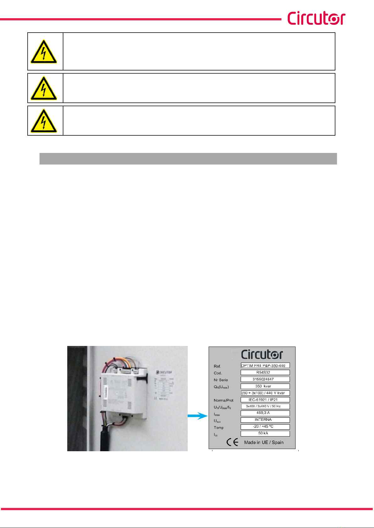
Remove the packaging of the device and verify that its electrical features are suitable for con-
nection to the available mains. To do so, check the features label located inside the cabinet next
to the regulator, see Figure 3.
Key data to be checked:
Mains frequency and voltage, Un / fn.
Nominal power of the capacitor bank, Qn (kvar) and composition.
Type of lter, identied by the factor p%.
Current consumption, In . This current must be considered to select the proper size
of the power supply cable of the device and ultimately the circuit breakers and protection
elements to be connected in front of it.
Auxiliary control voltage, Uaux.( See "3.7.- AUXILIARY CONTROL VOLTAGE”)
Environmental conditions. (See “6.- TECHNICAL FEATURES”)
Figure 3: Features label.
9
Instruction Manual
OPTIM FRS/FR P&P series

3.3.- PLACE OF INSTALLATION
It is important to maintain a minimum distance around the device to facilitate cooling.
In self-supporting cabinets, the back and front sides of the cabinet must be kept at least 50 cm
away from walls of other devices and structures to allow for ventilation.
In terms of the side walls, it is recommended that a separation of 10 cm be maintained between
adjacent cabinets.
On wall-mounted cabinets, it is recommended that at least 20 cm of separation be maintained
between the sides of adjacent cabinets.
Make sure the device can be accessed easily.
The environmental conditions of the place where the device is installed must not exceed the
limits set forth in the technical features (See "6.- TECHNICAL FEATURES”)
To ensure proper ventilation, the device must be installed in a vertical position.
In accordance with the LVR, once the device is installed it must be protected against direct
and indirect contacts; therefore, a circuit breaker and earth leakage protection for the capacitor
bank's power supply line should be installed.
10
OPTIM FRS/FR P&P series
Instruction Manual
3.4.-CONNECTION OF THE CAPACITOR BANK TO THE MAINS
Check that the rated voltage of the capacitor bank matches the voltage between
phases of the grid to which it is being connected.
Also check the operating circuit voltage (contactors). (See “3.7.- AUXILIARY CON-
TROL VOLTAGE”)
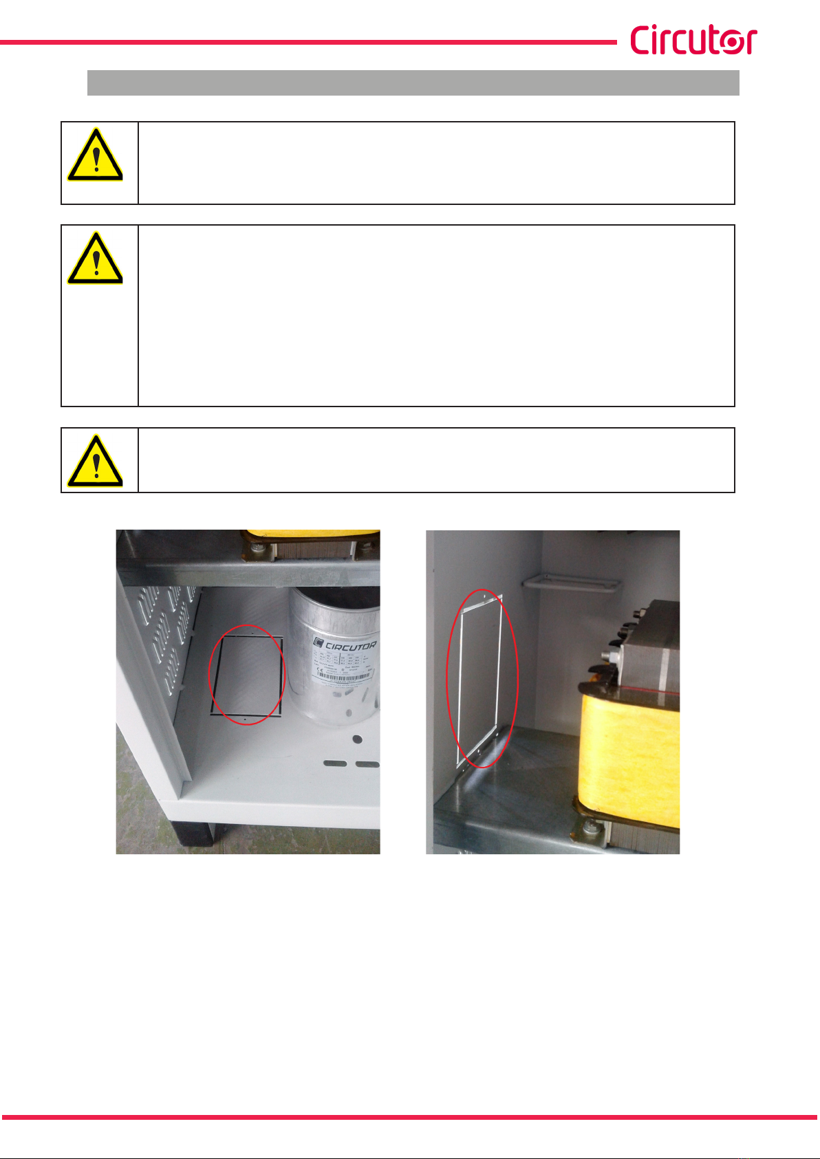
For feeding cables into the capacitor bank cabinet, always and only use the cable
entry points available for this purpose.
All models have a cable entry point on the bottom (base of the cabinet) as well as
a cable entry point on the side.
Figure 4 shows the cable entry points of the OPTIM FRS P&P models.
Figure 5 shows the cable entry points of the OPTIM FR P&P models.
If another part of the cabinet is cut out to be used for cable entry, the CIR-
CUTOR manufacturer's guarantee shall be rendered void.
Do not cut holes in other parts of the cabinet for feeding cables through or for
installing support brackets.
It may produce trimmings that can cause short-circuits.
Figure 4: Cable entry points of the OPTIM FRS P&P models.
11
Instruction Manual
OPTIM FRS/FR P&P series

Figure 5: Cable entry points of the OPTIM FR P&P models.
3.5.-POWER CIRCUIT
Connect input terminals L1, L2 and L3 (power circuit) to the mains using a cable with a suitable
cross-section, in accordance with the LVR, ITC-BT-19.
Generally, the phase cables are according to the following colour code: L1 (black), L2 (brown),
L3 (grey).
In order to determine the size of the phase cables, consider the nominal current In indicated on
the device label, and it should be able to withstand transient overloads of 1.5 times In.
3.6.- EXTERNAL CIRCUIT BREAKER AND PROTECTION ELEMENTS
If the capacitor bank does not have an internal switch or isolation switch, it must be connected
to a line that has an external switch or isolation switch.
The protection elements, isolation switches and/or switches that are added exter-
nally to the capacitor bank must be of a minimum size to withstand a current 1.5
times greater than what is indicated on the label (LVR, ICT-BT-48)
If an earth leakage protection for the capacitor bank is installed, its sensitivity and
trip delay must be adjustable.
When the capacitor bank is connected to the mains, it is recommended that the current
transformer (CT) is placed on the phase going to L1 (black cable).
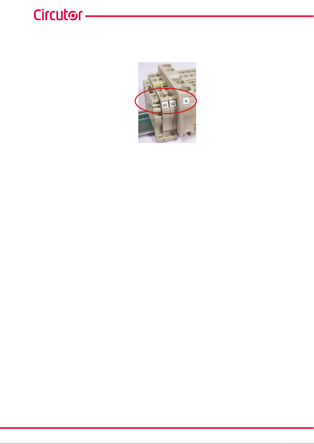
Outputs S1 and S2 of the CT must be connected to the terminals with the same name.
12
OPTIM FRS/FR P&P series
Instruction Manual
3.7.- AUXILIARY CONTROL VOLTAGE
Control circuits are dened as those related with regulator output relays and the capacitor's
operating contactors. These circuits are usually powered with a 230 V~ auxiliary voltage (most
common).
For all the standard models of the OPTIM FRS P&P and OPTIM FR P&P range, the auxiliary
voltage is supplied from an internal AUTOTRANSFORMER: Does not require connection
of the external neutral. The label indicates Uaux/f … internal
3.8.- EARTH CABLE CONNECTION
Connect the earth cable to the capacitor bank's earth terminal located on the operating panel
of the device.
The cross-section of the earth cable must be selected in accordance with the admissible cur-
rent limits established in the LVR (ITC-BT-19 – Internal or receiver installations) for each type
of cable and location.
3.9.- CURRENT TRANSFORMER (CT) CONNECTION
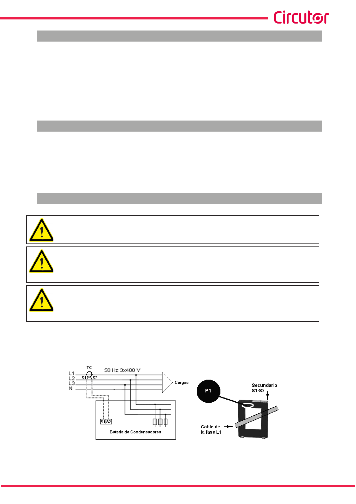
A current transformer (CT) that is external to the capacitor bank must be
installed to measure the total load current plus that of the capacitor bank
(Figure 6).
The standard transformer must have a nominal output of 5 A at the secondary.
We recommend connecting the CT to phase L1 in the direction of the current ow
from P1 to P2 (see Figure 6) and connecting the secondary (terminals S1, S2) to
the terminals with the same name on the capacitor bank (see Figure 6)
Avoid current ow through the CT primary winding prior to connecting it to termi-
nals S1 S2 of the bank.
If the CT must be installed while the installation is under load, short-circuit S1 and
S2 while they are not connected to the capacitor bank.
The current value of the CT primary winding must be equal to or slightly greater than the size of
the mains switch of the installation. Therefore, the CT must be able to measure the maximum
current expected to be consumed by all the loads being compensated.
Figure 6: Installation of the external current transformer (CT).
The connection point of the CT for a capacitor bank that compensates an entire installation is
13
Instruction Manual
OPTIM FRS/FR P&P series
after the mains switch of the installation.
To prevent excessive attenuation of the signal, it is recommended that the minimum cross-sec-
tion of the secondary winding cable (terminals S1, S2) is at least 2.5 mm2.
Figure 7: Current transformer (CT) connection terminals.
14
OPTIM FRS/FR P&P series
Instruction Manual

4.- CAPACITOR BANK START-UP
4.1.- BEFORE START-UP
The automatic capacitor banks include a power factor regulator.
The operation of said regulator must be known prior to start-up; for this reason,
all the capacitor banks include a specic manual for the regulator used.
Ensure you have this manual available for the start-up process.
In order to adjust the regulator incorporated to the capacitor bank and for opti-
mum start-up, the installation load must be at least 30% or 40% of the nominal
load for which the capacitor bank has been dimensioned. If all the stages are not
included, they can be manually connected to check them all.
During low load periods, the entire capacitor bank should not be connected man-
ually, as in some cases resonance with the power transformer of the installation
could occur.
The capacitors are connected in manual mode, rst allow enough time for the ca-
pacitors to discharge (as indicated in the capacitor bank's features label) before
reconnecting them to the network.
Otherwise, they could start-up out of phase with a voltage of up to 2xUn causing
the destruction of the capacitor.
4.2.- START-UP
Before operating the devices, follow the safety regulations indicated in section
“3.- INSTALLATION” of this manual.
The National Electric Code of the country where the capacitor bank is in-
stalled or operated should be strictly followed.
1.- Make sure that the internal circuit breaker that protects the regulator (two-pole or three-pole
depending on the regulator) is connected (│ position).
2.- Connect the power supply to the panel and check that the regulator display is immediately
lit. Otherwise, stop and check the previous step.
3.- Check the regulator's cos φ indication.
If the indication is out of range 0.5 to 1, it may be possible that the current transformer and/or
the power supply to the regulator are not properly connected.
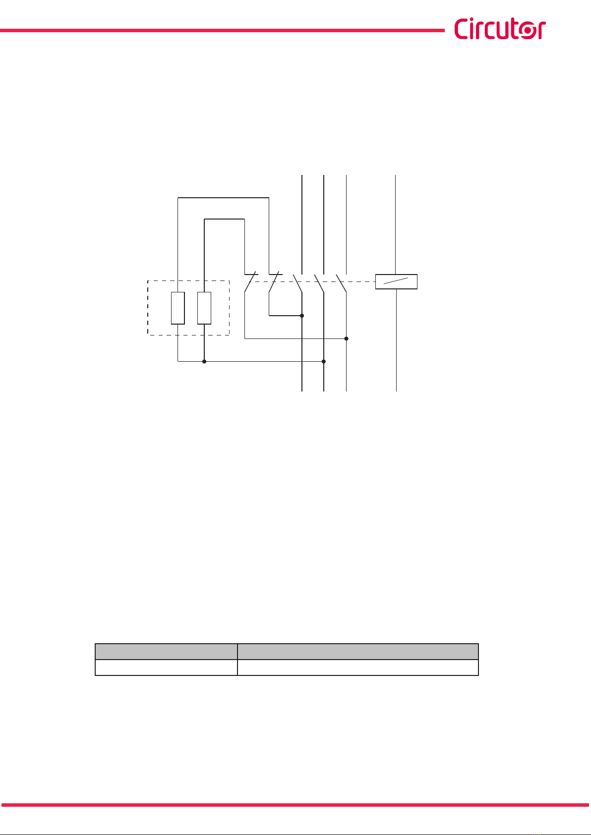
Most of the regulators only use a single current transformer. In this case, connect according to
Figure 9 (place the current transformer on phase L1 and take the power supply voltage from
phases L2 and L3).
15
Instruction Manual
OPTIM FRS/FR P&P series

Figure 8: Plug&Play Computer Max Regulator. (Photo as an example, it may not coincide with the model used on
your device).
- + C1 ... C6
-
L1
L2
L3
N
POWER
SUPPLY
0
1 2 3456
400 V ac
A B
P1 P2
S1 S2
C D
Figure 9: Connection of a regulator with only one CT. (If using Computer SMART III or Computer Plus, 3 CT are used.
Check the specic manual. )
4.- Once making sure that the regulator is properly connected, adjust the regulator parameters
for the installation you are attempting to compensate. For this, follow the instructions described
in the regulator manual included with the capacitor bank.
4.3.- CHECKS ONCE THE CAPACITOR BANK HAS BEEN CONNECTED AND THE
REGULATOR
1.- After start-up, make sure that the device is operating correctly. A sign of proper operation is
when the display indicates a cos φ close to 1 and the reactive energy meter stops (if it is elec-
tromechanical) or the blinking rate of the kvar.h/pulse ratio indicator LED slows down.
2.- Check that the power supply voltage does not exceed the nominal value +10% (IEC 60831-
1).
3.- Check the current absorbed by each capacitor.
Under normal conditions, it must be close to the nominal value indicated on its dataplate and
never exceed 1.3 times this value constantly.
Continuous consumption over the nominal value may be caused by the presence of harmonics
in the network or an excessively high power supply voltage. Both circumstances are harmful
for capacitors.
4.- In accordance with the IEC 60831-1 Standard, the capacitor is prepared to operate at the
permanent voltage assigned to it and with an overvoltage of up to 10% for 8 out of every 24
hours.
16
OPTIM FRS/FR P&P series
Instruction Manual

NOTE: For capacitor banks with lters, the capacitor's voltage exceeds the network voltage by
a % that is approximately equal to the lter's overvoltage factor (p%). In fact, the capacitor's
real overvoltage is:
%)p100(
%p.100
%
V
V
RED
C
−
=
∆
5.- To check the lter's correct tuning, make sure that the voltage on the terminals of each wind-
ing of the reactor is:
%)100(
%.100
.p
p
VV
REDL
−
=
Check the working temperature of the capacitors and reactors after they have
been operating for 24 hours.
The capacitor capsule must be under 40ºC.
The housing of reactors can reach temperatures of about 70 ºC
17
Instruction Manual
OPTIM FRS/FR P&P series

5.- MAINTENANCE
5.1.- SAFETY REGULATIONS
Before operating the devices, follow the safety regulations indicated in section
“3.1.- PRELIMINARY RECOMMENDATIONS” of this manual
The National Electric Code of the country where the capacitor bank is installed or
operated should be strictly followed.
5.2.- MAINTENANCE WITH THE CAPACITOR BANK DISCONNECTED
5.2.1. BASIC MAINTENANCE PROTOCOL
Monthly:
Visually inspect the capacitors.
Check the protection fuse.
Control the ambient temperature (average of 35 ºC. In accordance with IEC 60831 ).
Control the service voltage (especially during moments of low load, when it must not
exceed the nominal +10%).
Biannually:
Keep the capacitor terminals clean.
Verify the condition of the contacts on the operation elements.
Check that the capacitor current is not lower than 25% nor greater than 120% of the
nominal value by phase and that there is no phase unbalance greater than 15%.
Annually:
Perform a dielectric rigidity test by applying 2.5 kV for 1 second between the terminals
of the capacitor and earth.
Check the capacity of the capacitors at the different steps.
One indirect check may be to check that the consumption is manual.
Check the tightness of all terminal connections.
Inspect the fuses and/or circuit breakers.
- Power Circuit: NH fuses. Check continuity and temperature.
- Power Circuit: Check the continuity and temperature of the three-pole circuit breaker.
- Control Circuit: Check the continuity and temperature of the two-pole or three-pole
circuit breaker, depending on the regulator.
18
OPTIM FRS/FR P&P series
Instruction Manual
5.2.2. KEY POINTS FOR INSPECTING CONTACTORS
Check that the plastic parts are not blackened and do not show signs of burning or hardening.
Check that the head is properly inserted.
The terminals must be clean.
If the capacitor bank includes RD discharge resistors, check that they are in good condition
(they are not open and show no signs of burning). (Figure 10)
RD K1
Figure 10: Connection of the discharge resistors.
Cleaning the contactors: In dirty environments (dust, sawdust, rust particles, etc.) vacuum
the contactor periodically.
There is no estimated time frame for cleaning, it depends on the amount of dirt that is inside the
capacitor bank.
5.2.3. KEY POINTS FOR INSPECTING CAPACITORS
Inspect the cables and terminals. They should not be overheated or blackened.
The terminals must be clean.
The slow discharge resistors must be in good condition. They must not be open or show
signs of burning.
Check the tightness of the capacitor terminals, as shown in Table 2.
Table 2:Torques of the cables to the capacitor terminals.
Cylindrical capacitor Power terminal torque (Nm)
CLZ-FP 2
19
Instruction Manual
OPTIM FRS/FR P&P series

5.2.4. KEY POINTS FOR INSPECTING THE REGULATOR
Check that the regulator does not show signs of deterioration and the display is lit as normal.
Inspect the cables and terminals. They should be clean and should not be hardened or over-
heated.
Inspect the connections and the insertion of removable power strips:
- The power strips must be well fastened on removable regulators.
- Check that the terminals are tightened properly. The recommended torque is 0.6 Nm.
5.2.5. CLEANING THE CABINET
Remove possible metallic and non-metallic particles.
Clean the inside of the cabinet.
Clean ventilation grilles.
5.3.- MAINTENANCE WITH THE CAPACITOR BANK CONNECTED
Check that the main switch turns on and off without having to force the mechanism.
If there is an individual earth leakage protection for the capacitor bank, check its proper func-
tioning by pressing the test button.
Check that the auxiliary control voltage is within the tolerance limits.
If the capacitor bank has an autotransformer, check that it is in good condition and shows no
signs of deterioration.
Force the connection and disconnection of the capacitors in manual mode. (refer to the reg-
ulator's manual before carrying out these actions) and perform the following checks:
- Check that the contactors connect and disconnect properly.
- Check that the contactor, once connected, does not rattle or vibrate.
- Check the consumption of the capacitors in each of the phases.
The nominal values are shown in Table 3.
.
Table 3:Nominal consumption of the capacitor paths, by power and voltage.
Power In, Current
3 x 230 V ~3 x 400V~
2.5 kvar 6.28 A 3.6 A
5 kvar 12.56 A 7.2 A
7.5 kvar 18.85 A 10.8 A
10 kvar 25.12 A 14.4 A
12.5 kvar 31.41 A 18 A
15 kvar 37.7 A 21.6 A
20 kvar 50.24 A 28.8 A
25 kvar 62.82 A 36 A
30 kvar 75.4 A 43.2 A
40 kvar 100.48 A 57.6 A
50 kvar - 72 A
60 kvar - 86.4 A
20
OPTIM FRS/FR P&P series
Instruction Manual
This manual suits for next models
7
Table of contents
Other Circutor Industrial Electrical manuals


Popular Industrial Electrical manuals by other brands


Murata
Murata GRM152C80J104KE19 Series Reference sheet

Murata
Murata GRM31MR72A563KA01 Series Reference sheet

Murata
Murata GRM0335C1ER30WA01 Series Reference sheet

Thermon
Thermon Terminator ZE-S installation instructions

Lumel
Lumel SR11 Series User Manual & Quick Start

Murata
Murata GRM21BC71H475KE11 Series Reference sheet


