Circutor OPTIM HYB Series User manual
INSTRUCTION MANUAL
(M059B01-03-19A)
Low voltage capacitor bank with static operation.
OPTIM HYB Series

2
OPTIM HYB Series
Instruction Manual

SAFETY PRECAUTIONS
DISCLAIMER
CIRCUTOR, SA reserves the right to make modi cations to the device or the unit speci ca-
tions set out in this instruction manual without prior notice.
CIRCUTOR, SA on its web site, supplies its customers with the latest versions of the device
speci cations and the most updated manuals.
www.circutor.com
CIRCUTOR, recommends using the original cables and accessories that are
supplied with the device.
DANGER
Warns of a risk, which could result in personal injury or material damage.
ATTENTION
Indicates that special attention should be paid to a speci c point.
Follow the warnings described in this manual with the symbols shown below.
If you must handle the unit for its installation, start-up or maintenance, the following
should be taken into consideration:
Incorrect handling or installation of the unit may result in injury to personnel as well as damage
to the unit. In particular, handling with voltages applied may result in electric shock, which may
cause death or serious injury to personnel. Defective installation or maintenance may also
lead to the risk of re.
Read the manual carefully prior to connecting the unit. Follow all installation and maintenance
instructions throughout the unit’s working life. Pay special attention to the installation stan-
dards of the National Electrical Code.
Refer to the instruction manual before using the unit
In this manual, if the instructions marked with this symbol are not respected or carried out correctly, it can
result in injury or damage to the unit and /or installations.
CIRCUTOR, SA reserves the right to modify features or the product manual without prior noti cation.
3
Instruction Manual
OPTIM HYB Series

CONTENTS
SAFETY PRECAUTIONS .......................................................................................................................................3
DISCLAIMER ..........................................................................................................................................................3
CONTENTS.............................................................................................................................................................4
REVISION LOG.......................................................................................................................................................5
1.- VERIFICATION UPON RECEPTION................................................................................................................. 6
1.1.- RECEPTION PROTOCOL..........................................................................................................................6
1.2.- TRANSPORT AND HANDLING .................................................................................................................6
1.3.- STORAGE...................................................................................................................................................7
2.- PRODUCT DESCRIPTION................................................................................................................................8
2.1.- CAPACITOR BANK COMPONENTS.........................................................................................................8
2.1.1. HYBRID REGULATOR ......................................................................................................................... 8
2.1.2. CPC2 PANEL: ZERO SWITCHING CONNECTION CONTROL BY TWO SINGLE-PHASE
STAGES........................................................................................................................................................ 13
2.1.3. SINGLE-PHASE POWER BLOCK ..................................................................................................... 14
2.1.4. THREE-PHASE POWER BLOCK ...................................................................................................... 14
2.1.5. MAINS CONNECTION TERMINALS.................................................................................................. 14
3.- INSTALLATION ...............................................................................................................................................15
3.1.- PRELIMINARY RECOMMENDATIONS ................................................................................................... 15
3.2.- PREPARATION.........................................................................................................................................16
3.3.- INSTALLATION LOCATION..................................................................................................................... 17
3.4.-CONNECTION OF THE CAPACITOR BANK TO THE MAINS................................................................. 17
3.5.-POWER CIRCUIT ...................................................................................................................................... 18
3.6.- EXTERNAL ISOLATION AND PROTECTION ELEMENTS..................................................................... 19
3.7.- AUXILIARY CONTROL VOLTAGE........................................................................................................... 19
3.8.- EARTH CABLE CONNECTION ...............................................................................................................19
3.9.- CURRENT TRANSFORMER (CT) CONNECTION ................................................................................. 20
4.- START-UP OF A HYBRID CAPACITOR BANK ..............................................................................................22
4.1.- BEFORE START-UP.................................................................................................................................22
4.2.- START-UP.................................................................................................................................................22
4.3.- CHECKS ONCE THE CAPACITOR BANK HAS BEEN CONNECTED TO THE MAINS........................ 26
5.- MAINTENANCE...............................................................................................................................................27
5.1.- SAFETY REGULATIONS .........................................................................................................................27
5.2.- MAINTENANCE WITH THE CAPACITOR BANK DISCONNECTED ...................................................... 27
5.2.1. BASIC MAINTENANCE PROTOCOL ................................................................................................ 27
5.2.2. TIGHTENING TORQUE OF THE ELECTRICAL CONNECTIONS .................................................... 28
5.2.3. KEY POINTS FOR INSPECTING CONTACTORS............................................................................. 28
5.2.4. KEY POINTS FOR INSPECTING STATIC SWITCHES...................................................................... 29
5.2.5. KEY POINTS FOR INSPECTING CAPACITORS...............................................................................29
5.2.6. KEY POINTS FOR INSPECTING THE REGULATOR .......................................................................29
5.2.7. CLEANING THE CABINET ................................................................................................................ 29
5.3.- MAINTENANCE WITH THE CAPACITOR BANK CONNECTED ............................................................30
5.4.- ENVIRONMENTAL CONDITIONS............................................................................................................30
6.- TECHNICAL FEATURES ................................................................................................................................31
7.- OPTIM HYP TYPE DIAGRAM.........................................................................................................................32
8.- MAINTENANCE AND TECHNICAL SERVICE................................................................................................ 34
9.- GUARANTEE...................................................................................................................................................34
10.- CE CERTIFICATE..........................................................................................................................................35
4
OPTIM HYB Series
Instruction Manual

REVISION LOG
Table 1: Revision log.
Date Revision Description
11/14 M059B01-03-14A Initial Version
02/15 M059B01-03-15A Changes in the following sections:
6
11/19 M059B01-03-19A Changes in the following sections:
2.1.1. - 2.1.1.1. - 2.1.1.2. - 3.2.
Note: The images of the units are solely for the purpose of illustration and may differ from the
original unit.
5
Instruction Manual
OPTIM HYB Series
1.- VERIFICATION UPON RECEPTION
1.1.- RECEPTION PROTOCOL
Check the following points when you receive the unit:
a) The unit meets the specications described in your order.
b) The unit has not suffered any damage during transport.
c) Perform an external visual inspection of the unit prior to switching it on.
d) Check that it has been delivered with the following:
- The unit manual.
- The CVM-MINI-RS485 quick installation guide.
If any problem is noticed upon reception, immediately contact the transport
company and/or CIRCUTOR's after-sales service.
1.2.- TRANSPORT AND HANDLING
The transport, loading and unloading and handling of the unit must be carried
out with proper precautions and using the proper manual and mechanical
tools so as not to damage it.
If the unit is not to be immediately installed, it must be stored at a location
with a rm and level oor, and the storage conditions listed in the technical
features section must be observed. In this case, it is recommended that the
unit be stored with its original protective packaging.
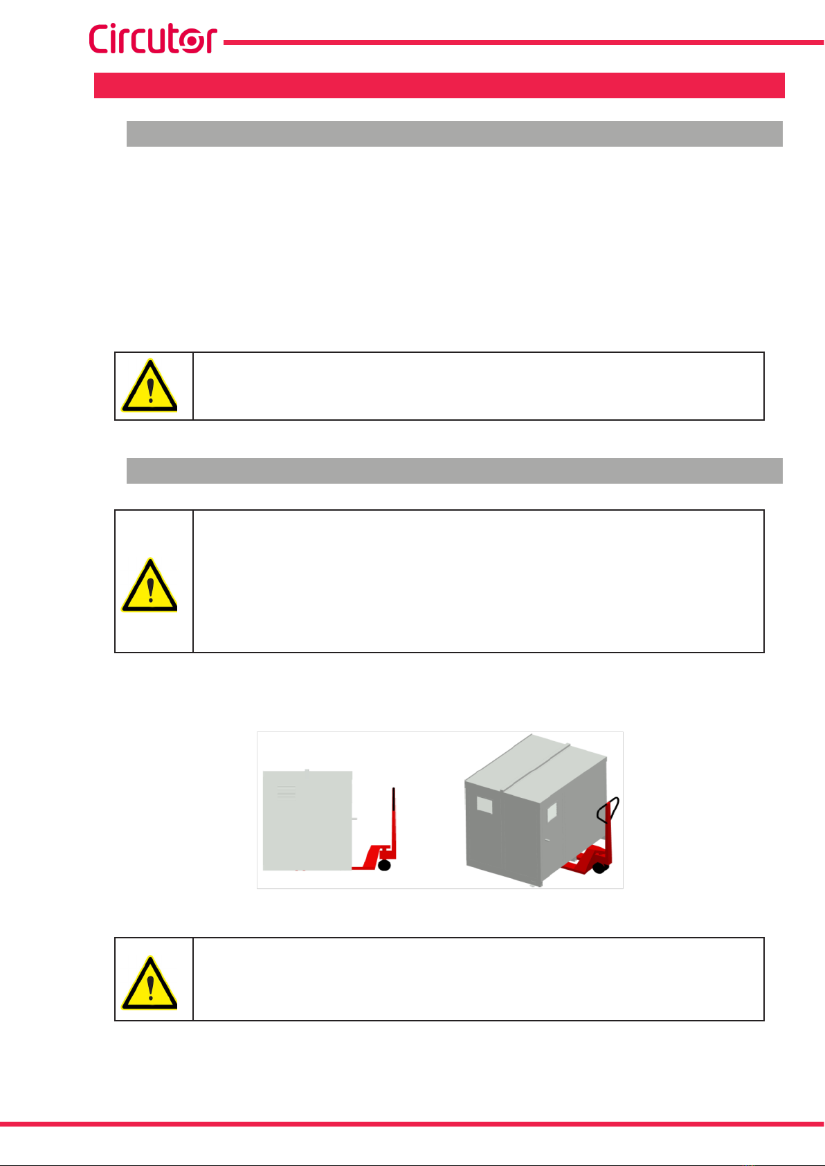
To move the unit a short distance, the unit's oor support proles facilitate handling with a pallet
jack or forklift. (Figure 1)
Figure 1: Transport with pallet jack.
The centre of gravity of some units may be found at a considerable height.
Therefore, when handling with a forklift, it is recommended that the unit be
securely fastened and that no abrupt manoeuvres made. The unit should not
be lifted more than 20 cm off the ground
6
OPTIM HYB Series
Instruction Manual

When unloading and moving the unit, use a forklift with forks long enough to support the entire
length of the base. Otherwise, the forks should be long enough to support at least ¾ of said
depth. The forks must be at and supported rmly by the base. Raise the cabinet by placing the
forks underneath the prole that supports the unit. (Figure 2).
There might be an offset in the centre of gravity from the centre of the cabinet,
as a result of the uneven distribution of loads inside the unit. The necessary
precautions must be taken to prevent the unit from tipping over during abrupt
operations.
Figure 2: Unloading with a forklift.
1.3.- STORAGE
The following storage recommendations must be followed for the hybrid capacitor banks:
Avoid placing them on uneven surfaces.
Do not store them in outdoor areas, humid areas or areas exposed to splashing
water.
Avoid hot spots (maximum ambient temperature: 40 ºC)
Avoid salty and corrosive environments.
Avoid storing the units in areas where a lot of dust is generated or where the risk of
chemical or other types of contamination is present.
Do not place any weight on top of the unit cabinets.
7
Instruction Manual
OPTIM HYB Series

2.- PRODUCT DESCRIPTION
The purpose of this manual is to assist during the installation, start-up and maintenance of
OPTIM HYB series low voltage (LV) capacitor banks with static operation. Carefully read the
manual to achieve the best performance from those units.
2.1.- CAPACITOR BANK COMPONENTS
From the electrical standpoint, the unit is made up of the following blocks:
2.1.1. HYBRID REGULATOR
The hybrid capacitor banks are equipped with Computer HYB hybrid regulators (Figure 3).
Figure 3: Computer HYB Hybrid Regulator.
This regulator has two types of outputs (see the inputs and outputs identied in Figure 4.:
6 relay outputs with operating voltage of 250 V ~. and operating current of 4 A (AC1) for
the auxiliary control voltage of the electromechanical contactors that operate the three-phase
capacitors (three-phase steps of the OPTIM HYB capacitor bank).
24 static outputs to provide a 12 Vdc activation signal to the + and - inputs of the CPC2
connection controller boards at zero voltage difference. These boards control the semiconduc-
tor modules (thyristor-diode) and operate the single-phase capacitors (single-phase steps of
the OPTIM HYB capacitor bank).
The Computer HYB also has the following notable features:
The necessary information to calculate compensation demand by phase is provided by a
CVM-MINI-RS485-model power analyzer via RS-485 communications with the Modbus/RTU
protocol.
8
OPTIM HYB Series
Instruction Manual

The communication parameters installed in the unit are:
Speed: 9600 bps, parity: No, data bits: 8, stop bits : 1
The standard OPTIM HYB models come with the CVM-MINI-RS485 analyzer built into the door
panel and programmed with the above values.
Note: If the OPTIM HYB capacitor bank does not include the CVM-MINI-RS485 analyzer and
you intend to use the existing unit in the installation to be compensated, with an RS-485 output
that is not being used to communicate with any data display system, the RS-485 communica-
tions must be programmed as indicated above.
(For more information, see the CVM-MINI-RS485 instruction manual at www.circutor.com).
The connection terminals for the external RS-485 signal are indicated in Figure 4.
Unit auxiliary power supply: 230 V ~ ± 10 % / 50-60 Hz.
Setpoint value of target cos phi set at 1, individually for each phase.
Regulation with a delay between connections/disconnections (response to compensation de-
mands) differentiated between the single-phase steps operated by semiconductors by default
of 1 s; and the three-phase steps by default of 20 s.
Reactive power compensation algorithm consisting of prioritising the connection of sin-
gle-phase steps to compensate more quickly, and of substituting these connected single-phase
steps for a three-phase step when the compensation needs allow it.
Thus, the connected single-phase steps are replaced with a three-phase power step with an
equivalent phase if 20 s after the last single-phase stage is connected there is an available
three-phase step in the capacitor bank with the same three-phase value for the 3 connected
single-phase stages. In this situation, the single-phase steps would be disconnected and the
three-phase equivalent would be connected at the same time. In this way, the single-phase
stages are again enabled for fast connection if new three-phase or single-phase compensation
demands arise.
LEDs on the front panel indicating the connected stages, CPU operation, communication
status with the CVM-MINI-RS485 and alarm signals. See Figure 5 for a detailed description of
the LEDs on the Computer HYB front panel.
Additional input for RS-485 communications, for programming and control of internal regula-
tor functions
Note: only for use by CIRCUTOR personnel or by those properly trained in its use.
9
Instruction Manual
OPTIM HYB Series

The available combinations for standard models are selected through internal mini-dips.
The programming is done in-factory and should not be modied, except by
CIRCUTOR personnel or by those properly trained in its use.
Note: If you need to nd out the conguration of the mini-dips for each combination, please
contact CIRCUTOR technical assistance.
The available staging combinations as of the date of publication of this manual are exclusively
those indicated in Table 2:
Table 2:Available stage combinations.
Model Composition
OPTIM HYB1-90-440 (3 x 2 x 5) kvar / 230 V + (3 x 15) kvar / 400 V / 50 Hz
OPTIM HYB1-110-440 (3 x 2 x 5) kvar / 230 V + (4 x 15) kvar / 400 V / 50 Hz
OPTIM HYB2-165-440 (3 x 3 x 5) kvar / 230 V + (3 x 30) kvar / 400 V / 50 Hz
OPTIM HYB2-200-440 (3 x 3 x 5) kvar / 230 V + (4 x 30) kvar / 400 V / 50 Hz
OPTIM HYB2-270-440 (3 x 3 x 5) kvar / 230 V + (6 x 30) kvar / 400 V / 50 Hz
OPTIM HYB2-325-440 (3 x 3 x 10) kvar / 230 V + (3 x 60) kvar / 400 V / 50 Hz
OPTIM HYB3-400-440 (3 x 3 x 10) kvar / 230 V + (4 x 60) kvar / 400 V / 50 Hz
OPTIM HYB3-470-440 (3 x 3 x 10) kvar / 230 V + (5 x 60) kvar / 400 V / 50 Hz
OPTIM HYB3-540-440 (3 x 3 x 10) kvar / 230 V + (6 x 60) kvar / 400 V / 50 Hz
Digital input for external temperature relay signal (Figure 4) installed at the top of the heatsink
to dissipate the semiconductors. ( Normally in closed position )
In the event of an alarm, the connected steps would disconnect until the thermal relay returns
to its NC position and the condition triggering the alarm disappears.
The alarm situation is indicated by a combination of lit LEDs on the front panel of the Computer
HYB (See Figure 5).
Lack of compensation alarm, installed in the Computer HYB.
The alarm goes off when the non-compensated three-phase power is greater than 30% of the
total three-phase power available in the capacitor bank, or in other words, is greater than 30%
of its nominal power of 400 V~.
The alarm situation is indicated by the cos φ LED being lit on the front panel of the Computer
HYB. (See Figure 5).
2.1.1.1. Computer HYB Regulator Connections.
Note : See the general connection diagram in “7.- OPTIM HYP TYPE DIAGRAM”
The regulator comes fully connected, expect in the case of units that do not have the CVM-MI-
NI-RS485 analyzer.
In this case, you must connect the CVM-MINI-RS485 communications output to the ASB COM2
terminal of the Computer HYB, using a shielded communication cable with at least 3 wires and
with a section of at least 0.25 mm2.
10
OPTIM HYB Series
Instruction Manual

Any modication to the regulator connections must be performed exclusively
by CIRCUTOR personnel or by those properly trained in its use
The regulator's input and output terminals are shown in Figure 4.
5 C 6 7 8 1 2C C C C C 3 C 4 5 6 7 8C C C C C
1 C 2 3 4 5 6C C C C C 7 C 8 1 2 3 4C C C C C
K4 k5 k6 SC1 A B SA B
L2
L1 L2
L3
K1 k2 k3 C1 LN
OUTPUTS 1 AND 8 PANEL CONTROL CPC4
SINGLE-PHASE STAGES L1
COM1 COM2
OUTPUTS 1 AND 4
SINGLE-PHASE STAGES L2
PANEL CONTROL CPC4
OUTPUTS 1 AND 3
CONTACTORS
CONTROL
SUPPLY
POWER
INPUT SIGNAL
NC THERMAL RELAY
OUTPUTS 5 AND 8
SINGLE-PHASE STAGES L2
PANEL CONTROL CPC4 OUTPUTS 1 AND 8 PANEL CONTROL CPC4
SINGLE-PHASE STAGES L3
OUTPUTS 1 AND 3
CONTACTORS
CONTROL SIGNAL INPUT RS485
FROM CVM-MINI-RS485
AUXILIAR SIGNAL
INPUT RS485
Figure 4: Terminals on the Computer HYB Hybrid Regulator.
2.1.1.2. Indicator LEDs on the Computer HYB regulator.
The Computer HYB regulator has a series of LEDs on its front panel to indicate the connected
stages, CPU operation, communication status with the CVM-MINI-RS485 and alarm signalling.
The different LEDs on the Computer HYB front panel are shown in Figure 5.
Figure 5: LEDs on the Computer HYB Hybrid Regulator.
11
Instruction Manual
OPTIM HYB Series
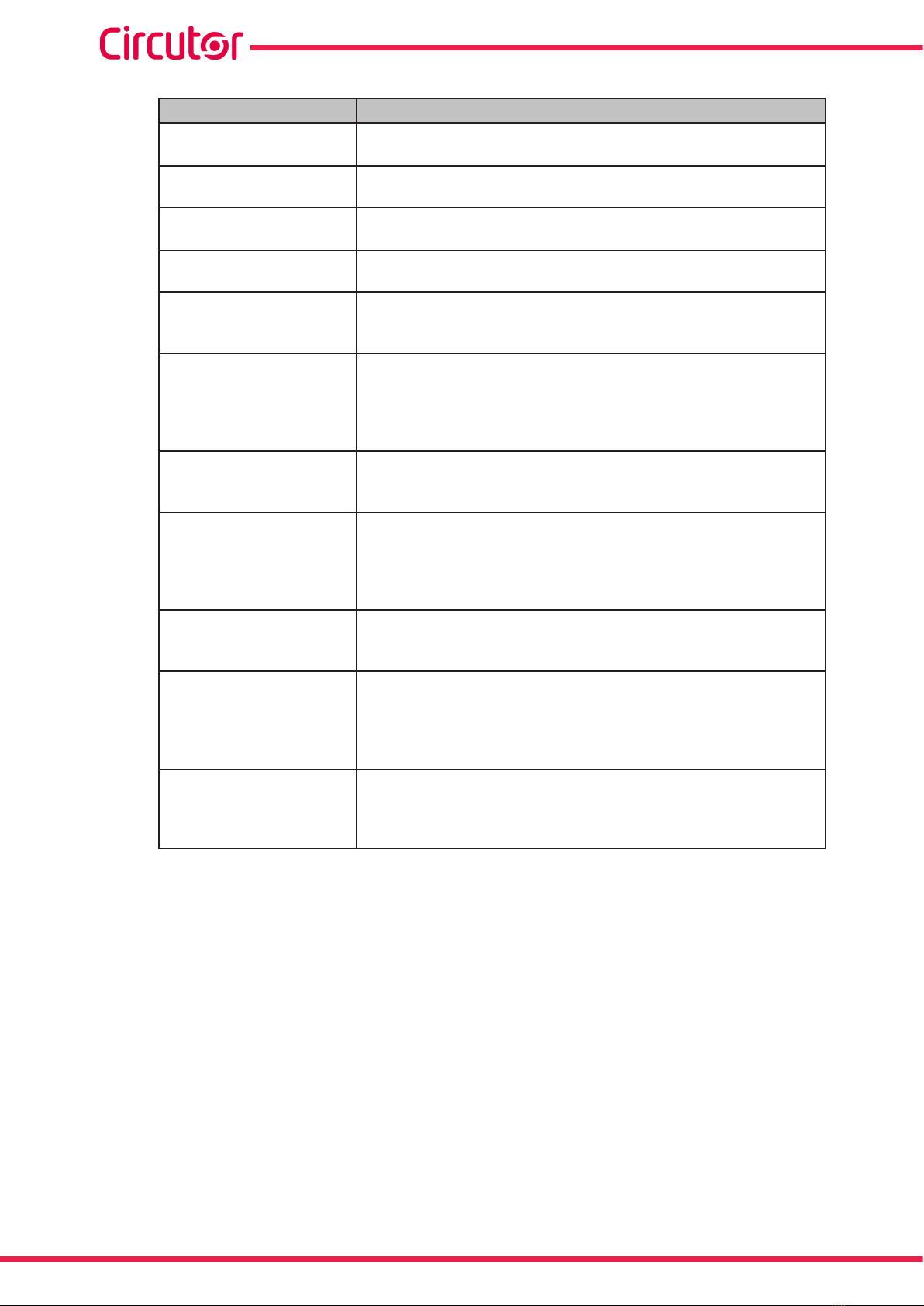
Table 3:LEDs on the Computer HYB Hybrid Regulator.
LED Description
L1/1 ...L1/8 Indicates the activation of the single-phase step between phase L1
and Neutral controlled by that output.
L2/1 ...L2/8 Indicates the activation of the single-phase step between phase L2
and Neutral controlled by that output.
L3/1 ...L3/8 Indicates the activation of the single-phase step between phase L3
and Neutral controlled by that output.
K1...K6 Indicates the activation of the three-phase step controlled by that
output.
RS485 COM 1: RX and TX
Indicates communication with the Computer HYB through the
COM 1 communication channel, which is used for in-factory pro-
gramming.
RS485 COM 2: RX and TX
If the 2 LEDs ash alternately at an approximate rate of once per
second, this indicates the correct functionality of communications
between the Computer HYB regulator and the CVM-MINI-RS485
from which the electrical parameter values are obtained to perform
mains compensation.
CPU
If it ashes at an approximate rate of once per second, this indi-
cates the correct functionality of the Computer HYB regulator's
microprocessor.
cosφ
Indicates the activation of the alarm due to lack of compensation, if
the uncompensated three-phase power is greater than 30% of the
value of the total available three-phase power in the capacitor bank,
which is to say that it is greater than 30% of its nominal power of
400 V ~, for a period of 15 consecutive minutes.
PROG
If pressed while the Computer HYB regulator is connected to the
power supply, the default communication values of the regulator
are restored.
RS485 COM 2 RX and TX
+
L1/2
+
CPU
If these 4 LEDS are ashing at a very fast rate, this indicates a com-
munications problem between the Computer HYB regulator and
the CVM-MINI-RS485.
Check the connection of the RS-485 communication cable and the
conguration of the CVM-MINI-RS485 communication parameters.
L1/3 + CPU
If these 2 LEDs are ashing at a very fast rate, this indicates that
there is an alarm condition due to overheating.
The thermal relay located in the heatsink has been activated, with
its position changing from NC to NO.
2.1.2. CPC2 PANEL: ZERO SWITCHING CONNECTION CONTROL BY TWO SINGLE-PHASE
STAGES
The static capacitor banks come equipped with CPC2 panels in the single-phase stages.
The role of the CPC2 panels is to control the zero switching connection of the thyristor-diode
modules that operate the single-phase stages, preventing connection current transients.
The typical connection diagram of a step can be seen in Figure 6 and with more detail in section
“7.- OPTIM HYP TYPE DIAGRAM”.
The CPC panels are activated via a 12 Vdc signal supplied by the Computer HYB regulator's
outputs. The standard CPC2 panels are designed to always be used between phase and neu-
tral on networks with phase-neutral voltage of Umax = 254 V.
12
OPTIM HYB Series
Instruction Manual

Th-D 1
PPPC1
1 3
2
Q
1
U1
U2
1
32
4
5
Radiador
PLACA
1G1
+
-
CPC2
CONTROL
1K1
12VDC
Alimentación Potencia
Conexión a Condensador Monofásico
Mando
Figure 6: Basic connection diagram of the CPC2 to the power block.
2.1.3. SINGLE-PHASE POWER BLOCK
The single-phase power block of a OPTIM HYB unit consists of 6 to 9 groups of thyristor-diode
semiconductors + single-phase capacitor + unipolar circuit breaker.
Each single-phase group consists of a cylindrical capacitor, an aluminium cylindrical housing, 2
terminals, 1 thyristor-diode module joined to a general heatsink and the appropriate protection
element for the power of the module (unipolar circuit breaker). For more detailed information,
see section “7.- OPTIM HYP TYPE DIAGRAM”.
2.1.4. THREE-PHASE POWER BLOCK
The three-phase power block of a OPTIM HYB unit consists of 3 to 6 groups, each group con-
taining:
13
Instruction Manual
OPTIM HYB Series

1 three-pole electromechanical contactor, appropriate for connecting capacitive loads
(application category AC-6), with a pre-inserted impedance block to limit the capacitor's con-
nection current and fast discharging resistors to ensure a minimal residual voltage in the ca-
pacitor when it is connected.
The contactors have 1 x 230 V / 50-60 Hz (± 10 %) operation coils.
1 three-phase capacitor, in a cylindrical aluminium housing, with a rated voltage of 440 V.
1 three-pole circuit breaker with a calibre suitable for the stage power, with a C Curve and
Ics = 6 kA (400 V).
For more detailed information, see section “7.- OPTIM HYP tYPE DIAGRAM”.
2.1.5. MAINS CONNECTION TERMINALS
The mains connection terminals of a OPTIM HYB unit consist of the input terminals of the quad-
rupole isolating switch, which comes standard with the capacitor bank.
For more detailed information, see section “7.- OPTIM HYP TYPE DIAGRAM”.
14
OPTIM HYB Series
Instruction Manual
3.- INSTALLATION
3.1.- PRELIMINARY RECOMMENDATIONS
In order to use the unit safely, it is critical that individuals who handle it follow the
safety measures set out in the standards of the country where it is being used,
use the personal protective equipment necessary, and pay attention to the vari-
ous warnings indicated in this instruction manual.
Installation or maintenance personnel should read and understand this manual
before operating the unit.
A copy of this manual should always be available to maintenance personnel for
reference purposes
Connecting the unit to the public mains must be carried out in compliance with
the EN-IEC60204-1 standard, regarding the safety of LV electrical installations.
It is recommended that several personnel are present when handling the unit for
installation or maintenance.
If damage or faults are detected during unit operation, or in circumstances that
compromise safety, immediately stop work in that area and disconnect the unit in
order to check it without voltage.
The manufacturer of the unit is not responsible for any damages resulting from failure by the
user or installer to heed the warnings and/or recommendations set out in this manual, nor for
damages resulting from the use of products or accessories that did not come with the unit or
that were made by other manufacturers.
If an anomaly or malfunction is detected in the unit, do not use it to perform any operation.
Modifying, upgrading or rebuilding the unit without written authorisation from the
manufacturer is prohibited.
The installation, operation and maintenance of low voltage (LV) units must only
be carried out by authorised installers. LV regulations (Art. 22) specically dene
the requirements that authorised installers must meet.
Do not access the active elements of a capacitor bank with static operation that
has been powered and might have voltages present. Wait at least 5 minutes af-
ter the power supply has been disconnected.
Do not touch the terminals or active parts of the unit until you have veried that
voltage is not present. If you have to handle or touch the terminals or other control
panel components, use adequately insulated personal protection equipment and
tools.
After any maintenance and before re-connecting the power supply to the unit,
check that its enclosure is properly closed and that no items or tools were left
inside that could cause a short-circuit.
15
Instruction Manual
OPTIM HYB Series

Do not disconnect the current transformer secondary without short-circuiting it
rst. The operation of a current transformer with an open secondary will cause an
overvoltage that could damage it and electrocute the person handling it.
3.2.- PREPARATION
The CIRCUTOR OPTIM HYB static capacitor banks come ready for easy installation and start-
up.
Remove the packaging of the unit and verify that its electrical features are suitable for connec-
tion to the available mains. To do so, check the features label located inside the cabinet next to
the regulator, see Figure 7 .
Key data to be checked:
Mains frequency and voltage, Un / fn.
Nominal power of the capacitor bank, Qn (kvar) and composition
Current consumption, Imax . This current must be considered to select the proper size
of the power supply cable of the unit and ultimately the circuit breakers and protection
elements to be connected in front of it.
Environmental conditions. (See “6.- TECHNICAL FEATURES”)
Figure 7: Features label.
3.3.- INSTALLATION LOCATION
It is important to maintain a minimum distance around the unit to facilitate cooling.
In self-supporting cabinets, the back and front sides of the cabinet must be kept at least 50 cm
away from walls of other units and other infrastructure to allow for ventilation.
In terms of the side walls, it is recommended that a separation of 10 cm be maintained between
adjacent cabinets.
On wall-mounted cabinets, it is recommended that at least 20 cm of separation be maintained
between the sides of adjacent cabinets.
Note: Hybrid units have aluminium heatsinks to cool the thyristors. Periodically clean these
radiators with a brush or with compressed air and ensure that they have maximum ventilation.
16
OPTIM HYB Series
Instruction Manual
Make sure the unit can be accessed easily.
The environmental conditions of the location where the unit is installed must not exceed the
limits set forth in the technical features (See “6.- TECHNICAL FEATURES”)
To ensure proper ventilation, the unit must be installed in a vertical position.
In accordance with LVR, once the unit is installed, it must be protected against direct and indi-
rect contacts; therefore, a circuit breaker and earth leakage protection for the capacitor bank
power supply line should be installed.
3.4.-CONNECTION OF THE CAPACITOR BANK TO THE MAINS
Check that the rated voltage of the capacitor bank matches the voltage between
phases of the grid to which it is being connected.
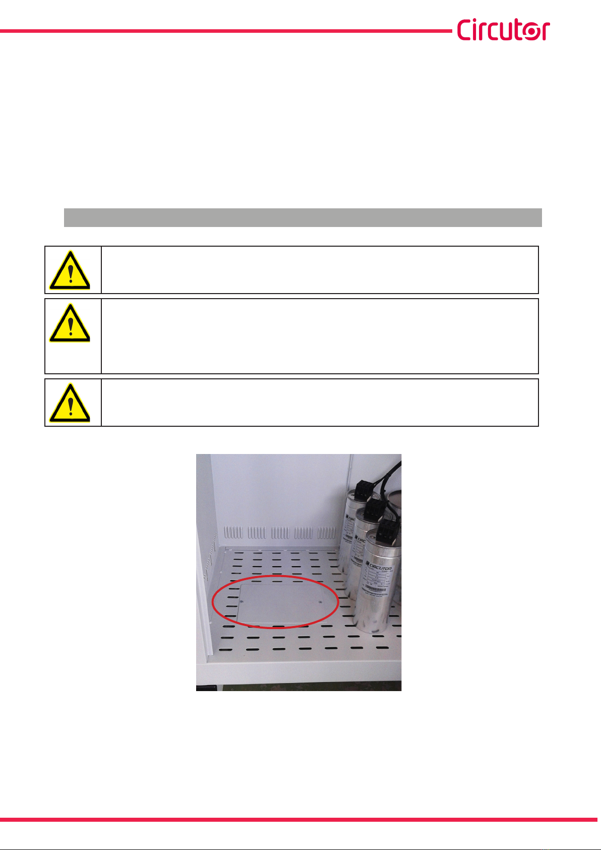
For feeding cables into the capacitor bank cabinet, always use the entry point
enabled for this purpose (See Figure 8 showing the cable entry point on OPTIM
HYB 2 models).
If another part of the cabinet is cut out to be used for cable entry, the CIR-
CUTOR manufacturer's guarantee shall be rendered void.
Do not cut holes in other parts of the cabinet for feeding cables through or for
installing support brackets.
It may produce trimmings that can cause short-circuits.
Figure 8: Cable entry point on the OPTIM HYB 2 model.
17
Instruction Manual
OPTIM HYB Series
3.5.-POWER CIRCUIT
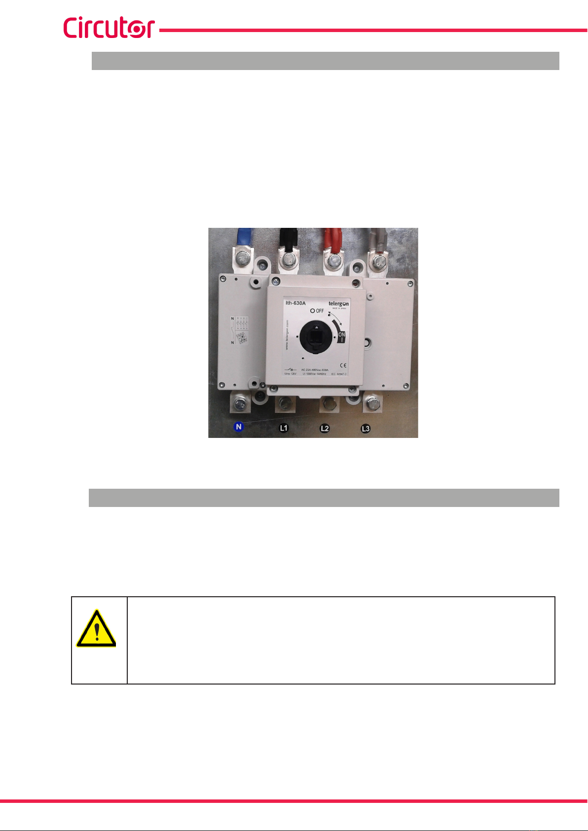
Connect input terminals L1, L2, L3 and N (power circuit) to the mains using a cable with a prop-
er section width, in accordance with the LVR, ITC-BT-19.
Generally, the cables of the phases are according to the following colour code: L1 (black), L2
(brown), L3 (grey) and the neutral conductor N (blue).
To determine the size of the phase cables, the maximum nominal current Imax shown on the unit
label and a transient overload of up to 1.5 times Imax be taken into account. The neutral cable
must have the same section as the phase conductor.
Figure 9: Input terminals L1, L2, L3 and N for connecting OPTIM HYB capacitor banks to the mains.
3.6.- EXTERNAL ISOLATION AND PROTECTION ELEMENTS
The capacitor bank has a manual internal quadrupole isolator, but it must be connected to a
line that is protected by a circuit breaker as well as earth leakage protection at the header, in
accordance with Spanish Low-Voltage Electrotechnical Regulations (LVR) and depending on
the earthing system of the installation.
The protection elements, isolation switches and/or switches that are added exter-
nally to the capacitor bank must be of a minimum size to withstand a current 1.5
times greater than what is indicated on the label (LVR, ICT-BT-48)
If an earth leakage protection for the capacitor bank is installed, its sensitivity and
trip delay must be adjustable.
18
OPTIM HYB Series
Instruction Manual

3.7.- AUXILIARY CONTROL VOLTAGE
Standard OPTIM HYB capacitor banks for 3 x 400 V / 1 x 230 V networks do not require an
auxiliary power supply.
3.8.- EARTH CABLE CONNECTION
Connect the earth terminal of the capacitor bank housed inside the operations panel of the unit
(see Figure 10) to the exterior earth connection.
The earth cable section must be selected in accordance with the admissible current limits es-
tablished in the LVR (ITC-BT-19 – Indoor or receiver installations).
Figure 10: Earthing terminal for external earthing connection of the OPTIM HYB capacitor banks
3.9.- CURRENT TRANSFORMER (CT) CONNECTION
For standard units that come with a CVM-MINI-RS485 power analyzer: You
must place 3 current transformers (CT) outside the capacitor bank, one at
each phase, measuring the total current of the load plus the capacitor bank
itself (Figure 11).
The standard transformer must have a nominal output of 5 A at the secondary.
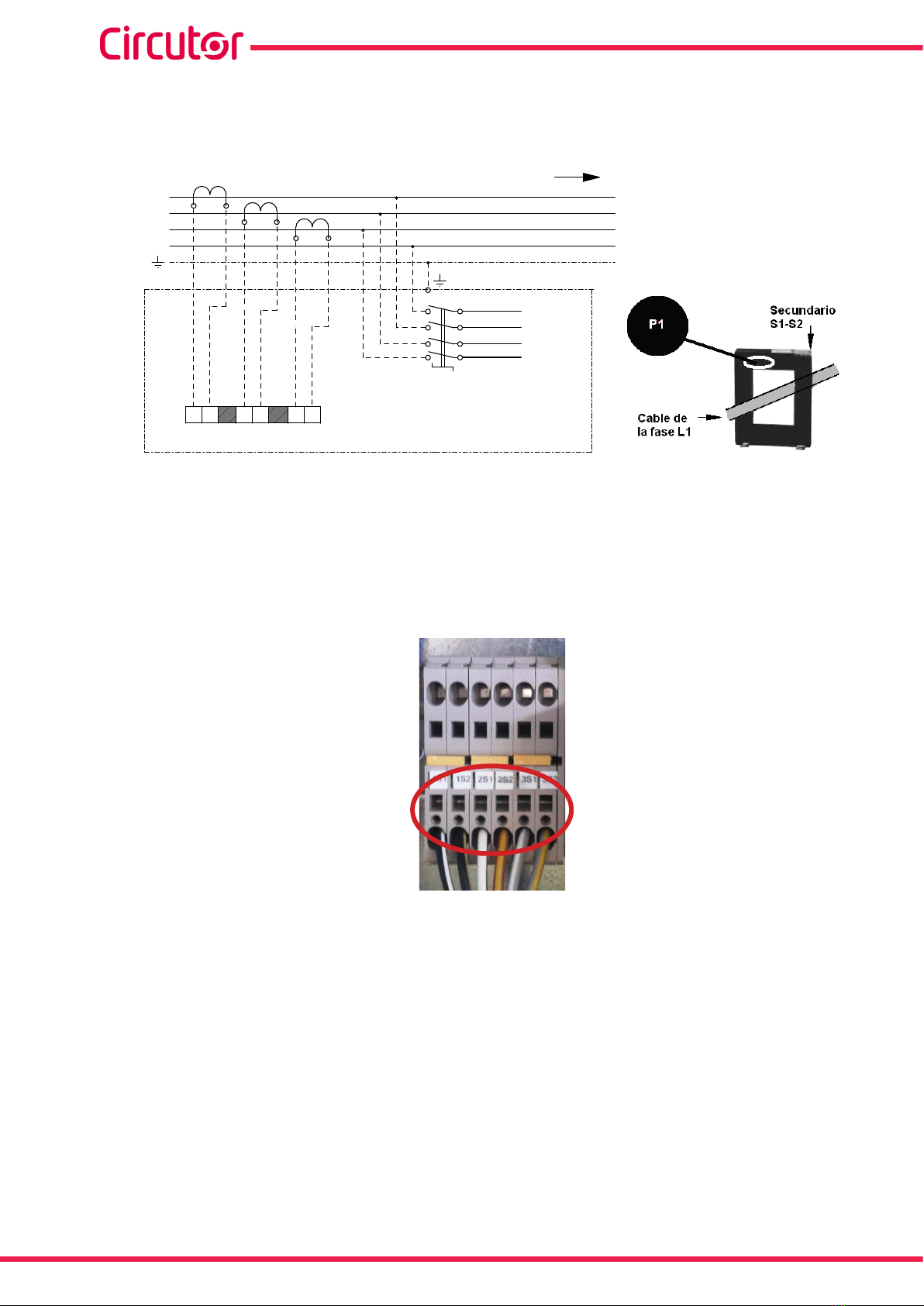
For correct measurement of powers and angles, you must connect the CT to
each phase with the direction of the current from P1 to P2 (Figure 11) and connect
the secondary (terminals S1, S2) to the terminals with the same name on the ca-
pacitor bank (see Figure 11 and Figure 12).
Avoid the ow of current through the CT's primary before connecting the second-
ary to the S1 and S2 terminals of the capacitor bank.
If the CT must be installed while the installation is under load, short-circuit S1 and
S2 while they are not connected to the capacitor bank.
19
Instruction Manual
OPTIM HYB Series
The current value of the CT primary winding must be equal to or slightly greater than the size of
the mains switch of the installation. Therefore, the CT must be able to measure the maximum
current expected to be consumed by all the loads being compensated.
L1
L2
L3
N
RED CARGA
3x400 V / 1x230 V - 50 Hz
L1
L2
L3
S1
N
TB1
BATERÍA DE
CONDENSADORES
1S1 1S2
S1 S2
S1 S2
S1 S2
T.I.1
T.I.2
T.I.3
2S1 2S2 3S1 3S2
Figure 11: Installation of external current transformers (CT).
The connection point of the CT for a capacitor bank that compensates an entire installation is
after the mains switch of the installation.
To prevent excessive attenuation of the signal, it is recommended that the minimum secondary
section winding cable size (terminals S1, S2) is at least 2.5 mm2.
Figure 12: Current transformer (CT) connection terminals.
Once the cables are installed, disconnect the jumper connecting the 3 S1 and S2 terminals of
the capacitor bank (see Figure 13)
20
OPTIM HYB Series
Instruction Manual
This manual suits for next models
9
Table of contents
Other Circutor Industrial Electrical manuals


Popular Industrial Electrical manuals by other brands

TeeJet Technologies
TeeJet Technologies e-ChemSaver 115880 Maintenance instructions

Murata
Murata GRM188R61E475KE11 Series Reference sheet

Murata
Murata GRM188C71A475ME11 Series Reference sheet

Murata
Murata GRM216R71H331KA01 Series Reference sheet

Murata
Murata GRM188R71E682KA01 Series Reference sheet

Emerson
Emerson Liebert NXL Product specification/installation sheet


