*OM101-AUI mating connector and mounting clip. (not
General
DESCRIPTION LED INDICATORS (cont) supplied )
Operating temperature...................... -40°C to +75°C
The OM101-AUI media converter has one optical 100BASE- O-FEF: ON indicates a receive fault at the remote
Humidity (RH) ................................... 0% to 95%
FX port and one electrical 10BASE-AUI (MAU) port. It end of the optical link. FLASHING indicates
MTBF ................................................ > 50,000 hrs
connects a 10BASE-AUI (DTE) device to a 100BASE-FX no optical link. The remote fault indicator
Dimensions ....................................... 6.5 * 1.8 * 10 cm
device over a pair of optical fibers. The AUI port connects to functions only with Ethernet devices that
any IEEE 802.3 (Ethernet) compatible card with an AUI (DTE) support far-end fault detection.
interface. It operates in an manner similar to a 10BASE-FL ELECTRICAL SIGNAL I/O
transceiver except for the conversion to 100BASE-FX. Bad AUI-OUT: FLASHING indicates data is being CLOSED OPEN
packets and collisions are not repeated. The DB-15 male I/O connector pin-outs correspond to the transmitted by the AUI port.
IEEE 802.3 standard for Media Attachment Units (MAU). The To lock into postion slide retaining clip to the right. To
It can be connected to an OM101 to create a 10BASE-AUI to OM101-AUI connects to a DTE AUI device with a straight AUI-IN: FLASHING indicates data is being received release, slide the clip to the left.
100BASE-TX fiber optic bridge. through AUI cable. The table below gives details of this by the AUI port.
connection.
The 10 Mbps AUI port operates in half-duplex. The 100 Mbps AUI-COL: FLASHING indicates a collision on the AUI
fiber port operates in full-duplex. port.
SWITCHES
The OM101-AUI is available with ST or SC connectors; and
for singlemode or multi-mode fiber.
The OM101-AUI has a set of switches located on the end
panel. The switch functions are as follows:
APPLICATIONS
SQE/DSQE: The DSQE position disables the Signal
Connection of legacy 10 Mbps devices to 100 Mbps Quality Error signal (heart beat) on the AUI
devices port. The SQE position enables the signal.
Noisy RFI environments - factory floor This signal provides an indication to the DTE
device that the MAU interface is working
Secure data environments POWER CONNECTION properly. The signal should be enabled if the
DTE device requires it.
FEATURES Power is derived the AUI interface.
SPR: Unused.
802.3 compatible
FIBER CABLES
ST or SC connector INSTALLATION
Single or multi-mode fiber option The OM101-AUI media converter is designed to work with
Low EMI 62.5µ core fibers, terminated with ST connectors at both 1. Connect the OM101-AUI to the DTE AUI device with an
ends. Fibers with 100µ core will work, however some optical AUI cable and fasten into position if needed (*see
SPECIFICATIONS attenuation may have to be added to insure the receiving opposite page). The O-FEF indicator should flash.
modem is not overloaded (-14.dBm max). Fibers with 50µ
Optical core will also work, however the smaller core allows about 4 2. Connect the RX fiber of the OM101-AUI to the TX fiber of
dBs less light into the fiber. This degrades the allowable link the remote device. The O-LINK LED should turn on. The
Light source ......................... 1300 nm LED MM version loss from 13.5 dBs to 9.5 dBs. O-FEF LED will stop blinking and turn on if the remote
1300 nm LASER SM version device has far-end fault support. Otherwise, it should
Optical output (62.5/125 fiber) MM version .......... -19 dBm turn off. Connect the TX fiber of the OM101-AUI to the
LED INDICATORS
Optical output (9/125) SM version........................ -18 dBm RX of the remote device. The O-LINK LED should be on
Photo detector...................................................... PIN Si
-10 and the O-FEF LED should be off.
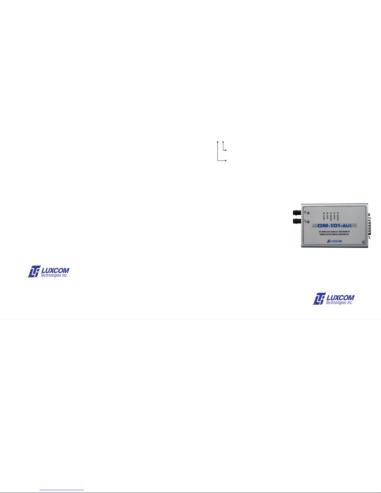
The OM101-AUI has five status indicators LEDs on the top,
Optical sensitivity (10 BER) ................................ -32.5 dBm and five on the end panel. The functions of which are as
Optical connectors ............................................... SC or ST 3. Once the O-LINK indicator is on and the O-FEF indicator
follows:
is off, the modem is fully functional
Electrical O-LINK: ON indicates a good optical link between the
OM101-AUI and the opposite device.
Data standards ................................. IEEE 802.3 MAU
Data I/O connector............................ DB-15M
Power source ................................... AUI 12V DC
Power consumption ......................... 2.6 Watts
DB-15P IEEE 802.3 NAME FUNCTION SIGNAL DIRECTION
I/O
To OM101-AUI From OM101-AUI
3 DO + (Data Out +) Transmit X
10 DO - (Data Out -) Pair X
11 DO S (Data Out Shield) X
5 DI + (Data In +) Receive X
12 DI - (Data In -) Pair X
4 DI S (Data In Shield) X
2 CI + (Control Out +) Collision X
9 CI - (Control Out -) Pair X
1 CI S (CI Shield) X
6 VC (Voltage Common) Power X
13 VP (Voltage Plus) Pair X
14 VS (Voltage Shield)