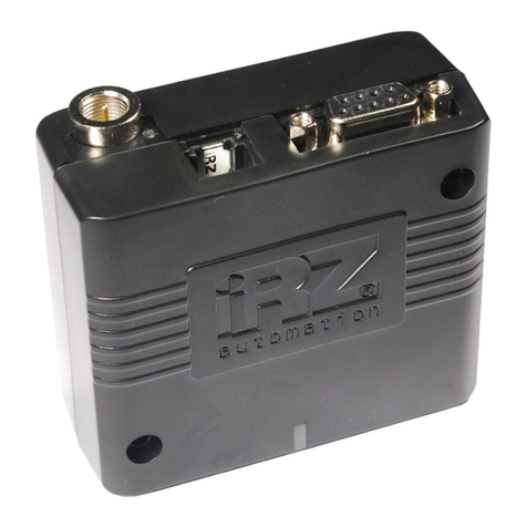
Circutor ZDU E-GSM-PLUS-V User manual

DESCRIPTION1.
The ZDUE-GSM-PLUS-V meter modem is designed for the remote reading
of electronic meters with serial interfaces via the GSM network. Data are
exchanged over the interfaces via the telephone line in transparent mode at
a xed baud rate or in accordance with IEC62056-21.
SAFETY NOTES2.
¡IMPORTANT!
The unit’s protection systems might not be effective if the unit is used for
purposes other than those specied by the manufacturer.
¡IMPORTANT!
Before starting any maintenance, change in connections, repair, etc, it
must be disconnected from all power sources. When an operating fault or
protection fault is suspected, the equipment must be taken out of service.
The equipment is designed to be quickly replaced in the event of any
breakdown.
General lnformation: The ZDUE-GSM-PLUS V is compliant with the Euro-
pean EN 60950 standard, Safety of information technology equipment.
The ZDUE-GSM-PLUS V has been designed exclusively for permanent ins-
tallation and only professionally trained electricians are authorized to perform
such an installalion according lo the generally accepted technical rules and
regulations governing the setting up of telecommunications equipment and
end devices.
The ZDUE-GSM-PLUS V is not des igned to be connected to IT systems lor
electrical energy supply.
Please read through these installation instructions carefully befare using
the device.
Dlsconnection from the power supply circuit : An easily accessible,
all-pole circuil breaker in the power supply circuít is required for the house
installation. Altematively, a single-pole círcuit breaker can be used in the
outer conductor as long as a distinct neutral conductor has been integrated
into the supply line. In Germany. the circuit breaker must at least meet the
requirements of the DIN VDE series 0100 standard.
Installation fuse: For the house installalion, there must be an installation
fuse that cornplies with lhe DIN VDE series 0100 standard and is properly
adapted to the cable crosssection of the power supply line. The additional
short-circuit protection must have a selectivity of I≥ 1500 A.
Strain relief: For the house installation, the lines leading to Ihe ZDUE-GSM-
PLUS V must be protected with an adequate strain relief.
Mounting the antenna : When the antenna that is included wilh Ihe device
is mounted outdoors, lt is absolutely essential that the antenna is mounted
in the bracket by a qualied professional .
Requirements include adherence to the VDE V 0185 Lightning Protection
Standard . Parts 1 to 4, in its current version and any other relevant stan-
dards .
Important:
The Building Lightning Protection Class (SK): When the anlenna is mounted
outdoors, it can only be set up in lightning protection zones O/E or 1. These
lightning protection zones are specied by the lightning protection sphere’s
radius,
The EMC-compliant líghtníng protectíon zone concept must be observed. In
order to avoid large induction loops, make sure to use lightning protection
potential equalization. If the antenna or the antenna cable is mounted near
lhe lightning protection device, minimum distance to the lightning protectíon
device must be observed. If this is not possible, then an insulated installation,
as described in the VDE V 018 5 Lightning Proleclion Standard, Parts 1 to 4,
in its current version, is required.
Uses: The ZDUE-GSM-PLUS V is a device designed for the remote inquiry
and the remote monitoring of electricity, heat, gas and water meters. lt is
design lo be used in GSM networks.
H
A
B
C
D
E
G
AStatus LEE
BSIM card holder
CDIP switch
DGSM status/error LED
E232 interface
Gterminal bock
HCL jumper
OPENING THE DEVICE3.
In order to insert the SIM card or alter the device settings,you rst have to
open the device:
First disconnect all the poles af the device from the eleclricity supply if il •
is plugged in there.
Now unscrew the screw in the terminal cover and remove the cover.•
Now remove lhe device lid•
ALTERING THE DEVICE SETTINGS4.
The basic settings of the ZDUE-GSM-PLUS V are made with Ihe DIP swit-
ches [C] inside the device. Selecl the desired settings before you connect
the device.
1 2 3 4 5 6 7 8 9 10 Setting
0Meter mode active
1AT mode active
0Paswoord protection OFF
1Paswoord protection ON
0 0 0 PIN = 0000
1 0 0 PIN = 1360
0 1 0 PIN = 8956
1 1 0 PIN = 0934
0 0 1 PIN = 4591
1 0 1 PIN = 6520
0 1 1 PIN = 3298
1 1 1 PIN = 2783
0 0 0 Local bit rate 300 bps
1 0 0 Local bit rate 1200 bps
0 1 0 Local bit rate 2400 bps
1 1 0 Local bit rate 4800 bps
0 0 1 Local bit rate 9600 bps
1 0 1 Local bit rate 19200 bps
0 1 1 Local bit rate 38400 bps
1 1 1 reserved
0Mode C operation ON
1Mode C operation OFF
0Data format 7E1 local / GSM
1Data format 8N1 local / GSM
ZDU E-GSM-PLUS-V
modem GSM
Installation Manual

SETTING THE PIN OF THE SIM CARD5.
In order lo operate the ZDUE-GSM-PLUS-V, you wlll require a 3 V plug- in
SIM card from a GSM network oparator. Set the PIN number of lhe SIM card
to one of the possible 8 that you can also set for the ZDUE-GSM-PLUS-V
with the DIP swilches [3:5] .
INSERTING THE SIM CARD6.
Insert the SIM card as lollows:•
1. Open (he SIM card holder by gently pressing the lid towards the edge •
of the device , ip it up and insert the SIM card inlo the slot in lhe holder.
The gold-plaled contacts on the SIM card have lo lie on the gold-plated
contacts of the holder when the holder is closed. Close the lid of the SIM
card holder and lock il by pressing it gentty back towards the center of the
device. You wltl feel it click into place.
2. Now replace the device lid and the terminal cover.•
CONNECTING THE DEVICE7.
First connect the meter to the device and then connect the power supply.
The device is equipped with 3 different meter interfaces. Only one of them
can be used at any one time.
RS-232 interface (RJ45- Jackl)
PIN Signal Description
2DCD Salida: activa para conexión GSM
4GND Tierra / Neutro
5TXD Salida ; datos al contador
6RXD Output: datos del contador
Señales y niveles de acuerdo con V.24 / V.28.
Todos las demás entradas están reservadas
RS-485 in lerfa ce (terminal block ):
Signal Description
RT- Negative RS·485 interface signal
RT+ Pcsitive RS-485 interface signal
Dual-wire RS-485 interface to connect up to 32 transceivers. The bus connection is
terminated lo
Z=120 Ohms (nominal) (RT+ to RT-) and the cable length is limited lo 1000 m.
CL1 interface (terminal block):
Signal Description
RTX- Negative Cl 1 interface signal
RTX+ Positive Cl 1 interface signal
20mA power interface (current loop) lo connect meters with the power supply interface
according 10 DIN EN 62056-21. Approx. 4 meters can be connected to this interface.
Important :
If the CL1 interface is not in use, insert Jumper [H]. Otherwise. the other Interfaces wlll
not operate.
Auxiliay power source (terminal block ) :
Signal Description
HS- Negative pole of the auxiliary power supply
HS+ Positive pole of the auxiliary power supply
Auxliary power supply of 12 V / max. 100 mA.
The auxiliary power supply is not avallable for all the ZOUE-GSM-PLUSV models.
Power supply (terminal block):
Signal Description
LAC: Unom = 100 ... 230 Vac
DC: Unom = 60 ... 100 Vdc
N
Inom = 42 ... 84 mA
CONNECTING THE ANTENNA8.
The antenna is connected to the Type FME antenna jack. The antenna
should be installed to ensure adequate signal quality. Make sure that there
are no large metal objects (e.g. reinforced concrete) near the antenna, since
they will have an adverse affect on signal quality.
Please observe the safety instructions al the beginning of this manual when
installing the antenna. Have this installation done by a qualied professional!
Be sure to observe the instructions included with your antenna.
LIGHT-EMITTING DIODES (LEDS)9.
Status LED LED (A) Green on Power supply available
GSM status
/error
LED (D) Orange nashing - Error, e.g. PIN error (3.75 s ON /250
ms OFF)
- Network search
- Field strenglh (1..4 times ashing
(each time 250 ms ON) within 2 s)
Orance on GSM-Connect
CONNECTIONS10.
RJ 45 ( Modem) DB9 Hembra RS-232 (CWT) R11 (CWT)
PIN 4 5PIN 1 Y 6 (Puente)
PIN 5 2PIN 2
PIN 6 3PIN 3
Puente 4 – 6
Puente 7 -8
TECHNICAL SERVICE11.
CIRCUTOR SAT: 902 449 459 (SPAIN) / (+34) 937 452 900 (rest of the world)
CIRCUTOR SA - Servicio Posventa
Vial Sant Jordi, s/n
08232 - Viladecavalls (Barcelona)
Tel: (+34) 937 452 900 - Fax: (+34) 937 452 914
e-mail : central@circutor.es
Manual Code:M98228701-03_09A
Table of contents
Other Circutor Modem manuals
