Circutor CEM M-RS485 User manual
INSTRUCTION MANUAL
(M014B01-03-15A)
Communications interface
CEM M-RS485

2
CEM M-RS485
Instruction Manual

SAFETY PRECAUTIONS
DISCLAIMER
CIRCUTOR, SA reserves the right to make modi cations to the device or the unit speci ca-
tions set out in this instruction manual without prior notice.
CIRCUTOR, SA on its web site, supplies its customers with the latest versions of the device
speci cations and the most updated manuals.
www.circutor.com
DANGER
Warns of a risk, which could result in personal injury or material damage.
ATTENTION
Indicates that special attention should be paid to a speci c point.
Follow the warnings described in this manual with the symbols shown below.
If you must handle the unit for its installation, start-up or maintenance, the following
should be taken into consideration:
Incorrect handling or installation of the unit may result in injury to personnel as well as damage
to the unit. In particular, handling with voltages applied may result in electric shock, which may
cause death or serious injury to personnel. Defective installation or maintenance may also
lead to the risk of re.
Read the manual carefully prior to connecting the unit. Follow all installation and maintenance
instructions throughout the unit’s working life. Pay special attention to the installation stan-
dards of the National Electrical Code.
Refer to the instruction manual before using the unit
In this manual, if the instructions marked with this symbol are not respected or carried out correctly, it can
result in injury or damage to the unit and /or installations.
CIRCUTOR, SA reserves the right to modify features or the product manual without prior noti cation.
3
Instruction Manual
CEM M-RS485

CONTENTS
SAFETY PRECAUTIONS ���������������������������������������������������������������������������������������������������������������������������������������3
DISCLAIMER ����������������������������������������������������������������������������������������������������������������������������������������������������������3
CONTENTS�������������������������������������������������������������������������������������������������������������������������������������������������������������4
REVISION LOG�������������������������������������������������������������������������������������������������������������������������������������������������������5
1�- VERIFICATION UPON RECEPTION����������������������������������������������������������������������������������������������������������������� 6
2�- PRODUCT DESCRIPTION��������������������������������������������������������������������������������������������������������������������������������6
3�- UNIT INSTALLATION ����������������������������������������������������������������������������������������������������������������������������������������7
3�1�- PRELIMINARY RECOMMENDATIONS ����������������������������������������������������������������������������������������������������� 7
3�2�- INSTALLATION ������������������������������������������������������������������������������������������������������������������������������������������8
3�3�- UNIT TERMINALS��������������������������������������������������������������������������������������������������������������������������������������9
3�4�- CONNECTION DIAGRAM������������������������������������������������������������������������������������������������������������������������10
4�- OPERATION ��������������������������������������������������������������������������������������������������������������������������������������������������� 11
4�1�- OPERATING PRINCIPLE������������������������������������������������������������������������������������������������������������������������� 11
4�2�- LED INDICATORS������������������������������������������������������������������������������������������������������������������������������������ 11
4�3�- OPTICAL COMMUNICATIONS PORT ����������������������������������������������������������������������������������������������������� 12
4�4- RS-485 COMMUNICATIONS���������������������������������������������������������������������������������������������������������������������12
4�4�1�- MODBUS PROTOCOL���������������������������������������������������������������������������������������������������������������������� 12
4�4�2�- READ COMMANDS �������������������������������������������������������������������������������������������������������������������������� 12
4�4�3�- WRITE COMMANDS ������������������������������������������������������������������������������������������������������������������������� 13
4�4�4�- VARIABLES MODBUS���������������������������������������������������������������������������������������������������������������������� 14
5�- TECHNICAL FEATURES ��������������������������������������������������������������������������������������������������������������������������������19
6�- MAINTENANCE AND TECHNICAL SERVICE������������������������������������������������������������������������������������������������ 21
7�- GUARANTEE���������������������������������������������������������������������������������������������������������������������������������������������������21
8�- CE CERTIFICATE��������������������������������������������������������������������������������������������������������������������������������������������22
NB: The images of the units are solely for the purpose of illustration and may differ from the
original unit.
4
CEM M-RS485
Instruction Manual

REVISION LOG
Table 1: Revision log�
Date Revision Description
07/14 M014B01-03-14A Initial Version
01/15 M014B01-03-15A Changes in the following sections:
4.4.4.
5
Instruction Manual
CEM M-RS485

1�- VERIFICATION UPON RECEPTION
Check the following points upon receiving the unit:
a) The unit meets the specications described in your order.
b) The unit has not suffered any damage during transport.
c) Perform an external visual inspection of the unit prior to switching it on.
d) Check that it has been delivered with the following:
- An installation guide,.
If any problem is noticed upon reception, immediately contact the transport
company and/or CIRCUTOR's after-sales service.
2�- PRODUCT DESCRIPTION
The CEM M-RS485 optical-electric interface converts the optical service port of any unit of the
CEM range into an RS-485 port with MODBUS protocol.
The unit features:
- 3 indicator LEDs: POWER, LINK and COMS.
The unit is installed on 2-step DIN rails, on the left of any unit of the CEM range.
6
CEM M-RS485
Instruction Manual
3�- UNIT INSTALLATION
3.1.- PRELIMINARY RECOMMENDATIONS
In order to use the unit safely, it is critical that the individuals who handle it fol-
low the safety measures set out in the standards of the country where it is being
used, use the necessary personal protective equipment and pay attention to the
various warnings indicated in this instruction manual.
The CEM M-RS485 unit must be installed by authorised and qualied staff.
The power supply plug must be disconnected before handling, altering the connections or
replacing the unit. It is dangerous to handle the unit while it is powered.
Also, it is critical to keep the cables in perfect condition in order to avoid accidents, personal
injury and damage to installations.
The manufacturer of the unit is not responsible for any damage resulting from failure by the
user or installer to observe the warnings and/or recommendations set out in this manual, nor
for damage resulting from the use of non-original products or accessories or those made by
other manufacturers.
If an anomaly or malfunction is detected in the unit, do not use the unit to take any measure-
ments.
Inspect the work area before taking any measurements. Do not take measurements in dan-
gerous areas or where there is a risk of explosion.
Disconnect the unit from the power supply (unit and measuring system power
supply) before maintaining, repairing or handling the unit's connections.
Please contact the after-sales service if you suspect that there is an operational
fault in the unit.
7
Instruction Manual
CEM M-RS485

3.2.- INSTALLATION
On the side of the unit are all of the indications adjusted to the CEI 62052-11 standard.
The unit is installed on a DIN rail.
Before connecting the unit, you must couple it to a CEM energy meter as shown in Figure 1
and Figure 2.
Figure 1: Coupling the CEM M-RS485 to a CEM energy meter�
Figure 2: Coupled CEM M-RS485 and CEM�
Terminals, opening covers or removing elements can expose parts that are
hazardous to the touch while the unit is powered. Do not use the unit until it is
fully installed.
8
CEM M-RS485
Instruction Manual

The unit must be connected to a power circuit that is protected with gL fuses (IEC 269) or
M fuses, with a rating of 0.5 to 2 A. It must be tted with a circuit breaker switch or equiva-
lent device for disconnecting the unit from the power supply mains.
The RCCB or equivalent device must be in the immediate vicinity of the unit and must be
easily accessible.
The power circuit is connected with a cable with a section measuring up to 2.5 mm2.
The RS-485 connector enables cables of up to 1.5 mm 2 to be inserted.
The unit's operating temperature is between -25ºC and +70ºC; always use con-
nection cables that can withstand these temperatures.
3.3.- UNIT TERMINALS
Table 2:List of CEM M-RS485 terminals�
Unit terminals
1: Auxiliary power supply. 3: A(+), RS-485
2: Auxiliary power supply. 4: B(-), RS-485
1 2
3 4
Figure 3:CEM M-RS485 terminals�
9
Instruction Manual
CEM M-RS485
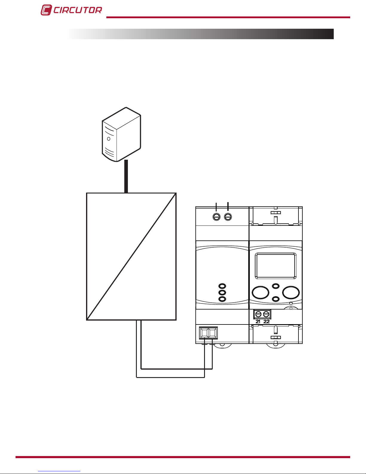
3.4.- CONNECTION DIAGRAM
The RS-485 cable must be made up of a twisted pair cable with a braided shield with a
maximum distance of 1,200 metres between the CEM M-RS485 and the master unit.
A maximum of 32 units can be connected to this bus.
Use an intelligent RS-232 to RS-485 network protocol converter to establish communications
with the master unit.
PC
B(-)A(+)
RS-485
CEM M-RS485
Alimentación
Power Supply
A(+) B(-)
RS-232 / USB / Ethernet / Profibus ...
RS-485
RS-485
RS-232
USB
Ethernet
Profibus
...
Figure 4: CEM M-RS485 connection diagram�
10
CEM M-RS485
Instruction Manual
4�- OPERATION
The CEM M-RS485 is designed to be used as a RS-485 electrical port for any device in the
CEM family, using the mechanical coupling next to the optical port.
4.1.- OPERATING PRINCIPLE
The CEM M-RS485 is an optional accessory for electrical energy meters from the CEM range
that are mounted on DIN rails.
The CEM M-RS485 provides CEM units with RS-485 communications with the MODBUS
protocol.
Once the unit is coupled to the CEM energy meter (See “3.2.- INSTALLATION”) the LINK LED
turns green to let the user know that the link has been made correctly.
From this point onward, the new CEM energy meter + CEM M-RS485 assembly functions as
a single device.
This assembly operates the same as any standard slave device with a RS-485 bus, responding
to MODBUS requests from the bus's master peripheral.
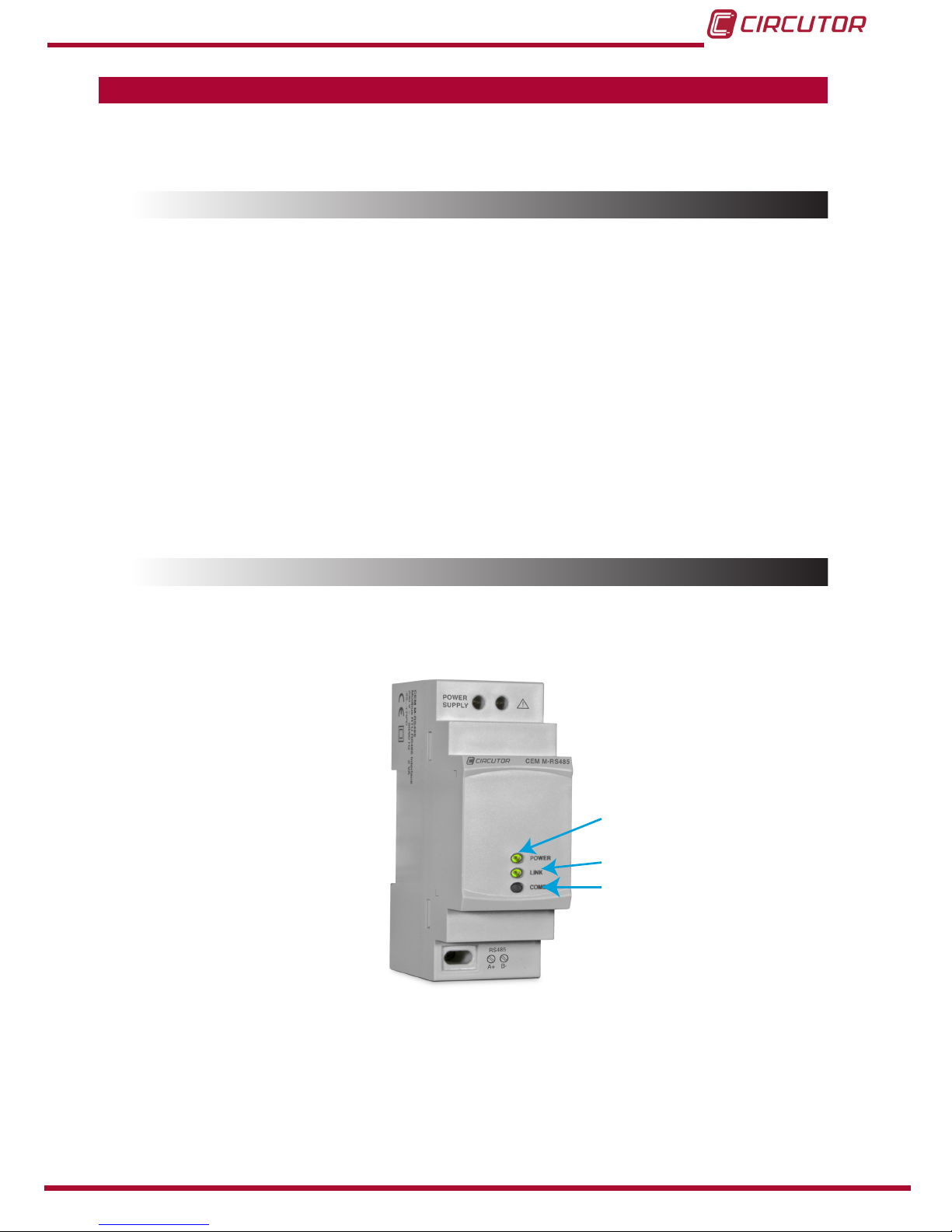
4.2.- LED INDICATORS
The unit has three indicator LEDs:
POWER
LINK
COMS
Figure 5:CEM M-RS485 indicator LEDs�
POWER LED: Indicates that the unit is connected to a power supply�
LINK LED: Indicates the status of the link with the CEM unit. (Table 3)
11
Instruction Manual
CEM M-RS485
Table 3:LINK LED, colour codes�
LINK LED
Colour Status
Flashing red Unit not linked
Steady green Unit linked
COMS LED: Flashes with each transmission made by the RS-485 port.
4.3.- OPTICAL COMMUNICATIONS PORT
The unit has an optical serial communications port on its right side, in accordance with the UNE
EN 62056-21:2003 standard, in order to communicate with other devices in the CEM family.
4.4- RS-485 COMMUNICATIONS
4�4�1�- MODBUS PROTOCOL
The MODBUS protocol is a communication standard in the industry that enables the network
connection of multiple units, where there is a master and multiple slaves. Within the MODBUS
protocol the CEM M-RS485 uses the RTU (Remote Terminal Unit) mode.
In RTU mode, message starts and ends are detected with silences of at least 3.5 characters,
and the 16-bit CRC error-detection method is used.
The MODBUS functions implemented in the unit are:
Functions 03 and 04. Reading logs.
Function 10. Writing multiple logs.
4�4�2�- READ COMMANDS
The CEM M-RS485 supports integer type read functions: 0x03 and 0x04.
The unit's Modbus variables are specied in Table 4.
Example: Reading of the unit's serial number with peripheral number 01.
We will send the following Modbus frame:
Address Function Initial log Log no� CRC
01 04 2710 0002 CRC
12
CEM M-RS485
Instruction Manual
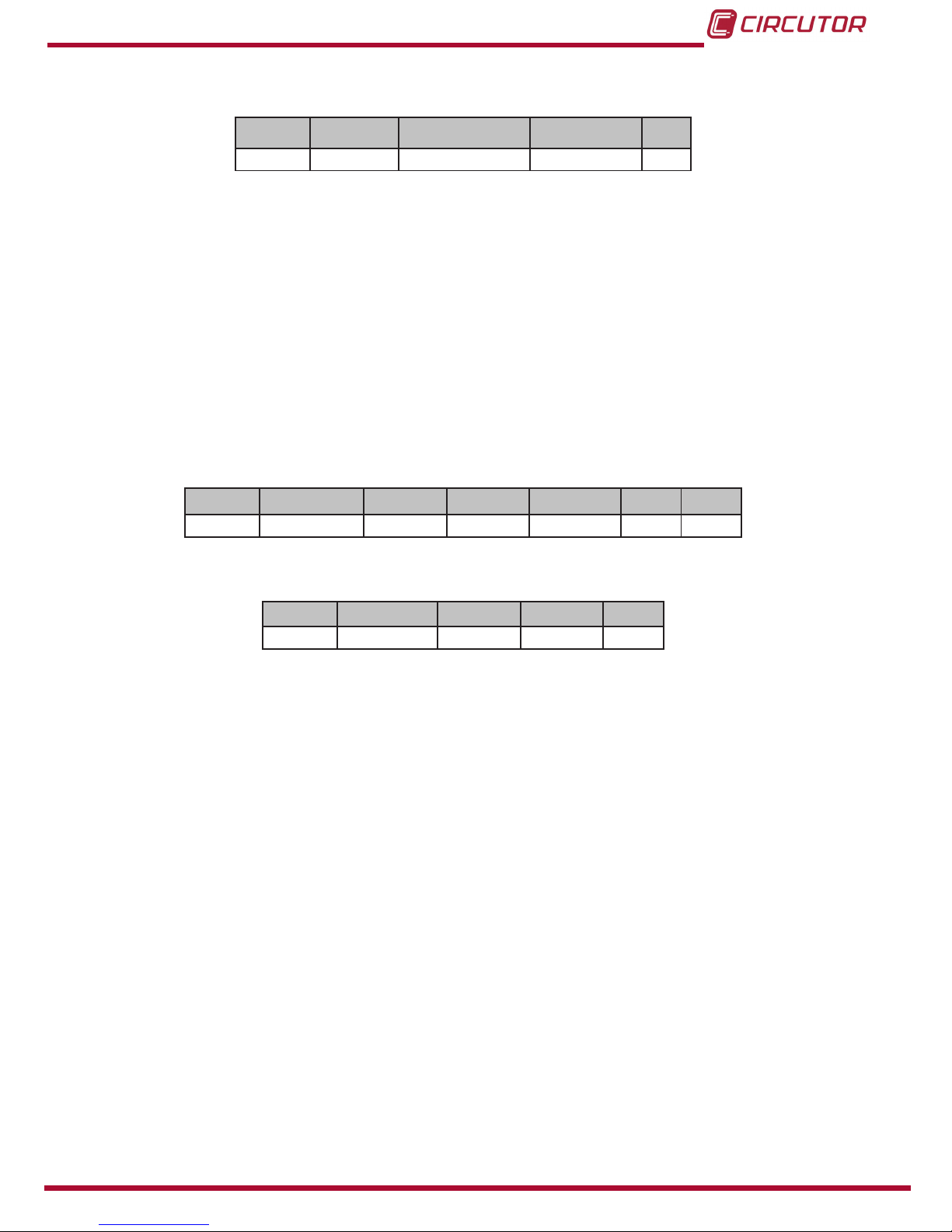
The unit will respond to us with the next frame:
Address Function No� of bytes Serial no� CRC
01 04 04 XXXX XXXX CRC
Note: The values are shown in hexadecimal.
The number of requested logs must be the same as the size of the variable requested.
It is possible to read several consecutive addresses, if the request meets the correct format.
4�4�3�- WRITE COMMANDS
The CEM M-RS485 supports integer type write functions: 0x01.
The unit's Modbus variables are specied in Table 4.
Example: Changing the Modbus address of peripheral 01 to the address 0x000A.
We will send the following Modbus frame:
Address Function Initial log Log no� No� bytes Data CRC
01 10 03E8 0001 02 000A CRC
The unit will respond to us with the next frame:
Address Function Initial log Log no� CRC
01 10 03E8 0001 CRC
Note: The values are shown in hexadecimal.
The number of logs to write must be the same as the size of the variable that is being
accessed.
It is possible to write several consecutive addresses, if the request meets the correct format.
13
Instruction Manual
CEM M-RS485
4�4�4�- VARIABLES MODBUS
All MODBUS map addresses are hexadecimal.
4�4�4�1�- Conguration variables
The Read and Write functions are implemented for these variables.
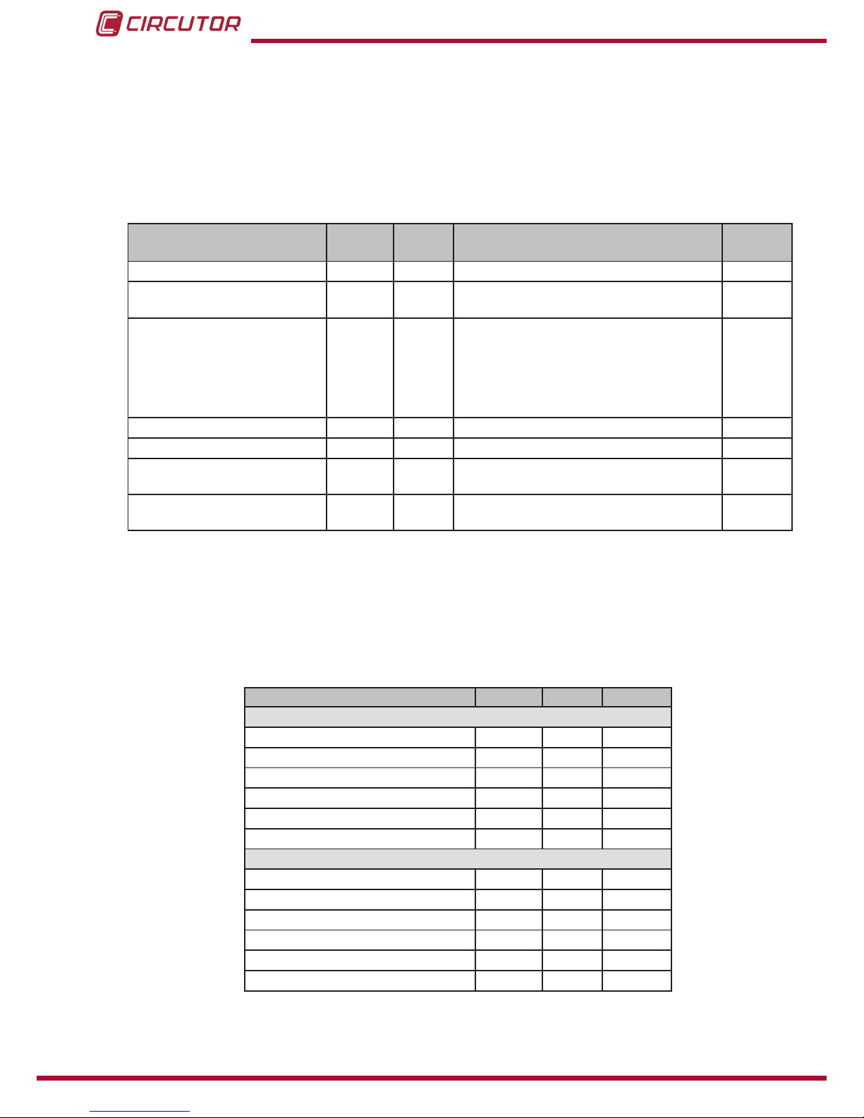
Table 4:Modbus conguration variables CEM M-RS485.
Description Address Size Valid data range Default
value
Modbus address 0x03E8 16 bits 1 ... 254 1
Transmission speed
(Baudrate) 0x03E9 16 bits 0: 9600, 1:19200, 2: 38400 0: 9600
Communications conguration 0x03EA 16 bits
0: 8N1 ( 8 bits - No parity -1 stop bit)
1: 8E1 ( 8 bits - Even parity -1 stop bit)
2: 8O1 ( 8 bits - Odd parity -1 stop bit)
3: 8N2 ( 8 bits - No parity -2 stop bit)
4: 8E2 ( 8 bits - Even parity -2 stop bit)
5: 8O2 ( 8 bits - Odd parity -2 stop bit)
0
Impulse output type 0x0080 16 bits 0: Active energy, 1: Reactive energy 0
Impulse output weight 0x0081 16 bits Wh/impulse 0 ... 99999 -
Cost per kWh 0x00B0 32 bits 0.0000 ... 9999.9999 with 4 decimal places
of resolution -
KgCO20x00B2 32 bits 0.0000 ... 9.0000 with 4 decimal places of
resolution -
Note: Some MODBUS variables may not be available depending on the CEM energy meter
coupled to the CEM M-RS485. See “4.4.4.7.- Available addresses by unit”
4�4�4�2�- Energy
The Read function is implemented for these variables.
Table 5: Modbus variables: Energy
Description Address Size Units
Total values
Imported active energy 0x0000 32 bits Wh
Exported active energy 0x0002 32 bits Wh
Q1 reactive energy 0x0004 32 bits varh
Q2 reactive energy 0x0006 32 bits varh
Q3 reactive energy 0x0008 32 bits varh
Q4 reactive energy 0x000A 32 bits varh
Partial values
Partial imported active energy 0x0030 32 bits Wh
Partial exported active energy 0x0032 32 bits Wh
Q1 partial reactive energy 0x0034 32 bits varh
Q2 partial reactive energy 0x0036 32 bits varh
Q3 partial reactive energy 0x0038 32 bits varh
Q4 partial reactive energy 0x003A 32 bits varh
Note: Some MODBUS variables may not be available depending on the CEM energy meter
coupled to the CEM M-RS485. See “4.4.4.7.- Available addresses by unit”
14
CEM M-RS485
Instruction Manual

4�4�4�3�- Operating time, cost and KgCO2 atmospheric emissions
The Read function is implemented for these variables.
Table 6: Modbus variables: Operating time, costs and KgCO2
Description Address Size Units
Cost of the partial consumption 0x00C0 32 bits -
KgCO2 atmospheric emissions of the partial consumption 0x00C2 32 bits -
Hours of partial operation 0x00C4 32 bits ( 1 decimal place)
Hours of total operation 0x00C6 32 bits ( 1 decimal place)
Note: Some MODBUS variables may not be available depending on the CEM energy meter
coupled to the CEM M-RS485. See “4.4.4.7.- Available addresses by unit”
4�4�4�4�- Instantaneous values
The Read function is implemented for these variables.
Table 7: Modbus variables: Instantaneous values�
Description Address Size Units
Phase 1 voltage 0x0732 32 bits V (1 primary decimal place)
Phase 2 voltage 0x0734 32 bits V (1 primary decimal place)
Phase 3 voltage 0x0736 32 bits V (1 primary decimal place)
Phase 1 current 0x0738 32 bits A (2 primary decimal places)
Phase 2 current 0x073A 32 bits A (2 primary decimal places)
Phase 3 current 0x073C 32 bits A (2 primary decimal places)
Phase 1 cos φ 0x073E 32 bits 2 decimal places
Phase 2 cos φ 0x0740 32 bits 2 decimal places
Phase 3 cos φ 0x0742 32 bits 2 decimal places
Phase 1 active power 0x0746 32 bits W
Phase 2 active power 0x0748 32 bits W
Phase 3 active power 0x074A 32 bits W
Total active power 0x074C 32 bits W
Phase 1 reactive power 0x074E 32 bits var
Phase 2 reactive power 0x0750 32 bits var
Phase 3 reactive power 0x0752 32 bits var
Total reactive power 0x0754 32 bits var
Phase 1 apparent power 0x0756 32 bits VA
Phase 2 apparent power 0x0758 32 bits VA
Phase 3 apparent power 0x075A 32 bits VA
Total apparent power 0x075C 32 bits VA
Note: Some MODBUS variables may not be available depending on the CEM energy meter
coupled to the CEM M-RS485. See “4.4.4.7.- Available addresses by unit”
15
Instruction Manual
CEM M-RS485

4�4�4�5�- Other parameters
The Read function is implemented for these variables.
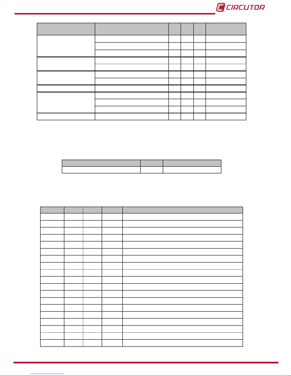
Table 8: Modbus variables: Other parameters�
Description Address Size Units
Energy meter model1) 0xF010 6x16 bits 12 bytes in ASCII format
Serial no 0x2710 32 bits -
Transformation ratios
Voltage primary 0x044C 32 bits V (1 decimal place)
Voltage secondary 0x044E 32 bits V (1 decimal place)
Current primary 0x0450 32 bits A (1 decimal place)
Current secondary 0x0452 32 bits A (1 decimal place)
Energy meter rmware version
Higher rmware version 0x0050 16 bits -
Lower rmware version 0x0051 16 bits -
Revised rmware version 0x0052 16 bits -
Communications module rmware version
Higher rmware version 0x0578 16 bits -
Lower rmware version 0x0579 16 bits -
Revised rmware version 0x057A 16 bits -
Note: Some MODBUS variables may not be available depending on the CEM energy meter
coupled to the CEM M-RS485. See “4.4.4.7.- Available addresses by unit”
(1) Energy meter model description table, Table 9�
Table 9: Energy meter model description table�
Options C10 C20 C30 bytes in ASCII
format
Connection mode 2 wires 2
4 wires 4
Accuracy
Class B active / Does not measure
reactive energy 10
Class B active / Class 2.0 reactive 12
Measurement voltage
1x230 E
1x127 B
3x127/220 ... 3x230/400 V U
3x127/220 V N
3x230/400 V Q
3x57/100 ... 3x230/400 V V
3x57/100 V L
3x63.5/110 V M
Current measurement
Shunt 10(60) A S4
Shunt 5(65) A S7
Direct 10(60)A D4
Direct 5(65)A D7
Transformer 5(10) A T5
Transformer 5(6) A T6
16
CEM M-RS485
Instruction Manual
Opciones C10 C20 C30 bytes en formato
ASCII
Frequency
50Hz A
60 Hz B
Automatic (50/60Hz) C
Communications Without communications 0
Side optical service port 1
Expansion Without inputs/outputs 0
Input/Output (Optocoupler) 1
Model Box for assembly on DIN rail E
Number of quadrants
2 quadrants 0
4 quadrants 1
Storage in both directions 2
Additional features No special features 0
4�4�4�6�- Partial energy reset
The 0x05 function is implemented for this variable.
Table 10: Modbus variables: Energy
Description Address Activation
Partial energy reset 0x0800 0xFF00
4�4�4�7�- Available addresses by unit
Table 11: Modbus variables: Available addresses by unit�
Address C10 C20 C30 Description
0x03E8 Modbus Address
0x03E9 Transmission speed
0x03EA Communications conguration
0x0080 Impulse output type
0x0081 Impulse output weight
0x00B0 Cost per kWh
0x00B2 KgCO2
0x0000 Imported active energy
0x0002 Exported active energy
0x0004 Q1 reactive energy
0x0006 Q2 reactive energy
0x0008 Q3 reactive energy
0x000A Q4 Reactive energy
0x0030 Partial imported active energy
0x0032 Partial exported active energy
0x0034 Q1 partial reactive energy
0x0036 Q2 partial reactive energy
0x0038 Q3 partial reactive energy
0x003A Q4 partial reactive energy
17
Instruction Manual
CEM M-RS485

Dirección C10 C20 C30 Descripción
0x00C0 Cost of the partial consumption
0x00C2 KgCO2 atmospheric emissions of the partial consumption
0x00C4 Partial operating time
0x00C6 Total operating time
0x0732 Phase 1 voltage
0x0734 Phase 2 voltage
0x0736 Phase 3 voltage
0x0738 Phase 1 current
0x073A Phase 2 current
0x073C Phase 3 current
0x073E Phase 1 cos φ
0x0740 Phase 2 cos φ
0x0742 Phase 3 cos φ
0x0746 Phase 1 active power
0x0748 Phase 2 active power
0x074A Phase 3 active power
0x074C Total active power
0x074E Phase 1 reactive power
0x0750 Phase 2 reactive power
0x0752 Phase 3 reactive power
0x0754 Total reactive power
0x0756 Phase 1 apparent power
0x0758 Phase 2 apparent power
0x075A Phase 3 apparent power
0x075C Total apparent power
0xF010 Energy meter model
0x2710 Serial no.
0x044C Voltage primary
0x044E Voltage secondary
0x0450 Current primary
0x0452 Current secondary
0x0050 Higher rmware version
0x0051 Lower rmware version
0x0052 Revised rmware version
18
CEM M-RS485
Instruction Manual
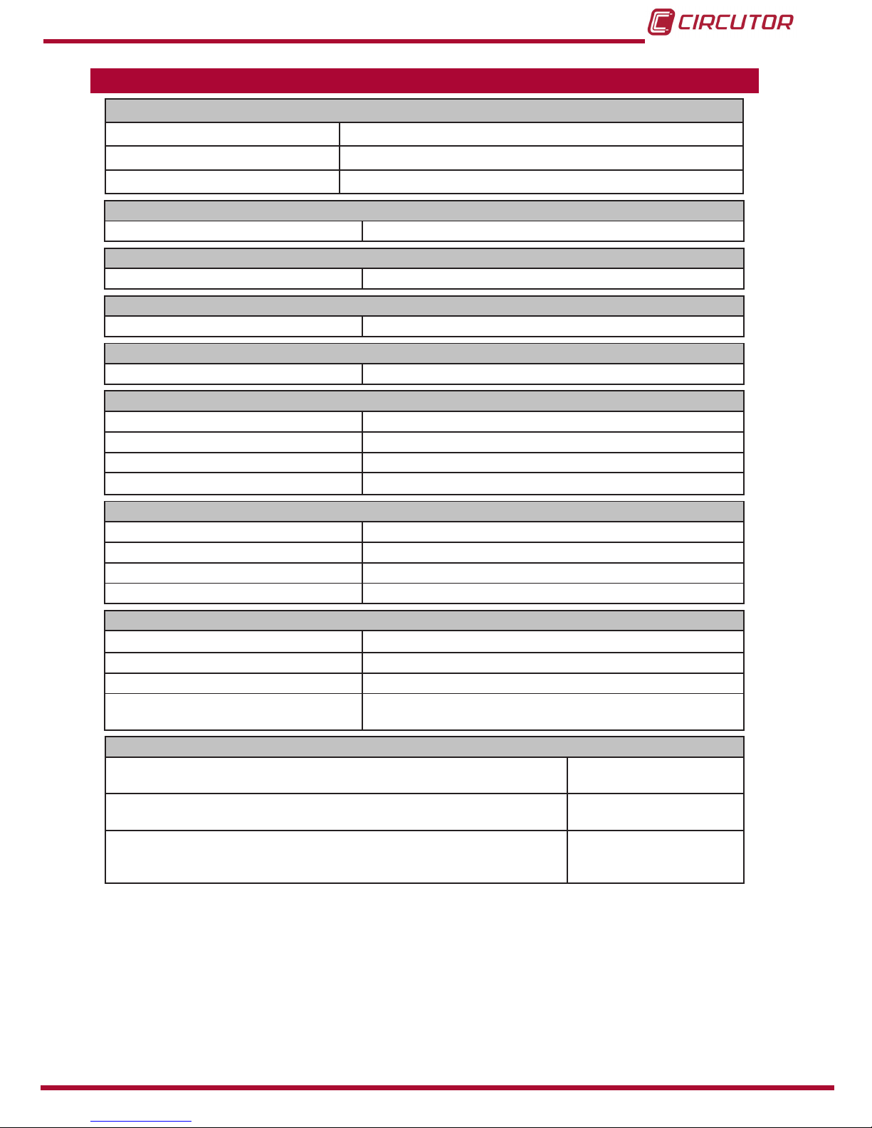
5�- TECHNICAL FEATURES
Power supply
Rated voltage 230 V~ ± 20%
Maximum power consumption 4 VA
Frequency 50/60 Hz with no differentiation
Insulation
AC voltage 4kV RMS 50Hz during 1 minute
Overimpulse
1�2/50ms 0Ωsource impedance 6 kV at 60º and 240º, with positive and negative polarization
Memory
Setup, events, load curve Non-volatile EEPROM memory
User interface
LED 3 LEDs (POWER - LINK - COMS)
RS-485 communication
Communications protocol Modbus
Baud rate 9600, 19200, 38400
Stop bits 1
Parity no parity
Environmental features
Operating temperature -25ºC... +70ºC
Storage temperature -35ºC... +80ºC
Relative humidity (non-condensing) 5 ... 95%
Maximum altitude 2,000 m
Mechanical features
Dimensions Figure 6
Enclosure ABS + V0 polycarbonate
Weight 115 gr
Protection degree IP 51 installed
IP 40 in the terminal area
Standards
Safety requirements for electrical units for measurement, control and
laboratory use� Part 1: General requirements� EN 61010-1: 2010
Electromagnetic compatibility (CEM)� Part 6-2: Generic standards�
Immunity for industrial environments� EN 61000-6-2: 2005
Electromagnetic compatibility (CEM)� Part 6-3: Generic standards�
Emission standard for residential, commercial and light industry envi-
ronments�
EN 61000-6-3: 2007
19
Instruction Manual
CEM M-RS485
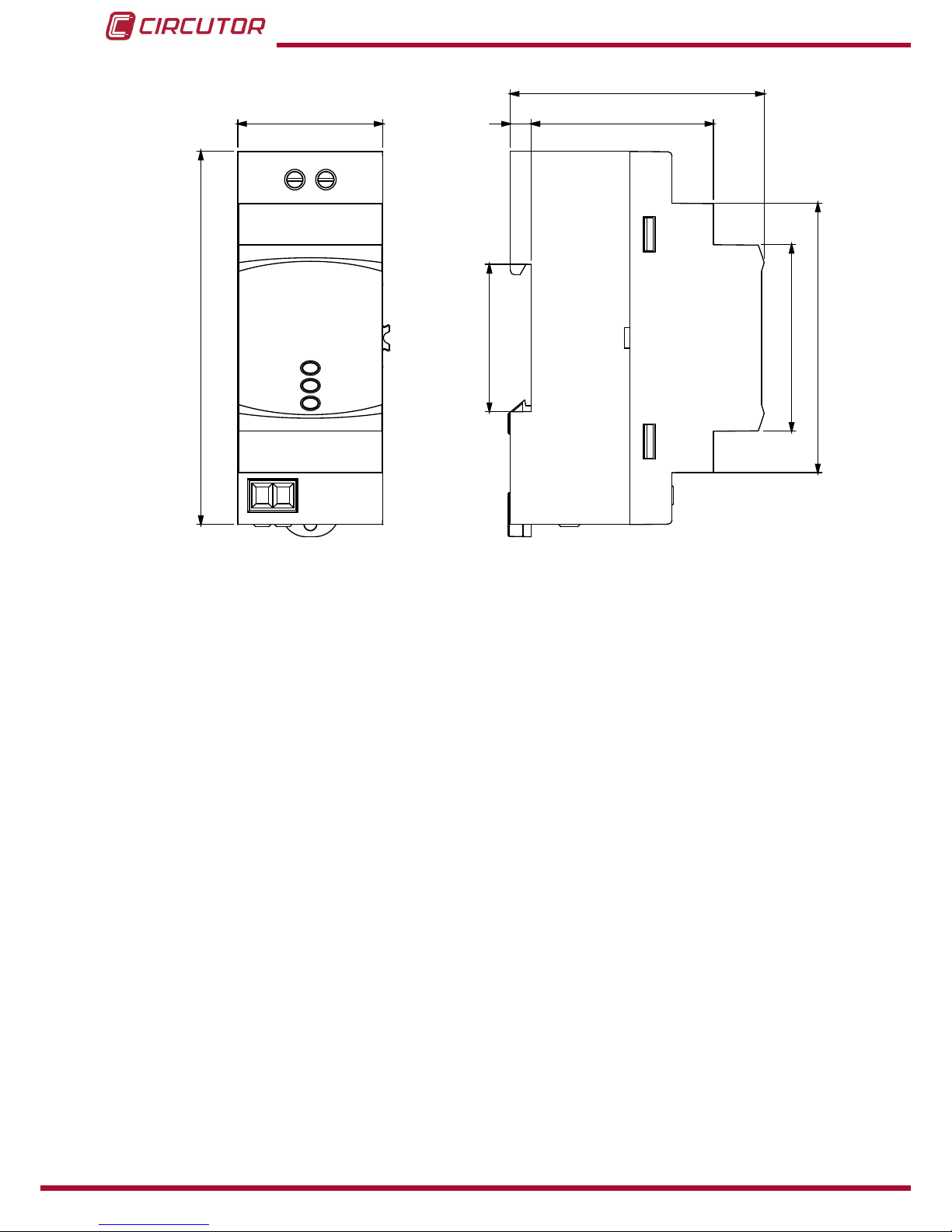
35
90
45
35.5
5 44
61
65
Figure 6: CEM M RS-485 dimensions�
20
CEM M-RS485
Instruction Manual
Table of contents
Other Circutor Recording Equipment manuals


