Befaco VCMC User manual

VCMC v1.1 - ASSEMBLY GUIDE
THANKS FOR CHOOSING ONE OF OUR KITS!
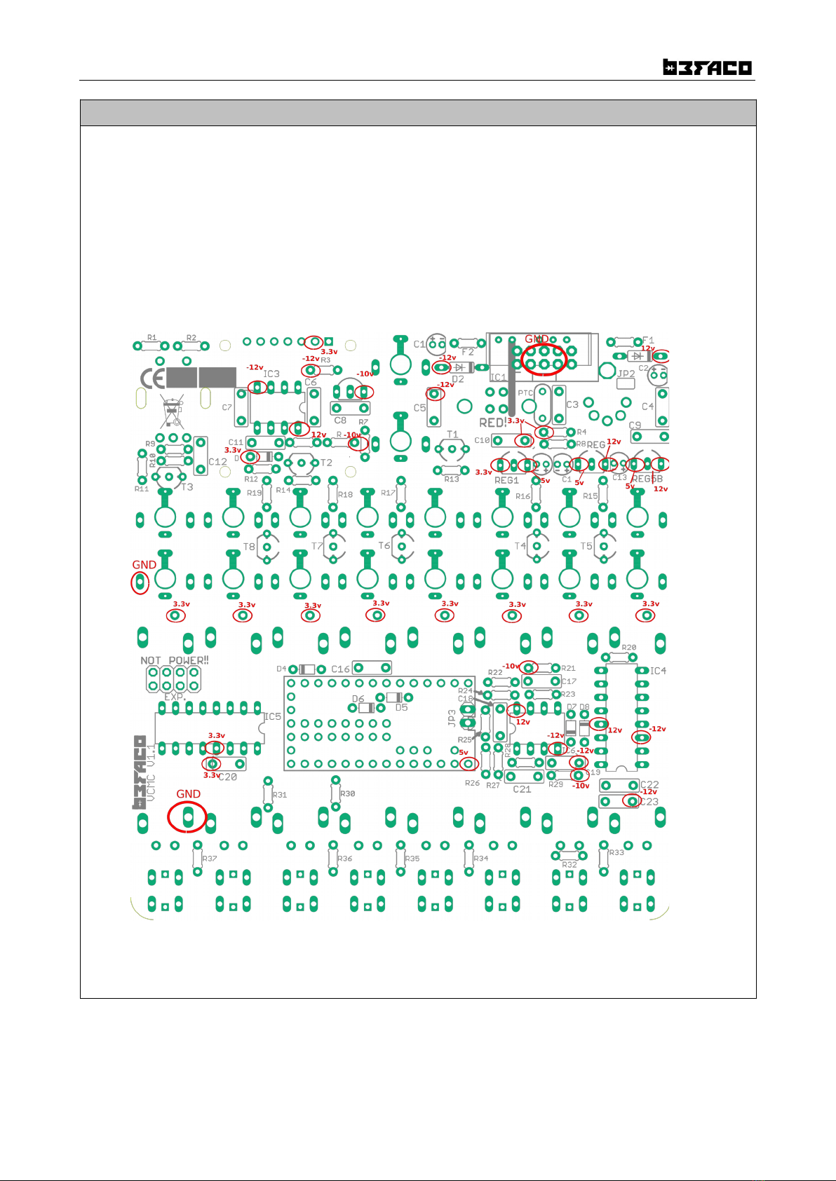
This assembly guide is a bi differen from he o her Befaco ones. We will be assembling sec ions, and es ing hem one
by one, so we will no keep building un il we make sure i is working nicely.
This will make our build a bi slower and careful, as his is quite a tricky build.
Some s eps are no obvious, so even if you're an experienced DIYer, please ake he ime o read he s eps horoughly
before s ar ing.
If his is your firs projec , please read his ar icle before you s ar assembling he ki :
www.befaco.org/how o/
OPEN AG A
RESISTORS
Q y Value Code Name on PCB
14 100k Brown, black, black, orange, brown R6, R7, R11, R13, R14, R15, R16, R17, R18, R19, R20,
R21, R26, R29
11 1k Brown, black, black, brown, brown R12, R25, R27, R30, R31, R32, R33, R34, R35, R36,
R37
4 10k Brown, black, black, red, brown R1, R2, R9, R10
5 33k Orange, orange, black, red, brown R5, R22, R23, R24, R28
2 56 ohm Green, blue, black, silver, brown R4, R8
1 2k2 Red, Red, black, brown, brown R3
DIODES
Solder he diodes observing their polarity. The black or whi e line on he diode mus ma ch wi h he whi e line on
he diode symbol on he PCB silkscreen.
Q y Value Name on PCB
2 1N5817 D1, D2
6 BAT85 D3, D4, D5, D6, D7, D8
FERRITES
Solder he wo ferri e beads by using a recycled diode leg passed hrough each ferri e and proceed as if i were a
resis or. Ferri e beads don' have polari y.
Q y Name on PCB+
2 F1, F2
1

VCMC v1.1 - ASSEMBLY GUIDE
IC SOCKETS
Firs we will place the sockets ( aking care o orien a e hem properly – he no ch on one end of he socke should
ma ch he silkscreen) and solder hem in o heir correc posi ions. Ge hem from ICs bag.
Q y Value Name on PCB
2 DIL8 IC3, IC6
2 DIL16 IC4, IC5
OPEN AG
CAPACITORS
Iden ifying capaci ors can be qui e ricky. Codes s a ed are indica ive, please ake a look a his guide for help
iden ifying capaci ors: h p://www.wikihow.com/Read-a-Capaci or
Q y Value Code Name on PCB
15 100n 104 C3, C4, C5, C6, C7, C8, C9, C10, C12, C16, C18, C19, C20, C22, C23
5 10uF (POLARIZED!) 10uF C1, C2, C13, C14, C15
2 1nF 102 C11, C21
1 22p 220 C17
REGULATORS
Make sure i is posi ioned correc ly wi h reference o he silkscreen ou line on he PCB
Q y Code Name on PCB
2 78L05 REG5A, REG5B
1 78L33 REG1
1 LM4040 REG-10
POWER CONNECTOR
Solder he power connec or a “POWER”, ensuring he posi ion is correc : i mus be placed over he silkscreen marking
wi h he pins facing he edge of he PCB.
The rest of the components in this bag will be mounted later in the process.
2

VCMC v1.1 - ASSEMBLY GUIDE
TROU LESHOOTING
A his poin we will perform a smoke es and check ha power arrives o every relevan spo in he board.
This is very impor an , as es ing all his once mechanical componen s are soldered will be hard.
Connec he module o a power supply and follow nex page diagram o measure ALL marked vol ages.
If your power supply behaves funny or one of he regula ors ge ho , unplug he module immedia ely. Possible errors:
- One of he regula ors is reversed
- Reversed Diode.
- Reversed elec roly ic capaci or.
- Maybe you have a bridge somewhere.
Use one of he marked GND spo s and measure one by one he vol ages
If all vol ages are good (keep in mind hey migh change a bi due o olerances and your power supply) proceed wi h
he res of he build.
If you are facing issues, please follow our basic roubleshoo ing guide:
https://www.befaco.org/en/trubleshooting-questions/
3

VCMC v1.1 - ASSEMBLY GUIDE
OPEN TEENSY AG
PREPARING TEENSY
This par on he build is cri ical. We will be soldering pins o our Teensy board, being
some of hem SMD and EXTREMELY delica e. So please follow ins ruc ions and be ex ra-
careful.
Scan his QR o check a video on our you ube channel soldering he pins.
We will prepare female pin headers ha will be soldered o he board, and male pin
headers ha will be soldered in Teensy board.
We will ry firs o place hem all, make sure hey fi s ress-free and hen solder.
Firs of all we will solder SMD pin headers o backside of Teensy board. Make sure ha
you work on a clear area. Try o fix Teensy board on a way ha i will no move and make work smoo her. For
example, you can use ICVs foam o s ick i and make i s able.
Solder he 1x2 SMD pins as pic ured, ha will be soldered a USB pads. Wi h ex reme care solder hem o he usb
pins, making sure hey are s raigh . Soldered pins (shor es ones) mus be facing in o he PCB, so he connec ing pins
(longes ones) will be flush wi h he PCB side.
Cu he SMD connec or so i is same size as he pads In he bo om of he board (2x7). Proceed o solder i making
sure hey are cen ered in he pads and s raigh .
WARNING: Pads in Teensy board are very delica e, rea hem gen ly, if soldering is becoming hard, le i res and ry
la er.
Make sure you do no bridge he USB pads wi h he pads close by. If soldering is ge ing hard, please s op and le i
res . SMD Pads migh be damaged.
Place male pin headers a Teensy holes, bu do no solder hem. We will be placing hem on he board firs o make
sure i fi s properly. Bu only af er nex s ep.
4

VCMC v1.1 - ASSEMBLY GUIDE
Now we will proceed o place female pin headers in he pcb:
FEMALE PIN HEADERS
Place all pins on he PCB o fi Teensy size, a componen s side, but do not solder them.
Q y Size Place on PCB
2 1X14 Long sides
1 1X5 Shor sides
1 1X2 Ma ching SMD pins in Teensy
1 2X7 Cen ral posi ion
Place Teensy board on he female pins. Do his gently, SMD pins are qui e delica e and make sure all pins are firmly
connec ed and fla agains he board.
Once all pins are in place, proceed to solder them all.
Now we will moun he spacers and he OLED Screen which are loca ed on he mechanical side of
he PCB.
SPACERS
Secure he 7 mm. spacers on o he PCB in he upper side of he board, o fi he OLED screen. Place hem a
mechanical componen s side.
OLED SCREEN
Cu he 14p socke in half. Then place one of he halves In he 7 holes for he OLED. Making sure i is no ge ing ou
of he board. Bu do not solder it.
Cu OLED pins ~2mm so i will be fla and paralel o he PCB once a ached o he socke . Then we will place he OLED
o his socke , screw i o he spacers and proceed o solder the socket.
5

VCMC v1.1 - ASSEMBLY GUIDE
TROU LESHOOTING
Plug he module and make sure ha he screen is showing Befaco splash screen, hen module main screen appears.
The bars will be a bi crazy, i is normal! If screen does no ligh up, hen some hing is fishy wi h your soldering ei her
in he Teensy or he OLED.
If it lights up, remove Teensy and OLED gently and continue with the build.
TRANSISTORS
Make sure i is posi ioned correc ly wi h reference o he silkscreen ou line on he PCB
Q y Code Name on PCB
8 2n3904 T1, T2, T3, T4, T5, T6, T7, T8
MALE PIN HEADERS
Place he 2x4 pin headers on EXP following he silkscreen.
ICs
Place ICs in heir socke s. Take care of polari y, no ch or do mark orien a ion.
Q y Value Name on PCB
2 DG408 IC4, IC5
2 TL072 IC3, IC6
Now we will proceed o moun he jacks, MIDI connec or, bu on and encoder. This par of he assembly is CRITICAL.
Please ake your ime and read he following ins ruc ions carefully.
These componen s mus NOT be soldered un il hey are placed on he PCB and fully a ached o he fron panel.
Af er solder every componen of his bag, be sure ha he legs are cu shor enough in order o no ouch he
mechanical componen s ha we will place and solder now.
OPEN MECHANICAL COMPONENTS AG
SPACERS
Secure he 11 mm. spacers on o he PCB. These are he ones ha go close o he bu ons, place hem facing
mechanical components as hey will be screwed o he panel la er on.
US CONNECTOR
Place USB connec or bu don't solder it yet.
6

VCMC v1.1 - ASSEMBLY GUIDE
MINIJACK
Place he mini-jacks on he PCB ensuring hey are on he side wi h he silkscreen bu don't solder them.
A his poin we will place and screw he OLED in place. So we can es he module a bi fur her.
Place front panel and screw he nu s (one in each corner should be enough). Screw also he wo spacers using wo
M2 screws.
Solder Minijacks and US connector.
TROU LESHOOTING
A his poin we are ready o es CV and Ga e inpu s on he module. Pu Teensy back in place gen ly, hen power he
module on .
Plug some CV sources o he inpu s. You should see relevan columns moving wi h he CV. Warning: Fader columns
will be moving crazy, pay a en ion o CV ones only.
Connec he module o your compu er via USB. I should be au oma ically recognized and VCMC Midi con roller added
o your sys em. As a double check, you can see if MIDI messages are arriving.
If every hing is fine, remove the panel and keep wi h he assembly.
FADERS
Before placing he faders make sure your soldering is idy and regular.
Place he faders on he PCB where he silkscreen indica es, make sure hey are fla and proceed o solder he hree
pins. Do not solder location lugs yet, wai ill he end of he build when every hing is working fine.
TIP: Make sure no legs are ben and all are passing hru heir holes. A mis ake here will cause ex reme suffering
la er.
If you power he module back in you should be able o check ha fader columns move accordingly.
ENCODER
Place he encoder on he PCB where he silkscreen indica es. Leave a nu and wo washers under he board bu
don't solder it yet.
UTTONS
Place he push bu ons on he PCB where he silkscreen indica es, aking care of he orien a ion. Fla side mus ma ch
he silkscreen, don't solder them yet.
TIP: Make sure all legs passed hru holes, fixing his la er is ra her painful.
FRONT PANEL
Place he plastic window in o fron panel OLED hole, from he back side of he panel. Use some ho glue, ape or any
me hod of your choice. Remember o remove he pro ec ion plas ic from i .
A ach he front panel adjus ing he par s one by one if necessary un il hey fi . You can use some masking ape o
hold he bu ons in place before soldering.
To finish:
- Secure he par s o he panel in his order: A) Mini-jacks B) Screws for the spacers C) Encoder
- Ensuring all of he above par s are flush wi h he panel hen you can finally solder he encoder.
- Nex , we will be soldering he push bu ons. Press hem o make sure hey are fla , if you are no using
masking ape. Then solder hem.
- Solder he faders hree con ac pins, making sure hey are s raigh and parallel o he board. Do no solder
he four loca ing pads. Wai un il he module is working and fully es ed.
7

VCMC v1.1 - ASSEMBLY GUIDE
FINAL TROU LESHOOTING
Now is he ime o plug your module o check ha every hing is working as expec ed.
Module should power on and screen should show he boo ing sequence. If i does no boo , and/or you no ice some
weird behavior or hea ing, disconnec he module and perform fur her roubleshoo ing. Keep in mind when was he
las successful es , so check wha you did from here.
If module is boo ing, move faders and plug some CV sources o he inpu s o check if you can see feedback in he
screen. Also, pressing bu ons should make he Leds blink.
A his poin aking a look o our User manual migh help o unders and if every hing is fine.
Af er he basic es ings are successful, you can proceed o solder loca ion legs of he faders.
MIDI CONNECTOR
Place he MIDI connec or hru he hole. Placing he nu jus before connec ing i o he board.
Fas en he nu so he connec or is s raigh and flush agains he PCB. Then solder PINS 4 and 5 (The wo a he
sides of cen ral one).
Soldering his a he very end is CRITICAL, as panel is really hard o remove once his connec or is soldered.
Make sure every hing works fine before doing so.
CALI RATION
We will perform now a fac ory callibra ion. This procedure need o be done wi h a very precise vol age source. We
sugges o measure wi h a hree digi s mu ime er.
In order o ge in o calibra ion mode, press he encoder for more han hree seconds, his will ge you in o general
se ings menu.
Scroll o credi s, when splash screen appears, keep encoder pressed in order o make Global calibra ion op ion
available.
When splash screen disappears, scroll down o access global cal.
- Calibrating Faders.
Move all faders o maximum posi ion un il all values s abilize. Then move all of hem o zero. Press end o s ore he
values
- Calibrating Cvs.
We will be en ering o a wo poin s calibra ion screen. You will be promp ed o send 1v and 4 vol s, so hey will be
s ored and correc ing any even ual offse and non lineari y in your CV source.
Make sure your CV source is precise enough!
- Calibrating Aux.
We will be en ering o a wo poin s calibra ion screen. You will be promp ed o send 1v and 4 vol s, so hey will be
s ored and correc ing any even ual offse and non lineari y in your CV source.
Make sure your CV source is precise enough!
ENJOY YOUR NEW EFACO MODULE!
8
Other manuals for VCMC
4
Other Befaco Recording Equipment manuals

Befaco
Befaco MIDI THING User manual

Befaco
Befaco VCMC User manual

Befaco
Befaco VCMC User manual

Befaco
Befaco STAmp 1U User manual

Befaco
Befaco AC/DC User manual

Befaco
Befaco PONY VCO User manual

Befaco
Befaco ST AMP User manual

Befaco
Befaco VCMC 1.1 User manual

Befaco
Befaco FX BOY User manual

Befaco
Befaco AC/DC User manual