Ganz CDR-16T User manual

CBC (EUROPE) LIMITED
Digital RECORDER CDR-16T
(1ST EDITION)
OPERATION MANUAL

General Considerations
Power Supply
Verify your unit has the correct voltage specifications for your power source prior to applying
power by reading the voltage range on the rear panel near the AC connector. The CDR-16T
normally operates on 100-240VAC ±10%; 50/60Hz. Do not attempt to operate these units using
a source having different specifications.
Location
Avoid using the CDR-16T in areas having high humidity, high temperature, or excessive dust.
Adequate ventilation is also required for optimum performance. As a result of this consideration,
ensure no other equipment is located or installed closer than 5cm to any unit.
Fuse
If a fuse blows, replace it with one the same rating as indicated below with unit power switched
off. Note only qualified personnel should perform fuse replacement. If fuse blows frequently, turn
power off and contact your supplier.
Fuse used in CDR-16T is as below:
250V, T4.0A, slow blow type (100-240VAC)
Desk or Tabletop Use
Unit baseplates are fitted at the factory with rubber feet to allow immediate usage as a desk or
tabletop unit.
Rack Mounting
The CDR-16T can be mounted to EIA standard rack units. When rack mounting a unit, remove
the rubber feet and use the accessory rack mount brackets (rack ears).

Upon Receipt
Unpacking
The CDR-16T is fully inspected and adjusted prior to shipment and can be operated immediately
upon completing all required connections and operational settings.
Check your received items against the packing list below.
ITEM
QTY
REMARKS
CDR-16T 136GB, 72GB or 180GB internal hard drive model
depending on purchase
SCSI Termination
Connector 1For connection to SCSI connector if no external
drives connected. (Or to last SCSI connector of
last drive if external drives configured.)
AC Cord 1
Rack Mount Brackets 1 pr. EIA standard type
Operation Manual 1
Check
Check to ensure no damage has occurred during shipment. If damage has occurred, or items
are missing, inform your supplier immediately.

TABLE OF CONTENTS
1. Prior to Starting ....................................................................................................................1
1-1. Welcome........................................................................................................................1
1-2. About the CDR-16T......................................................................................................1
1-3. About This Manual........................................................................................................2
2. Panel Descriptions...............................................................................................................3
2-1. Front Panel....................................................................................................................3
2-2. Rear Panel.....................................................................................................................6
3. Setup and Connection.........................................................................................................8
3-1. Connection.....................................................................................................................8
3-1-1. Basic Connection..................................................................................................8
3-1-2. Computer / Remote Control Connection...........................................................9
3-1-3. External Hard Drive Setup.................................................................................10
3-2. Connector Information...............................................................................................11
3-2-1. RS-232C Connector............................................................................................11
3-2-2. Remote Connector..............................................................................................12
3-2-3. Alarm Connector..................................................................................................14
3-2-4. SCSI Connector...................................................................................................16
4. Basic Operation..................................................................................................................17
4-1. Power ON / OFF.........................................................................................................17
4-2. Resetting to Factory Defaults...................................................................................18
4-3. Screen Display............................................................................................................18
4-3-1. Full Screen...........................................................................................................18
4-3-2. Split Screen..........................................................................................................22
4-3-3. Date / Time Messages........................................................................................23
4-4. Full Screen Display Operations................................................................................24
4-4-1. Zoom.....................................................................................................................25
4-4-2. Auto Sequence....................................................................................................26
4-5. Split Screen Display Operations ..............................................................................27
4-5-1. Patterns.................................................................................................................28
4-5-2. Channel Groups..................................................................................................29
4-5-3. Changing Main Position Camera......................................................................31
4-5-4. Channel Group Auto Sequence........................................................................33
4-6. Record / Playback......................................................................................................36

4-6-1. Manual Record....................................................................................................36
4-6-2. Auto Record.........................................................................................................36
4-6-3. Playback and Search..........................................................................................37
5. Using Menus.......................................................................................................................38
5-1. Accessing MAIN Menu..............................................................................................38
5-2. Accessing Function Menus.......................................................................................41
6. MAIN Menu Settings.........................................................................................................42
6-1. Protect..........................................................................................................................44
6-2. Split Position................................................................................................................46
6-3. Record Programming.................................................................................................48
6-3-1. Continuous Record.............................................................................................49
6-3-2. Pre Alarm Record................................................................................................52
6-3-3. One Shot Record.................................................................................................54
6-3-4. Regarding Record Channel Setting .................................................................55
6-3-5. Regarding Timelapse / Update Mode Setting.................................................58
6-3-6. Regarding Trigger Setting..................................................................................62
6-3-7. Regarding Continuous Record Setting............................................................63
6-4. Timer Program............................................................................................................66
6-5. Auto Seq Time.............................................................................................................69
6-6. Title Settings................................................................................................................70
6-7. Date / Time Settings...................................................................................................71
6-8. Display Mode...............................................................................................................72
6-9. Alarms..........................................................................................................................76
6-9-1. Alarm Settings......................................................................................................76
6-9-2. Regarding Alarm Display...................................................................................78
6-10. HDD............................................................................................................................80
6-10-1. Assign HDD Use...............................................................................................81
6-10-2. Format HDD.......................................................................................................83
6-10-3. Clear Event........................................................................................................85
6-11. Other Settings...........................................................................................................87
6-12. System Information..................................................................................................88
7. Function Menu Settings....................................................................................................89
7-1. Date / Time Search.....................................................................................................91
7-2. Index List Search........................................................................................................93
7-3. HDD Information.........................................................................................................96
7-3-1. All Connected HDD.............................................................................................96

7-3-2. Specified HDD.....................................................................................................98
7-4 Power ON / OFF Log..................................................................................................99
8. Sensor Operation............................................................................................................101
8-1. Sensor Menu............................................................................................................101
8-1-2. Sensitivity Settings...........................................................................................102
9. DVD Option......................................................................................................................105
9-1. DVD Option Information.........................................................................................105
9-2. DVD Menu screen...................................................................................................106
9-2-1. Assigning DVD Use.........................................................................................107
9-3. Formatting DVD.......................................................................................................109
9-4. Clearing Events.........................................................................................................111
9-5. User Select Backup..................................................................................................112
9-5-1. To Make User Backup ......................................................................................114
9-5-2. Changing Disks During User Backup.............................................................117
9-6. Auto Backup..............................................................................................................118
9-6-1. Auto Backup ON/OFF.......................................................................................118
9-6-2. Auto Backup / Program Relationship.............................................................119
9-6-3. Changing Auto Backup Disk...........................................................................121
9-6-4. Auto-backup Memory Function......................................................................123
9-6-5. Auto Backup Interrupt......................................................................................125
9-7. Timer Auto Backup..................................................................................................126
9-7-1. Auto Backup Using Timer Program...............................................................126
9-7-2. Regarding Timer Auto Backup.......................................................................127
9-7-3. Changing Disk During Timer Auto Backup...................................................128
9-7-4. Record During Timer Auto Backup................................................................129
9-8. Viewing Backup Data..............................................................................................130
9-9. DVD Index Search...................................................................................................131
9-10. DVD Drive Information..........................................................................................133
9-11. Other Settings........................................................................................................134
10. If Problems Occur.........................................................................................................135
11. Specifications & Dimensions.......................................................................................137
11-1. Unit Specifications.................................................................................................137
10-2. External Dimensions.............................................................................................139

1
1. Prior to Starting
1-1. Welcome
Congratulations! By purchasing a CDR-16T you have entered the world of CBC and its many
innovative products. Thank you for your patronage and we hope you will turn to CBC products
again and again to satisfy your video and audio production needs. Whatever your needs, talk to
your CBC representative. We will do our best to be of continuing service to you.
1-2. About the CDR-16T
The CDR-16T combines the best features of digital recorders and multiplexer products in one
compact package. Triplex operation capability, high quality performance and fast response
make it excellent for use at banks, casinos, stores, factories, theaters, museums, governmental
institutes, airports or other institutions with ongoing surveillance / observation needs. Units are
available shipped with one of three different capacity internal hard drives; (36GB), (72GB) or
(180GB).
Up to 16 composite video camera signals can be input and frame-switch recorded into its hard
disk drive memory. It also has a built-in frame synchronizer with 2-frame wide window correction
to assure even asynchronous signals can be fully utilized. Each recorded camera scene can be
retrieved and displayed independently (full screen), or multiple camera channels can be viewed
simultaneously on the same monitor as a split display. Motion adaptive JPEG compression
record, selectable compression rates (record quality settings), alarm record real time (NTSC 60,
PAL 50 fields / sec.) and multiple record mode settings.
All alarm events, including power ON/OFF, can be time stamped with year, month, date, hour,
minute and second of occurrence. Each event recorded can also be nonlinearly accessed at any
time for review and observation. Picture quality remains high from first playback to last; no
deterioration occurs no matter how many times the same scene is replayed. There is also no
picture disturbance during shuttle operation and slow motion playback is extremely smooth.
Features
ØNo PC based technology. Operate as stand alone. Designed to insure long term reliability.
ØAccepts any asynchronous or synchronous composite color or B/W signal input.
(Loopthrough output of each input is possible.)
ØInput video recorded to internal hard disk drive.
ØOptional DVD drive to back up critically needed security recordings.
ØNonlinear recording means nearly instantaneous access to needed video.
ØConfigure multiple external hard drives to increase record capacity.
ØSpecify drives as ‘playback only’or ‘record / playback’use.
ØNoise free motion during shuttle, noise free stills during jog.
ØSmooth slow motion playback, no picture deterioration after repeated playbacks.
Ø3000 alarm index memory for each configured HDD. Year, month, day, hour, minute, and
second of occurrence memorized for each alarm.
(Continued following page.)

2
ØRecord realtime or using one of the record interval (update or timelapse) settings.
ØFull screen and split display auto camera switchover (dwell time) selectable as 1-30 seconds.
ØTriplex operation capable; recorded signals can be retrieved and viewed, or camera inputs
directly observed full size or split display mode, on a single monitor while still recording.
ØBuilt-in character generator allows title ID line of up to 16 alphanumeric characters to be
displayed for each camera input depending on display mode.
ØRS-232C interface for computer command control of most operational functions.
1-3. About This Manual
This manual is intended to help the user easily operate the CDR-16T and make full use of its
functions during operations. Before connecting or operating your unit, read this operation
manual thoroughly to ensure you understand the product. After reading, it is important to keep
this manual in a safe place and available for reference.

3
2. Panel Descriptions
2-1. Front Panel
Where:
① Power Switch
Switch used to turn unit power ON / OFF. Power is ON when power indicator ②is lit green.
② Indicators
POWER indicator lights green whenever power switch is set to ON and power is applied to the
unit.
DRIVE 1 indicator lights green whenever drive 1 (hard disk) is accessed.
DRIVE 2 indicator lights green whenever drive 2 (optional DVD) is accessed.
FAN ALM indicator lights red whenever rear panel fan fails. (If this happens, turn off your unit
immediately and contact your nearest CBC representative.)
③ AUTO /ALARM RESET
AUTO (button lit)
Used to initiate auto sequence switching (full or split screen) of camera channels when in LIVE
mode. (See sec. ‘4-4-2. Auto Sequence’and ‘4-5-4. Channel Group Auto Sequence’.)
ALARM RESET (button flashing)
Button goes to flashing when an alarm signal is input or a video signal is lost.Pushingthis button
at that time (alarm condition) usually resets the unit to normal operation.(Current alarm
terminated, awaiting next alarm input.)
Alarm cannot be reset, however, if alarm signal input is still low level condition and setting in
related alarm menu is to LEVEL. (See sec. ‘6-9-1. Alarm Settings’.)
(Continued following page.)
CDR-16TDigitalRecorder
FWDREV
CDR-16TDigitalRecorder
FWDREV
CDR-16TDigitalRecorder
FWDREV
CDR-16TDigitalRecorder
FWDREV
POWERZOOMCH STOPJOG/SHTL
CONTROLPLAY*LV/P B
MENU
MONITOR
S PLIT
RES ET
ALARMBC DA
CAMERASE LECT
2345 678AUTO1 9 10 11 12 13 151 4 16
ENTER
DRIVE 1
FANALM
DRIVE 2
FE
FU NC
‚n‚e‚e
‚n‚m
POWER
REC
POWERZOOMCH STOPJOG/SHTL
CONTROLPLAY*LV/P B
MENU
MONITOR
S PLIT
RES ET
ALARMBC DA
CAMERASE LECT
2345 678AUTO1 9 10 11 12 13 151 4 16
ENTER
DRIVE 1
FANALM
DRIVE 2
FE
FU NC
‚n‚e‚e
‚n‚m
POWER
REC
POWERZOOMCH STOPJOG/SHTL
CONTROLPLAY*LV/P B
MENU
MONITOR
S PLIT
RES ET
ALARMBC DA
CAMERASE LECT
2345 678AUTO1 9 10 11 12 13 151 4 16
ENTER
DRIVE 1
FANALM
DRIVE 2
FE
FU NC
‚n‚e‚e
‚n‚m
POWER
REC
POWERZOOMCH STOPJOG/SHTL
CONTROLPLAY*LV/P B
MENU
MONITOR
S PLIT
RES ET
ALARMBC DA
CAMERASE LECT
2345 678AUTO1 9 10 11 12 13 151 4 16
ENTER
DRIVE 1
FANALM
DRIVE 2
FE
FU NC
‚n‚e‚e
‚n‚m
POWER
REC
②③④⑦⑧⑨⑩ ⑪⑫⑬ ⑭ ⑮⑯
①⑤⑥⑰
⑱⑲⑳

4
④ CAMERA SELECT 1−16
Used to select any single camera for full screen display or to assign cameras to positions in split
displays.(See sec. ‘6-2. Split Position’.)
⑤ CHANNEL GROUP SELECT A−F
Used to select which channel group of a split display pattern is used when viewing camera video
in SPLIT mode. Same type pattern channel groups (See sec. ‘4-5-2. Channel Groups’.) can be
auto sequenced using ③. Note that display pattern setting at ⑥is needed and ⑦must be
flashing (split select mode) for setting here to be valid.
⑥
Used to select which split display pattern is used when viewing camera video in SPLIT mode.
Note that channel group setting at ⑤is needed and ⑦must be flashing (split select mode) for
setting here to be valid.
⑦ SPLIT button
Sets split display select mode (button flashing) ON. After entering split display select mode (this
button flashing), settings ⑥(split pattern) and ⑤(channel group) can be selected. Split display
select mode ends (this button stops flashing) when selection is made at ⑤or ⑥or after approx.
5 sec. have elapsed. (See sec. ‘4-5. Split Screen Display Operations’.)
⑧ CH (channel) button
Used to select camera displayed at main position in split pattern when in SPLIT mode. (See sec.
‘4-5-3. Changing Main Position Camera’.)
⑨ ZOOM button
Used for x2 zoom in of selected area in camera scene when operating in full screen display
mode. (See sec. ‘4-4-1. Zoom’.) Cannot be used in SPLIT mode.
⑩ LV (live) / PB (playback) button
Used to select live view display of camera video or playback of previously recorded video.
Button will be lit when in LIVE view mode.
⑪ MENU button and indicators
Used to select normal or menu mode operation of unit. Top indicator will be lit when CDR-16T is
operating normally, bottom indicator is lit when in MENU mode. (See sec. ‘5. Using Menus’.)
Note that MENU mode select switch is recessed into the front panel. Switch should be carefully
pushed with a non-metallic probe tool to change between MENU / normal operation mode.
⑫ FUNC button
Used to access FUNCTION menu. (See sec.’5-2. Accessing Function Menus’.)
⑬ REC / ↓button
Used to initiate REC operation when unit is in OPERATION mode.
Or
Used to change between menu selections when in MENU mode.
⑭ STOP / ↑button
Used to STOP record operation when unit is in OPERATIONmode.
Or
Used to change between menu selections when in MENU mode.
(Continued following page.)

5
⑮ PLAY / →button
Used to initiate PLAY (playback) operation when unit is in OPERATION mode.
Or
Used to change menu setting data when in MENU mode.
⑯ JOG / SHTL / ENTER button
Used to stop PLAY (playback) operation and place recorder in JOG mode. Dial ⑰used to
perform jog search.
Or
Used to initiate JOG / SHTL mode operation. Dial ⑰used to perform jog and shuttle search.
Or
Used to enter new settings / changes in operational data when unit in MENU mode.
⑰ DIAL (REV /FWD)
Used to search memory contents when JOG / SHTL mode initiated at button ⑯.
Or
Used to move between menu parameters when in MENU mode.
⑱ Drive cover thumbscrew
Used to open drive cover to access internal drives (indicated with dotted lines at ⑲and⑳).Turn
thumbscrew counterclockwise to release and open drive cover.
⑲ Internal HDD
Used to record and playback camera video. HDD is positioned, as indicated with dotted line,
behind drive cover. Drive size will depend on type of drive specified at time of purchase
⑳ DVD Drive (option)
Used for DVD disk storage of alarm event video or to make backup copy of HD contents. DVD
drive option is positioned to right side drive slot position (indicated with dotted line) behind drive
cover. (See sec.’9. DVD Option’For details on operation.)

6
2-2. Rear Panel
Where:
① CAMERA 1−16
IN (Top row)
Used for video input connection. BNC type connectors.
OUT (Bottom row)
Used to output looped through input for connection to other system equipment. If no loopthrough
connection is made, connector will be automatically terminated with 75Ω. BNC type connectors.
② AUDIO
IN (Top row)
Used to input unbalanced audio. RCA pin jack connectors.
OUT (Bottom row)
Used to output unbalanced -10dBu audio. RCA pin jack connectors.
Note
Input audio level must be set as MIC (microphone) or
LINE audio. (See sec. 6-11. Other Settings‘.)
RCA pin jack cables are the same type used for most
consumer stereo equipment.
③ MONITOR OUT
Used to view live camerasor playback video on connected monitor.
④ RS-232C
Used for RS-232C protocol control connection with controlling computer. 9-pin D-sub (female).
Note connector lock screws are inch type. (See sec. ‘3-2-1. RS-232C Connector’for pin
assignments, and ‘Appendix. RS-232C Control Commands’for control command codes and
related information.)
T4.0A
SCSI68pin(A mphenol)
F
U
S
E
PUSH
SER.No.
131 2 16153 6 107 8 9 1 1 1421 CAMERA
OUT
AUTO
IN
MONITOROUT
IN
RS-232C
OUT
AU DIO
LR
SCSI-A
REMOTE
ALARMY/C
1 2
4 5
75Ω
AC100-240 V-50/6 0HzIN
①② ③ ⑧⑨ ⑩
④⑤⑥⑦⑪
(Continued following page.)

7
⑤ SCSI-A
Used to externally expand the number of hard drives used for record and playback. (SCSI
termination connector received with CDR-16T must be connected here if no external
drives are connected.) (See sec. ‘3-2-4. SCSI Connector’for pin assignments and other
details.)
⑥ REMOTE
Used for control connection with remote control device. 37-pin D-sub connector (female). Note
connector lock screws are inch type. (See sec. ‘3-2-2. Remote Connector’for pin assignments
and other details.)
⑦ ALARM
Used for external alarm input connection.25-pin D-sub connector (female). Note connector lock
screws are inch type. (See sec. ‘3-2-3. Alarm Connector’for pin assignments and other details.)
⑧ FAN
Used to air cool unit to prevent overheating. Do not block fan intake with other equipment or
objects. Front panel FAN ALM indicator will light red if fan operation fails.
⑨ Ground Terminal
Used to ground unit to protect operators against static electricity and electrical shock.
⑩ Fuse Holder
Should contain a 4.0A slow-blow fuse during operation to protect unit from over voltage
conditions. Note that fuse should only be changed or replaced by qualified personnel.
⑪ AC IN
Used for connection to AC power source via supplied accessory cord.
8
3. Setup and Connection
3-1. Connection
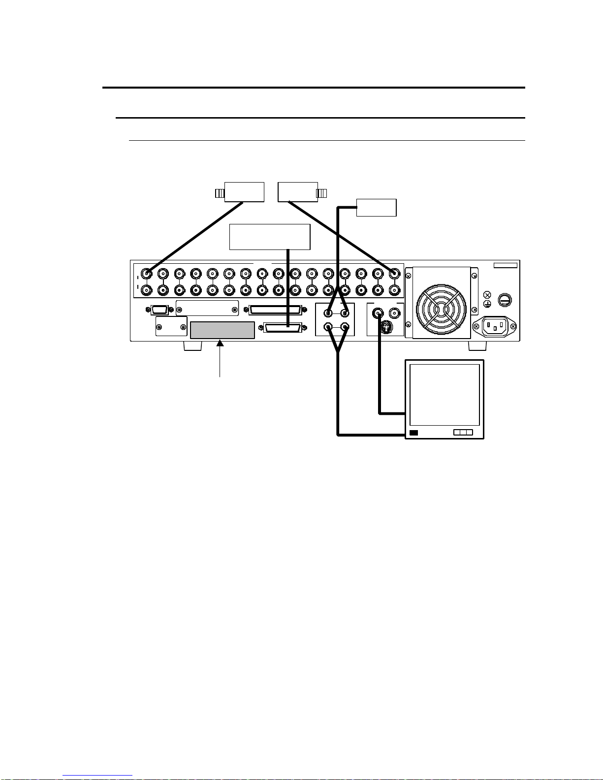
3-1-1. Basic Connection
A basic connection example is given in the figure below.
T4.0A
SCSI68pin(A mphenol)
F
U
S
E
PUSH
SER.No.
131 2 16153 6 107 8 9 1 1 1421 CAMERA
OUT
AUTO
IN
MONITOROUT
IN
RS-232C
OUT
AU DIO
LR
SCSI-A
REMOTE
ALARMY/C
1 2
4 5
75Ω
AC100-240 V-50/6 0HzIN
ALARM device
CAMERA 1 –CAMERA 16
MIC
Termination
connector
Monitor
Must be connected if no
external HDD used.
(Supplied as accessory)

9
3-1-2. Computer / Remote Control Connection
The CDR-16T can be controlled either via a user fabricated remote control device or a
computer. See sec. ‘3-2-1. RS-232C Connector’when controlling via computer. See sec.
‘3-2-2. Remote Connector’when controlling via remote device.
Important
Only one of the connections shown above is normally made
when configuring the CDR-16T for remote control.
Control via RS-232C connector requires use of command and
request codes given in the RS-232C appendix of this manual.
T4.0A
SCSI68pin(A mphenol)
F
U
S
E
PUSH
SER.No.
131 2 16153 6 107 8 9 1 1 1421 CAMERA
OUT
AUTO
IN
MONITOROUT
IN
RS-232C
OUT
AU DIO
LR
SCSI-A
REMOTE
ALARMY/C
1 2
4 5
75Ω
AC100-240 V-50/6 0HzIN
Remote Control
device
(User fabricated)
Computer
Termination
connector
Must be connected if no
external HDD used.
(Supplied as accessory)

10
3-1-3. External Hard Drive Setup
It is possible to expand CDR-16T recording capacity by adding additional external hard
drives. Multiple external hard drives can be connected via the rear panel SCSI connector.
Connection is as illustrated below.
Important
It is possible to expand CDR-16T record capacity by
configuring up to 9 hard drives. Total array is limited to 9
drives, one internal drive + 8 external drives.
Set SCSI ID
The CDR-16T series internal HDD must be assigned SCSI ID number #0. Each
connected external hard drive must be assigned a different SCSI ID number other than #0
(no repeat numbers). Consult drive manual for ID setting procedure at drive unit. If ID settings
are wrong, operations cannot be properly performed.
Termination Connector
The last external HDD in the CDR-16T array must be terminated with the supplied accessory
SCSI termination connector. If last drive is not terminated, operational problems could result.
T4.0A
SCSI68pin(Amphenol)
F
U
S
E
PUSH
SER.No.
131 2 1 6153 6 107 8 9 11 1421
CAMERA
OUT
AUTO
IN
MONITOROUT
IN
RS-232C
OUT
AUD IO
LR
SCSI-A
REMOTE
ALARMY/C
1 2
4 5
75Ω
AC100-240V-50/60HzIN
External
hard disk
drive #1
External
hard disk
drive #2
Up to
external
hard disk
drive #8
Termination
connector
Required at last external HDD in
array. (Supplied as accessory)

11
3-2. Connector Information
3-2-1. RS-232C Connector
See ‘Appendix. RS-232C Control Commands’for command and request codes plus related
information.
uPin Assignment
Pin No. Signal Remarks Direction
1DCD Pins 4/6 repeat –
2TxD Transmit data OUT
3RxD Receive data IN
4DTR Pins 1/6 repeat OUT
5SG Signal ground –
6DSR Pins 1/4 repeat IN
7CTS Transmit ready IN
8RTS Transmit request OUT
9RI NC –
uCable Wiring
An example of computer cable connection for control via RS-232C interface is shown below.
Note that example is based on the use of a PC-AT type (IBM / IBM format) computers that
use straight wired type cables. Cable wiring may differ for other computer models. Consult
your CBC supplier if you need a differently wired cable.
CDR-16T side
RS-232C connector
9-pin D-sub (female)
PC side
RS-232C connector
9-pin D-sub (female)
Signal Pin No. Pin No. Signal
DCD (I) 1 1 DCD (I)
TxD (O) 2 2 RxD( I)
RxD (I) 3 3 TxD (O)
DTR (O) 4 4 DTR (O)
SG (grd) 5 5 SG (grd)
DSR (I) 6 6 DSR (I)
CTS (I) 7 7 RTS (O)
RTS (O) 8 8 CTS (I)
RI (NC) 9 9 RI (NC)
Shell Shell
9-pin D-sub (male)
T4.0A
SCSI68p in(Amp henol)
F
U
S
E
PUSH
SER.No.
1 312 16153 6 107 8 9 11 1421 CAMERA
OUT
AUTO
IN
MONITOROUT
IN
RS-23 2C
OUT
AUD IO
LR
SCSI-A
REMOTE
ALARMY/C
1 2
4 5
75Ω
AC100-240V-50/60HzIN
12
3-2-2. Remote Connector
uPin Assignment
Pin No. Function Pin No. Function
1AUTO SEQ / ALARM RESET 20 VDD OUT
2CAMERA 1 / A 21 SPLIT
3CAMERA 2 / B 22 LIVE / PB
4CAMERA 3 / C 23 REC
5CAMERA 4 / D 24 STOP
6CAMERA 5 / E 25 PLAY
7CAMERA 6 / F 26 JOG
8CAMERA 7 27 SHUTTLE
9CAMERA 8 28 GND
10 CAMERA 9 / 4 –split 29 REC TALLY
11 CAMERA 10 / 5+1 –split 30 STOP TALLY
12 CAMERA 11 / 7+1 –split 31 PLAY TALLY
13 CAMERA 12 / 9 –split 32 JOG TALLY
14 CAMERA 13 / 8+2 –split 33 SHUTTLE TALLY
15 CAMERA 14 / 12+1 (1) –split 34 ADJUST IN
16 CAMERA 15 / 12+1 (2) –split 35 ADJUST OUT
17 CAMERA 16 / 16 –split 36 GND
18 DIAL –A (see page following) 37 GND
19 DIAL –B (see page following)
uCable Connector / Control Signals
Pin core:DC-37PF-N (JAE)
Backshell:DC-C4-J12-S1 (JAE)
Signal: TTL negative pulse or make contact.
Important
Input signal pulse width must be more than 100ms and
interval between pulses more than 100ms.
(Continued following page.)
37-pin D-sub (female)
T4.0A
SCSI68p in(Amphe nol)
F
U
S
E
PUSH
SER.No.
131 2 1 6153 6 1 07 8 9 11 1 421 CAMERA
OUT
AUTO
IN
MONITOROUT
IN
RS-232 C
OUT
AU DIO
LR
SCSI-A
REMOTE
ALARMY/C
1 2
4 5
75Ω
AC10 0-2 40V-50 /60HzIN

13
Remote Control DIAL-A / DIAL-B Signal
Input signals below to remotely turn jog / shuttle dial.
Rotation
Direction Control Signal for DIAL-A and DIAL-B
Rotate left
DIAL-B
(pin 19)
DIAL-A
(pin 18)
Rotate right
DIAL-B
(pin 19)
DIAL-A
(pin 18)
Note
DIAL-A and DIAL-B signal interval must be T ≧ 2ms (see
‘T’above ) and have a 90°phase difference between them.
uREMOTE IN Circuit
Pins 1 –19, 21 –27 and pin 34 (ADJUST IN)
uTALLY / ADJUST OUT Circuit
Pins 29 –33 (TALLY OUTS) and pin 35 (ADJUST OUT)
Input pin
GND pin
C-MOS
buffer
10kΩ
CDR-16T side
5V
0V
5V
0V
5V
0V
5V
0V T
T
(Continued following page.)

14
(
※
Choose resistor value according to type of LED configured in external circuitry.)
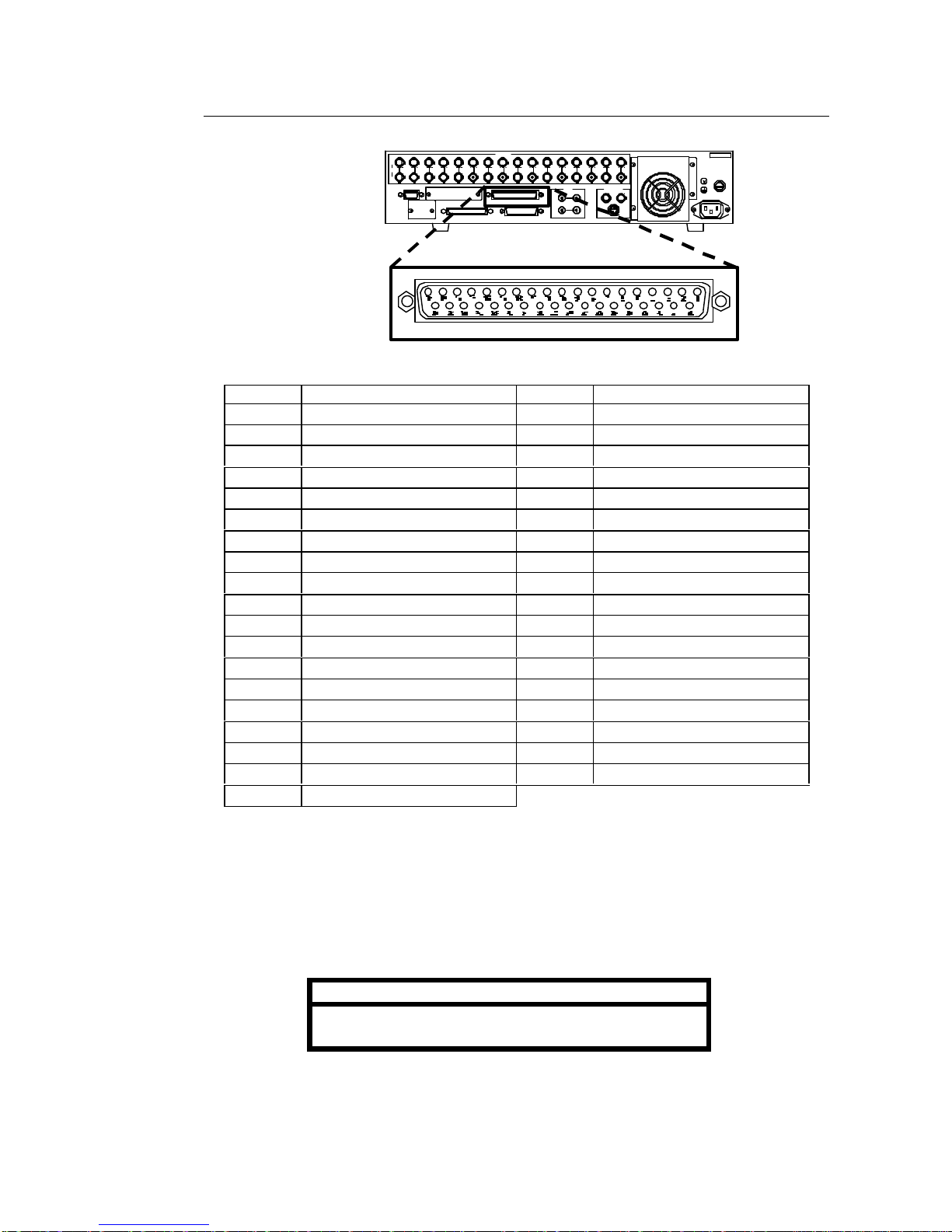
3-2-3. Alarm Connector
uPin Assignment
Pin No. Function Pin No. Function
1ALARM IN1 14 ALARM IN14
2ALARM IN2 15 ALARM IN15
3ALARM IN3 16 ALARM IN16
4ALARM IN4 17 NC (Do not use)
5ALARM IN5 18 NC (Do not use)
6ALARM IN6 19 ALARM OUT (MAKE)
7ALARM IN7 20 ALARM OUT (COM)
8ALARM IN8 21 FAN ALARM (MAKE)
9ALARM IN9 22 FAN ALARM (COM)
10 ALARM IN10 23 HDD ALARM (MAKE)
11 ALARM IN11 24 HDD ALARM (COM)
12 ALARM IN12 25 GND
13 ALARM IN13
Resistor
※
Output pin
Open collector
7406 (TTL)
max. 24VDC 40mA
+ 24VDC
max. power
40mA max.
LED
GND pin
CBC-16T side
25-pin D-sub (female)
T4.0A
SCSI68p in(Amphe nol)
F
U
S
E
PUSH
SER.No.
131 2 1 6153 6 1 07 8 9 11 1 421 CAMERA
OUT
AUTO
IN
MONITOROUT
IN
RS-232 C
OUT
AU DIO
LR
SCSI-A
REMOTE
ALARMY/C
1 2
4 5
75Ω
AC10 0-2 40V-50 /60HzIN
(Continued following page.)
Table of contents


