manuals.online logo
Brands
  1. Home
  2. •
  3. Brands
  4. •
  5. Ciro
  6. •
  7. Motorcycle Accessories
  8. •
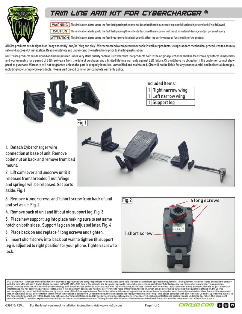
  9. Ciro CYBERCHARGER 50002 User manual

Ciro CYBERCHARGER 50002 User manual

cybercharger™
1 Cybercharger Assembly
1 Baery Power Harness
WARNING:
This indicaon alerts you to the fact
that ignoring the contents described
herein can result in potenal serious
injury or death if not followed.
CAUTION:
This indicaon alerts you to the fact
that ignoring the contents described
herein can or will result in material
damage and/or personal injury.
ATTENTION:
This indicaon alerts you to the fact
if you ignore this detail you will affect
the performance or funconality of
the product.
All Ciro products are designed for
"easy assembly" and/or "plug and
play". We recommend a competent
mechanic install our products, using
standard mechanical procedures to
assure a safe and successful
installaon.
Cybercharger wireless charging informaon:
- Smartphone makers recommend their phones are used in temperatures between 32°F and 95°F. Outside of that
range the phone performance (including baery performance, thus charging) can become irregular.
-Charging rates are regulated by the device being charged. The Cybercharger’s maximum charging rate is 15W.
-If you have a case on your phone. Check with the case supplier to verify it is actually wireless charging compable.
Cases thicker than 5mm or those that include metal or magnets in them may limit or prevent wireless charging,
and should not be used with the Cybercharger.
-The charger will use a standby current of approximately 20mA. If the vehicle has a healthy baery the standby
current draw will not affect baery performance. If the vehicle is likely to sit for more than 2 weeks unplug the
Cybercharger.
-It is normal for the phone and/or charger to become warm during use. If should not become too hot to touch; if it
feels uncomfortably hot, please disconnue use and contact Ciro. It may be a problem with an incompable case or
excessive gap between the phone and coil.
-Use cauon to protect the power cable plug if unplugging and removing the phone holder from the vehicle. The
cable must be secured and protected from water and unintended contact with other surfaces.
G0050002 REV. -
NOTE:
Ciro® warrants that products sold
hereunder to the original purchaser,
if maintained and operated under
normal condions, shall be free from
any defects in materials and
workmanship for a period of (3)
years from date of purchase, and a
lifeme warranty against LED failure.
Ciro will have no obligaon if the
customer cannot show proof of
purchase.
Warranty will not be granted unless
the part is properly installed and
maintained.
Ciro will not be liable for any
consequenal and incidental
damages, including labor, or non-Ciro
products.
Please visit our website Ciro3d.com
for our complete warranty policy.
parts included
FIG.1
(a)
Not included, shown
for illustraon only.
(-)
G0050002 REV. -
PAGE 2
Cybercharger installaon: Install the Ciro accessory ball mount according to the instrucons provided with that product.
1. Remove the large plasc nut (a) from the back of your Cybercharger. Slide the nut over the ball mount (-). FIG.1 (a)(-)
2. Pop the Cybercharger onto the ball and thread the nut onto it. Adjust the angle and then ghten the nut. To change the posion
loosen the nut, move the Cybercharger to the desired angle and then ghten the nut.
3. Connect the baery power harness to the baery and route the power cable to the mounted Cybercharger. Plug the power cable into the
boom of the Cybercharger.
Cybercharger phone fitment and usage:
-The phone holder includes an adjustable boom support leg meant to provide a durable, repeatable locaon for most popular phones. You may
need to loosen the lower most locking screw (b) and adjust the leg (c) to align the wireless charging coil to your phone. All phones are slightly
different and final placement will need to be determined by the user. The locking screw should then be ghtened to prevent unintended move-
ment. FIG.2 (b)(c)
-Do not overly ghten the clamping cam lever (d) before locking into place. Excessive force could lead to phone damage.
-The clamping cam lever (d) can be moved to the opposite side of the Cybercharger. Hold the side arms (e)(f) together and thread the lever all the
way out. Remove the clamping plate (g) and female thread plate (h). Reinstall them on the opposite side. Thread the cam lever back into place in
its new posion.
FIG.2
(a)
(b)
(c)
(d)
(e)
(f)
(g)
(h)
CIRO ACCESSORY PERCH MOUNT
1 Perch Mount
1 Installaon Kit
2 1/4-20 SHCS
2 M6 SHCS
2 Spacers
WARNING:
This indicaon alerts you to the fact
that ignoring the contents described
herein can result in potenal serious
injury or death if not followed.
CAUTION:
This indicaon alerts you to the fact
that ignoring the contents described
herein can or will result in material
damage and/or personal injury.
ATTENTION:
This indicaon alerts you to the fact
if you ignore this detail you will affect
the performance or funconality of
the product.
All Ciro products are designed for
"easy assembly" and/or "plug and
play". We recommend a competent
mechanic install our products, using
standard mechanical procedures to
assure a safe and successful
installaon.
G0050110 REV. C
NOTE:
Ciro® warrants that products sold
hereunder to the original purchaser,
if maintained and operated under
normal condions, shall be free from
any defects in materials and
workmanship for a period of (3)
years from date of purchase, and a
lifeme warranty against LED failure.
Ciro will have no obligaon if the
customer cannot show proof of
purchase.
Warranty will not be granted unless
the part is properly installed and
maintained.
Ciro will not be liable for any
consequenal and incidental
damages, including labor, or non-Ciro
products.
Please visit our website Ciro3d.com
for our complete warranty policy.
parts included
1. Park on a level surface and shut off the motorcycle. Ensure that the engine has me to cool before installaon.
Cover your tank with a clean towel or blanket to protect it.
2. Determine which side of the handlebars you would like the mount. Remove the two screws holding the clamp half in
place. Carefully support the original clamp half and controls to prevent any accidental damage. (Fig. 1)
FIG.1
FIG.3
FIG.2
3. Compare the screws you removed to the screws included in this kit. Both 1/4-20 and M6x1.00 threaded screws are
included to cover a variety of applicaons. Use the screws that match your motorcycle. Prepare the perch mount as
shown above. (Fig. 2)
4. Install the perch mount with spacers to the motorcycle, making sure to re-use the original clamp half. Tighten to factory
specificaons; approximately 72-108 in-lbs (8.1-12.2 Nm). (Fig. 3)
5. The posion of the top ball can be adjusted to provide adequate clearance for any installed accessory. Use a 5/32” hex
key to loosen and adjust the posion, checking final ghtness before riding. (Fig.4)
*If you have purchased any Ciro accessories to go with your ball mount, please refer to those instrucons to complete
your installaon.
FIG.4
FIG.3

Other Ciro Motorcycle Accessories manuals

Ciro TWIN RAIL User manual

Ciro

Ciro TWIN RAIL User manual

Ciro Goldstrike Shock & Awe 2.0 User manual

Ciro

Ciro Goldstrike Shock & Awe 2.0 User manual

Ciro LIGHTED WINDSHIELD TRIM User manual

Ciro

Ciro LIGHTED WINDSHIELD TRIM User manual

Ciro CI59910 User manual

Ciro

Ciro CI59910 User manual

Popular Motorcycle Accessories manuals by other brands

Parkside PSHL 2 D1 Operation and safety notes translation of the original instructions

Parkside

Parkside PSHL 2 D1 Operation and safety notes translation of the original instructions

rizoma Quantum End user manual

rizoma

rizoma Quantum End user manual

Rekluse RadiusCX Read me first

Rekluse

Rekluse RadiusCX Read me first

Rekluse RadiusX Clutch Installation & user guide

Rekluse

Rekluse RadiusX Clutch Installation & user guide

Rekluse Core EXP 2.0 owner's manual

Rekluse

Rekluse Core EXP 2.0 owner's manual

hepco & becker 6307530 00 01 Mounting instructions

hepco & becker

hepco & becker 6307530 00 01 Mounting instructions

LSL 506Y141A FITTING INSTRUCTION

LSL

LSL 506Y141A FITTING INSTRUCTION

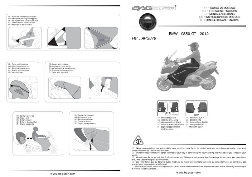
Bagster AP 3076 Fitting instructions

Bagster

Bagster AP 3076 Fitting instructions

Sena 50S quick start guide

Sena

Sena 50S quick start guide

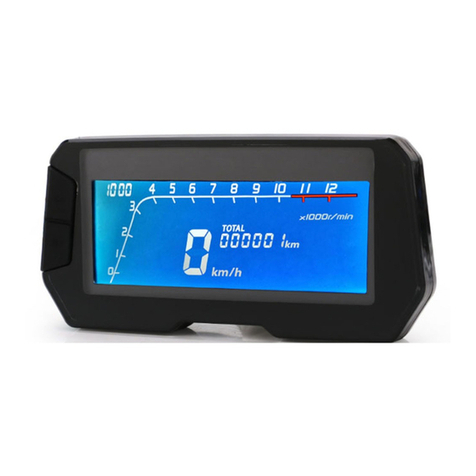
Eling MLS052 instruction manual

Eling

Eling MLS052 instruction manual

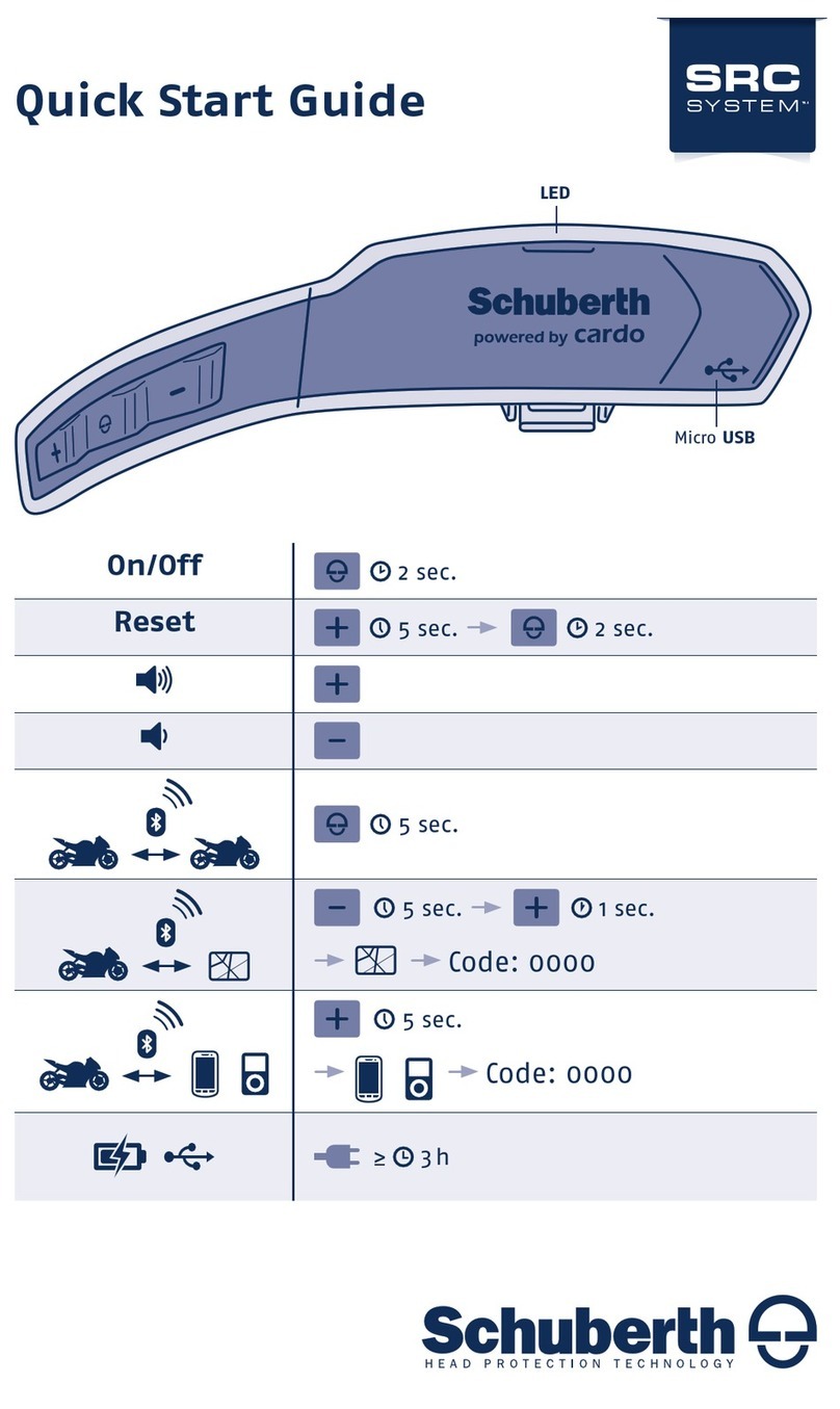
SCHUBERTH SRC system 9049100303 quick start guide

SCHUBERTH

SCHUBERTH SRC system 9049100303 quick start guide

hepco & becker C-Bow 630.4522 Assembling instructions

hepco & becker

hepco & becker C-Bow 630.4522 Assembling instructions

Dräger HPS 7000 Basic Instructions for use

Dräger

Dräger HPS 7000 Basic Instructions for use

tech air 5 user guide

tech air

tech air 5 user guide

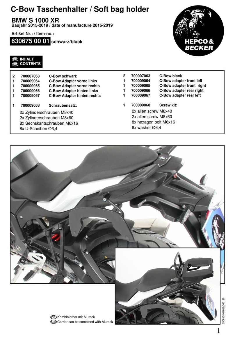
hepco & becker 630675 00 01 quick start guide

hepco & becker

hepco & becker 630675 00 01 quick start guide

Vetter Floating Mount Saddle Bags Owner's manual and mounting instructions

Vetter

Vetter Floating Mount Saddle Bags Owner's manual and mounting instructions

LAZER TANGO user guide

LAZER

LAZER TANGO user guide

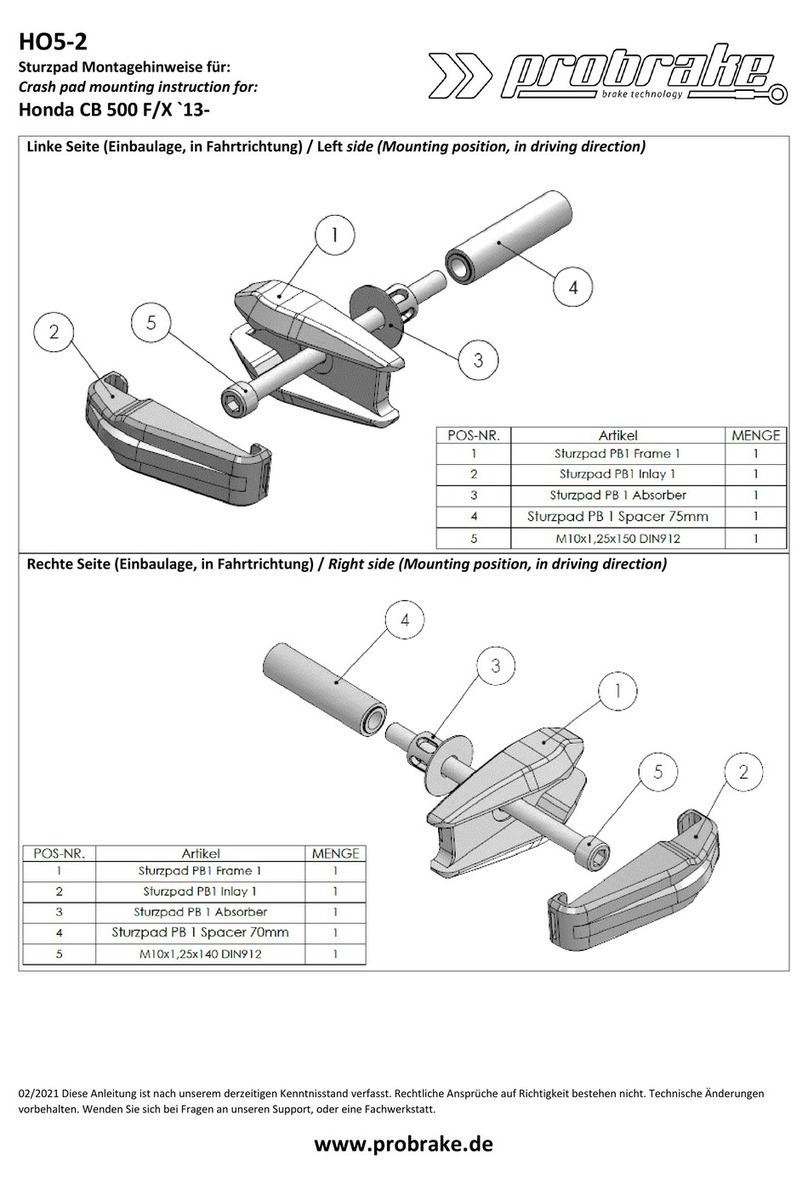
probrake HO5-2 Mounting instruction

probrake

probrake HO5-2 Mounting instruction

manuals.online logo
manuals.online logoBrands
  • About & Mission
  • Contact us
  • Privacy Policy
  • Terms and Conditions

Copyright 2025 Manuals.Online. All Rights Reserved.