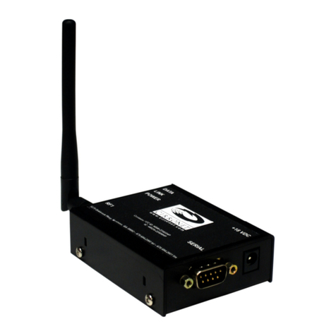
Cirronet ZN-241GU User manual

ZN-241GU
802.15.4 Radio
User’s Guide
3079 Premiere Pkwy, Ste. 140
Duluth, Georgia 30097
www.cirronet.com
+1 678 684-2000

Important Regulatory Information
Cirronet Product FCC ID: HSW-ZN241
IC 4492A-ZN241
Note: This unit has been tested and found to comply with the limits for a Class A
digital device, pursuant to part 15 of the FCC Rules. These limits are designed to
p
rovide reasonable protection against harmful interference when the equipment is
operated in a commercial environment. This equipment generates, uses, and can
radiate radio frequency energy and, if not installed and used in accordance with the
instruction manual, may cause harmful interference to radio communications.
Operation of this equipment in a residential area is likely to cause harmful interference
in which case the user will be required to correct the interference at their expense.
FCC s MPE Requirements
Information to user/installer regarding FCC s Maximum Permissible
Exposure (MPE) limits.
Notice to users/installers using the following mobile antennas, with Cirronet RF products:
ZN241 5 dBi and 2 dBi Omni Antennas
The field strength radiated by any one of these antennas, when connected to Cirronet RF
products, may exceed FCC mandated RF exposure limits. FCC rules require professional
installation of these antennas in such a way that the general public will not be closer than
20 cm from the radiating aperture of any of these antennas. End users of these systems
must also be informed that RF exposure limits may be exceeded if personnel come closer
than 20 cm to the apertures of any of these antennas.

Getting Started
The ZN-241GU Starter Kit contains all of the items show below. Before
starting, identify each of the items in your kit.
The ZN-241GU radio is a simple-to-use, simple-to-setup wireless
networking device. With its Auto-Config mode, all that is needed to send
data between two ZN-241Gs is to attach the antennas, connect the
radios to serial ports and plug in the power supplies. Optionally, the ZN-
241GU can be powered off the USB port. Each step is described below.
Identifying Indicators, Connectors and Ports
1

Attaching the Antenna
The ZN-241GU radio is supplied with a foldable antenna with a screw
type connector. Attach the antenna to the ZN-241GU by threading the
antenna onto the antenna connector on the rear of the ZN-241G, turning
until finger tight. Fold the antenna at a right angle so the antenna is
sticking up above the ZN-241G.
If the folding part of the antenna is not in the right position to stick up
above the ZN-241G, hold onto the knurled bottom of the antenna and
twist the upper part of the antenna until the foldable part of the antenna
sticks up above the ZN-241G. DO NOT TWIST THE ENTIRE ANTENNA
AS THIS MAY DAMAGE THE ANTENNA.
Repeat this step with the other ZN-241G.
2

Connecting the ZN-241GU to a Computer
The ZN-241GU is designed to connect to a USB port of a personal
computer. Using one of the USB cables provided, connect one end to a
USB port on your computer and the other end to the USB connector on
the rear of the ZN-241GU.
3

Applying Power to the ZN-241G
Connect one of the power supplies to one of the ZN-241Gs using the
power supply connector on the rear of the ZN-241G.
Connect the wall-mount end of the power supply to a wall outlet with
either 110VAC or 220VAC. The Power LED on the ZN-241GU will come
on and after a moment the Data LED will blink. The Data LED blinking
means the ZN-241GU is looking for another ZN-241GU to link to.
Repeat this step with the other ZN-241G. After a few seconds, the Link
LEDs on both ZN-241Gs will be lit. This indicates that the two ZN-241Gs
have established a wireless link.
Installing the USB drivers
When the ZN-241GU is attached to the computer and power applied,
your computer will indicate a new device has been found. Follow the
steps of the installation wizard and indicate the drive where you have
inserted the ZN-241G Software & Manuals CD is where the computer
can find the drivers. Complete the installation process before continuing.
Sending and Receiving Data
To send and receive data, a communications program is required. You
will need two PCs, one for each ZN-241GU. Most PCs come with a
communications program called Hyper Terminal. This can be found by
clicking on Start, then All Programs, then Accessories, then
Communications then Hyper Terminal. The following screen will display.
4

When Hyper Terminal starts, it asks you to name the connection. Enter
ZN-241G and click OK.
Hyper Terminal will then ask you how you want to connect. Ignore the
boxes for country code and area code and click on the drop down arrow
on the bottom window labeled Connect Using. Select the serial port to
which you have connected the ZN-241GU (this will usually be COM1) as
shown below.
When you click OK, a window will open up labeled COM1 Properties (or
whatever COM port you selected) with a tab labeled Port Settings as
shown below.
5

In the Bits per Second window, select 38400. Make sure the other
windows show 8, None, 1 and Hardware. Click Apply and then OK.
You will now be at a window labeled ZN-241G-Hyper Terminal.
Verify the Link LEDs on both ZN-241Gs are on steady. On one computer
type characters on the computer keyboard of one computer and verify
they are displayed on the screen of the other computer as shown below.
Repeat this process using the second computer to send characters to
the first computer.
6

Note: If you press the Enter key, Hyper Terminal will move the cursor to
is
you
erminal
send a line feed when the Enter key is pressed.
Congratulations! You have just set up a wireless network. If you want to
change your network configuration, please refer to the next section which
describes the ZNWizard program. ZNWizard is a Windows-based utility
which makes it simple to setup the ZN-241G.
ZNWizard
ZNWizard can be found on the Software CD. It is an easy to use,
program that allows you to change various radio parameters in a GUI
(graphical user interface) format. Double click on znwizard.exe and the
following screen will appear.
the start of the line but will NOT move it down the screen. Any keys then
typed will overwrite the previously typed characters on that line. This
the way Hyper Terminal works and is not a problem with the radio. If
want, consult Hyper Terminal’s Help files on how to have Hyper T
7

Select Comm Port Settings
Connect and the Select Comm Port Settings dialog will di
n below. The “OK” after COM1 in the dialog below in
1 port on the computer is available. Ports that are not ava
ead of OK.
Click on splay
as show dicates that
the COM ilable
have N/A inst
The Select Comm Port Settings dialog is pre-loaded with settings the
ZN-241GU has when it ships from the factory. In most instances, simply
clicking OK will allow ZNWiza
rd to find the radio and load the main
program t, the radio
sing
two method
gs for
Comm Po s.
Obvious ing. If,
a secon
window. If, however, the default settings are incorrec
will not be found. This screen allows you to connect to the radio u
s.
The first is to use the drop down menus to change the default settin
rt, Baud Rate, Parity and Stop Bits to the correct value
ly, this assumes you know which settings the radio is us
however, those parameters may have been changed and are not known,
d method is available.
8

The Auto Detect Function
The Auto Detect function works this way. If set to FALSE, once OK is
selected, the program uses the default settings to try to communicate
with the radio. If set to TRUE, the program will begin a systematic
process beginning with the first valid port (COM 1 in most cases) then
ill cycle through each combination of settings until a radio is found.
epending on what values the radio requires, this could take a few
moments. However, once the settings have been found, the Current
Settings window will display the ZN-241GU settings, the Connect button
will change to Disconnect
The Main Program Window
w
D
T
read
his is the main ZN Wizard program window. On the left side is a
out of the current settings for the radio. On the right side are radio
ction in
Device Mode since that selection is set automatically in Auto-Config
mode.
parameters that can be modified. The parameters are grouped according
to function.
When a value in a field is grayed out, that means it cannot be changed
due to some other setting that has been selected. For example, if
Network is set to Auto-Config, you are not able to make a sele
9

Configuration Fields
The following table is a description of the Configuration Fields grouped
into the three sections (Network Settings, Radio Comm Settings and
Channel Mask) of the ZNWizard main window. In the center of the
window is a box labeled “Network Settings”. The first drop down menu
labeled “Network” as shown below.
Network
dialog
is
This setting selects the type of network of ZN-
241Gs you would like to set up. The three
choices are:
Au
radio. Only a radio configured as a Base can be
set to Multipoint. All Remotes in a Multipoint
network must be set to Point-to-point mode.
to-Config —This is a network with only two
this is called a Point-to-point Network). In
e, one of the two radios will
automatically make itself the base radio and the
other will remain a remote. In a point-to-point
network, it doesn’t matter which ZN-241GU is
the base and which is the remote.
Point-to-Point — This is also a network with
only two radios. In this mode, rather than having
the radios decide which will be the base and
which will be the remote, you must set one
radio, and only one radio, to be the base. It
doesn’t matter which radio is set to be the base.
This mode is useful when there are multiple
point-to-point networks in the same area to
make sure the right two radios connect.
Multipoint — This is a network with more than
two radios (this is sometimes called a Point-to-
Multipoint Network). In this type of network, one
transmitted to the base radio and only the base
radios (
this mod
radio and only one radio must be set to be the
base. All of the data sent to the base is
transmitted to all of the other radios in the
network. Data sent to any remote is always
10

The four other fields under Network Settings are described below.
Device Mode
Note: If Auto-Config is selected in the
Network setting field, ZNWizard will not le
set the radio as a Base or Remote.
This is how a radio is set to be a Base or a
Remote radio when either Point-to-Point or
Multipoint mode is selected for the type of
network. Only one radio in a network can be
the base.
t you
Network ID
The Network ID is a way to make sure tha
the right two radios connect when there are
multiple networks of ZN-241Gs in the same
location. In fact, ZN-241GU radios can ONL
connect with other ZN-241Gs with the same
Network ID. The Network ID can be any
number between 1 and 65,534.
t
Y
TX Timeout
whatever data it has already received. If
is no pause in the data being sent to the ZN
241G, the radio will wait until it has received
109 bytes of data before transmitting the
The default value of 5 milliseconds (5
thousandths of a second) should work for
most applications. This value can range from
5 to 255 (equal to a pause of about ¼
second).
When data is being sent to a ZN-241GU by a
computer or other device, any time there is a
pause in the data as long as the time specified
by TX Timeout, the ZN-241GU will transmit
there
-
data.
TX Attempts
when it doesn’t go through. The ZN-241GU
will try the number of times entered in TX
Attempts. Multipoint mode is a special case
multipoint mode, it isn’t possible for the bas
to know if all of the remotes got the data.
when the network type is Multipoint, e
batch of data transmitted will be sent T
Attempt times, even if it was received by all of
the remotes on earlier attempts. The ZN-
241GU automatically makes sure that
regardless of how many times the data
sent, it is sent out the serial port only onc
When data is sent wirelessly, it doesn’t always
go through on the first attempt. The ZN-
241GU automatically retransmits the data
. In
e
So
very
X
was
e.
1
1

The Radio Comm Settings change the serial port settings on the ZN-
241G. Th t op es
the s t d ou
make tin ically
changes the settings on your
Baud
Rate
e dialog box tha
ettings for your PC bu
changes to these set
ens when you first start ZNWizard chang
oesn’t change the radio settings. When y
gs in the ZN-241G, ZNWizard automat
PC so you can still talk to the radio.
This is the speed that the ZN-241GU talks to other devices
through its s by 10 to
find out how
from the ZN
the ZN 41G 41GU
supports the stand
erial port. You can divide the baud rate
many bytes per second data will be sent to and
-241G. The baud rate does not change how fast
U sends data over the air. The ZN-2-2 ard PC baud rates from 4800 to 115,200.
Parity Bit The parity b to
make sure d
ed fr
ed
it is an error-checking bit that can be used
ata is received correctly over the serial port. It
equently in the early days of computers but is
today.
was us
rarely us
Stop Bits Stop bits ar
where one b
to 1 for mos
supports bo
e used in serial communications to indicate
yte stops and another begins. It is typically set
t serial communications. The ZN-241GU
th 1 and 2 stop bits.
Ch
Mask
The ZN
to comm
-241
uni e
channels on
other, radio
Sometimes
same locati
radios on an l.
The Channe to.
The ZN-241
automaticall
You can let
all of the 16 l.
When more will
listen on the o
that is too “l
channel that is “quiet.” The ZN-241GU will use this “quiet
channel” to set up the network.
GU has 15 different wireless channels it can use
cate. The channels in the ZN-241GU are lik
a radio or TV station. In order to hear each
s must be “tuned” to the same channel.
when other networks of ZN-241Gs are in the
on, radios on one Network ID might interfere with
other Network ID if they use the same channe
l Set lets you choose which channel to “tune”
GU has a special feature that allows it to
y select the best channel to set up the network.
the ZN-241GU pick from one, two, three, up to
channels when selecting the best channe
than one channel is selected, the ZN-241GU
first channel selected. If it hears another radi
oud” it will try another channel until it finds a
annel
12

Adva
ions,
p r to the
C ch Sup
nced Setup
The ZN-241GU is a very capable and flexible radio. The features and
functions described in this manual, while sufficient for most applications,
are only a subset of the complete set. For more advanced applicat
lease refe
irronet Te Technical Reference Manual on the CD or contact
port (support@cirronet.com).
ardware Requirements
Specifications/H
•Star topology w/limited peer-to-peer capability. 1 base, up to 60 remotes.
•Single-hop mesh store-and-forward to enable routing around dead spots.
•Operating Ban 483.5 MHz
•re
•te:
•Channel Chipping
•Modulation: MSK with Raised Cosine Filtering
•Certification Type: DTS device per FCC 15.247 and ETS 300-328
•d
•Receiver Sensitivi
•Link Margin: 110 dB (approximately 3 Km LOS propagation)
•Adjacent Ch. Rejection: >39 dB with jammer @ 5 MHz offset
•ut:
•5.5
•onsump
•Operating Temp R
•Humidity: 95% N
•RF Connector: R
•Host Connector: U
M-2400-2003 ZN241G User’s Guide Rev A
d: 2400-2
Radio Type: Di
Channel Bit Ra
ct Sequence (DTS), IEEE 802.15.4 PHY layer
250 Kbps
Rate: 2 Mcps
RF power: +17 Bm typical, +15 dBm minimum
ty: -98 dBm typical, -95 dBm minimum
Spurious Outp
Input Voltage:
Current C
Per FCC 15.247 and ETS 300-328
volts minimum, 6 volts nominal, 7 volts max
tion: 70 mA typical operating, 180 mA peak (transmit)
ange: -40 C to + 70 C
on-condensing
everse SMA
SB Type B
1
3

Warranty
Seller warrants solely to Buyer that the goods delivered hereunder shall b
free from defects in materials and workmanship, when given normal, proper
and intended usage, for twelve (12) months from the date of delivery to
Buyer. Seller agrees to repair or replace at its option and without cost t
Buyer all defective goods sold hereunder, provided that Buyer has gi
Seller written notice of such warranty claim within suc
e
o
ven
h warranty period. All
goods returned to Seller for repair or replacement must be sent freight
er a Return
no obligation
al wear and
ence
the
al to
to, power failure. No suit or action shall
an twelve (12) months after the related
ot rely on any
ing the goods sold hereunder, and any oral
Seller and shall not be a part of any warranty.
OREGOING WARRANTY ARE IN LIEU OF
ESS OR IMPLIED, WRITTEN
OR MERCHANT ABILITY OR
LIABILITY
LE OR SUPPLYING OF THE
, WHETHER BASED UPON
HALL NOT EXCEED
HE GOODS. IN
R ANY OTHER
NSEQUENTIAL
OF PROFITS,
ARISING OUT OF THE
HE GOODS. THE
D SHALL NOT
DING,
prepaid to Seller’s plant, provided that Buyer first obtain from Sell
Goods Authorization before any such return. Seller shall have
to make repairs or replacements which are required by norm
tear, or which result, in whole or in part, from catastrophe, fault or neglig
of Buyer, or from improper or unauthorized use of the goods, or use of
goods in a manner for which they are not designed, or by causes extern
the goods such as, but not limited
be brought against Seller more th
cause of action has occurred. Buyer has not relied and shall n
oral representation regard
representation shall not bind
THE PROVISIONS OF THE F
ANY OTHER WARRANTY, WHETHER EXPR
OR ORAL (INCLUDING ANY WARRANTY
FITNESS FOR A PARTICULAR PURPOSE). SELLER’S
ARISING OUT OF THE MANUFACTURE, SA
GOODS OR THEIR USE OR DISPOSITION
WARRANTY, CONTRACT, TORT OR OTHERWISE, S
THE ACTUAL PURCHASE PRICE PAID BY BUYER FOR T
NO EVENT SHALL SELLER BE LIABLE TO BUYER O
PERSON OR ENTITY FOR SPECIAL, INCIDENTAL OR CO
DAMAGES, INCLUDING, BUT NOT LIMITED TO, LOSS
LOSS OF DATA OR LOSS OF USE DAMAGES
MANUFACTURE, SALE OR SUPPLYING OF T
FOREGOING WARRANTY EXTENDS TO BUYER ONLY AN
BE APPLICABLE TO ANY OTHER PERSON OR ENTITY INCLU
WITHOUT LIMITATION, CUSTOMERS OF BUYERS
3079 Premiere Pkwy, Ste. 140
Duluth, Georgia 30097
www.cirronet.com
+1 678 6 4-20008
Table of contents
Other Cirronet Radio manuals
