Cirronet HN 210D User manual

HN 210D/X – HN214D/X
RS-232 Serial Modbus Radio
User’s Guide

Important Regulatory Information
Cirronet Product FCC ID: HSW-2410
IC 4492A-2410
Note: This unit has been tested and found to comply with the limits for a Class A digital device, pursuant to
p
art 15 of the FCC Rules. These limits are designed to provide reasonable protection against harmful
interference when the equipment is operated in a commercial environment. This equipment generates,
uses, and can radiate radio frequency energy and, if not installed and used in accordance with the
instruction manual, may cause harmful interference to radio communications. Operation of this equipment
in a residential area is likely to cause harmful interference in which case the user will be required to correct
the interference at their expense.
FCC s MPE Requirements
Information to user/installer regarding FCC s Maximum Permissible Exposure (MPE) limits.
Notice to users/installers using the 24 dBi parabolic dish antenna in conjunction with all Cirronet
RF products.
FCC rules limit the use of this antenna, when connected to Cirronet RF products for point-to-point
applications only. It is the responsibility of the installer to ensure that the system is prohibited from
being used in point-to-multipoint applications, omni-directional applications, and applications where there
are multiple co-located intentional radiators transmitting the same information. Any other mode of
operation using this antenna is forbidden.
Notice to users/installers using the following fixed antennas, with Cirronet RF products:
Andrews 24dBi parabolic dish
Andrews 18dBi parabolic dish
Cushcraft 15dBi Yagi,
Mobile Mark 14dBi Corner Reflector,
Mobile Mark 9dBi Corner Reflector
The field strength radiated by any one of these
antennas, when connected to Cirronet RF
products, may exceed FCC mandated RF
exposure limits. FCC rules require
professional installation of these antennas in
such a way that the general public will not be
closer than 2 m from the radiating aperture of
any of these antennas. End users of these
systems must also be informed that RF
exposure limits may be exceeded if personnel
come closer than 2 m to the apertures of any of
these antennas.
Notice to users/installers using the following mobile antennas, with Cirronet RF products:
Mobile Mark 12dBi omni-directional,
Mobile Mark 9dBi omni-directional,
MaxRad 5dBi whip,
Cirronet Patch antenna,
Ace 2dBi dipole,
Mobile Mark 2dBi Stub
The field strength radiated by any one of these
antennas, when connected to Cirronet RF
products, may exceed FCC mandated RF
exposure limits. FCC rules require professional
installation of these antennas in such a way
that the general public will not be closer than
20 cm from the radiating aperture of any of
these antennas. End users of these systems
must also be informed that RF exposure limits
may be exceeded if personnel come closer
than 20 cm to the apertures of any of these
antennas.

Declaration of Conformity
Warning! The RLAN transceiver within this device uses a band of frequencies that are not completely harmonized within the
European Community. Before using, please read the European Operation Section of the Products User’s Guide for limitations.
0889 is the identification number of RADIO FREQUENCY INVESTIGATION LTD - Ewhurst Park, Ramsdell RG26 5RQ
Basingstoke, United Kingdom – the Notified Body having performed part or all of the conformity assessment on the product.
The WIT2410 to which this declaration relates is in conformity with the essential requirements
of the R&TTE directive 1999/5/EC and complies with the following standards and/or other
normative documents:
For Interfaces For RLAN Transceiver
EN 55022
EN 55024
EN 300 328
EN 301 489 -1, -17
EN 60950
Canadian Department of Communications Industry Canada (IC) Notice
Canadian Department of Communications Industry Canada (IC) Notice
This apparatus complies with Health Canada’s Safety Code 6 / IC RSS 102.
"To prevent radio interference to the licensed service, this device is intended to be operated
indoors and away from windows to provide maximum shielding. Equipment (or its transmit
antenna) that is installed outdoors may be subject to licensing."
ICES-003
This digital apparatus does not exceed the Class B limits for radio noise emissions from
digital apparatus as set out in the radio interference regulations of Industry Canada.
Le présent appareil numérique n'émet pas de bruits radioélectriques dépassant les limites applicables aux appareils
numériques de Classe B prescrites dans le règlement sur le brouillage radioélectrique édicté par Industrie Canada.

WARNING!!
≡≡≡≡≡≡≡≡≡≡≡≡≡≡≡≡≡≡≡≡≡≡≡≡≡≡≡≡≡≡≡≡≡≡≡≡≡≡≡≡≡≡≡
For our Customers who wish to use this product in hazardous locations.
The HN-210D, HN-210DX, HN-214D and HN-214DX radios have been tested by Underwriters
Laboratories Inc. for use in Class I, Division 2, Groups A, B, C, and D Hazardous Locations as
specified in UL1604 and UL/C-UL/Zones(UL2279).
Such areas may have Explosive Gases.
To install these radios in this environment the following steps must be implemented.
The power supply used with the product must be a UL Class 2 rated device.
1) Contract a Qualified Licensed Electrician to install and run the power wiring from a
screw type, hard wired 12 VDC 1A Class 2 Output power supply in a UL Listed Box and
route a conduit to the radio which must be installed in a UL Listed Box suitable for the
environment. The conduit must be gas tight so no gases can flow through conduit.
2) Any Cirronet products with outdoor radio transceivers (tower mounted) marked for
Hazardous Locations must have the interconnecting multi-conductor cable run in
approved conduit for the hazardous location. The cable must be in the conduit until out
of the Hazardous Location and the conduit must be gas tight so no gases can flow
through conduit.
3) Do NOT remove the power connector to the device while circuit is live. Disconnect
power only while circuit is dead, or the location is known to be non-hazardous. Failure to
do so, may result in a “Risk of Fire or Explosion”
Only then is the unit suitable for a hazardous location.
For more information on Hazardous Locations contact UL and ask for UL1604
requirements. www.ul.com
RF Exposure
WARNING: End Users of these systems must be informed that RF exposure limits
may be exceeded if personnel come closer than 45 cm to the antenna aperture when
exceeding 9 dBi of gain in conjunction with the transceiver.
Repairs
Cirronet does not recommend field repairs of the radio equipment. Surface Mount
Technology (SMT) has been used in the production of the transceiver module, which
requires specialized training and equipment for proper servicing. The equipment
should be returned to the factory for any repair.

Table of Contents
Introduction .................................................................................................................. 1
HopNet Benefits...........................................................................................................1
Operating Frequency ............................................................................................... 1
HopNet Frequency Hopping Spread Spectrum Advantages....................................1
HopNet Data Integrity............................................................................................... 2
Flexible Power Management....................................................................................2
Advanced Features...................................................................................................... 3
The HopNet Family of Products ................................................................................... 3
Accessories..............................................................................................................3
Getting Started................................................................................................................4
Install the HopNet Configuration Wizard on a PC. .......................................................4
Connect the HopNet radio to the PC............................................................................4
Set one HopNet radio to act as the base...................................................................... 5
Run a communications test..........................................................................................7
The Serial Adapter Box................................................................................................ 8
3 Wire Operation...................................................................................................... 8
Remote Pin-Out, RS-232.........................................................................................9
Guidelines for Installation........................................................................................... 10
Aiming the Antenna and Placing the Remote.............................................................10
Interconnect Cable..................................................................................................... 10
Configuring the Network................................................................................................ 11
HopNet Configuration Wizard (5.0 or later)................................................................ 11
About the INIT.INI File................................................................................................ 12
Parameters Tab ..................................................................................................... 13
Network Tab........................................................................................................... 17
Protocol Tab...........................................................................................................20
RF Tools ................................................................................................................ 22
WinCom Window.................................................................................................... 26
Function Keys ........................................................................................................ 29
Recover.................................................................................................................. 29
Restart ...................................................................................................................30
Saving Configurations................................................................................................ 30
About Protocols.......................................................................................................... 30
Modbus Operation...................................................................................................... 32
Automatic Addressing............................................................................................33
DNP3/DF1 Operation................................................................................................. 33
European Union Operation......................................................................................... 34
Configuration Commands.............................................................................................. 35
Serial Commands....................................................................................................... 36
Network Commands................................................................................................... 38
Protocol Commands................................................................................................... 41
Status Commands...................................................................................................... 44
Memory Commands...................................................................................................46
Adapter Commands ................................................................................................... 47
Modem Command Summary ..................................................................................... 48

Troubleshooting ............................................................................................................49
Overview....................................................................................................................49
Introduction ............................................................................................................49
Transceiver Requirements.....................................................................................49
Common System Problems........................................................................................ 50
Guidelines for Reducing Interference.........................................................................51
Introduction ............................................................................................................51
Guidelines for Setting Up the Network...................................................................51
Guidelines for Selecting Your Site.......................................................................... 51
Guidelines for Avoiding Terrain Obstructions............................................................. 52
Customer Support...................................................................................................... 53
Introduction ............................................................................................................53
Technical Assistance ............................................................................................. 53
Factory Repairs...................................................................................................... 53
Technical Specifications................................................................................................54
Electrical ................................................................................................................54
Mechanical............................................................................................................. 55
Environmental........................................................................................................ 55
Glossary of Terms......................................................................................................... 56
Warranty........................................................................................................................ 58

HopNet RS-232 Serial ModBus Radio
Introduction
The HopNet family of products provides reliable wireless connectivity for either
point-to-point or point-to-multipoint applications. HopNet products are built around
the WIT2410 radio transceiver, which employs frequency hopping spread spectrum
technology. This technology ensures:
•Maximum resistance to noise
•Maximum resistance to multipath fading
•Robustness in the presence of interfering signals
The HN-210D and HN-210DX are NEMA 4X weatherproof versions of the HopNet
product line. The HN-214D, which is a HN-210D with a 4 ft. cable, is also available.
The interface to the HopNet D and DX versions allows the Host to communicate with
the Remote unit through an integrated 50 ft (15 meter) cable. The HopNet D and DX
versions can act as either Bases or Remotes.
The HopNet D Remote has an internally mounted 6 dBi patch antenna. The built-in
antenna of the HopNet D case greatly eases outdoor installation since no antenna
feedline cable or adapters are needed. The 6 dBi antenna gain increases the radiated
EIRP to +24 dBm and the effective receiver sensitivity to –99 dBm. The HopNet DX
has a TNC connector for attaching one of the following external antennas:
OMNI242 OMNI249
OMNI2412 YAGI2415
RWA242 RWA249
CORNER249 CORNER2414
PAR2418 PAR2424
HopNet Benefits
The HopNet family of products is built with rugged enclosures compliant with IP 66
and NEMA 4X standards for outdoor and harsh industrial environments. All Hopnet
products work with each other and can be mixed and matched in a single network. All
HopNet Products are WIT2410 compatible and can be used with WIT2410 OEM
based products as well as with the SNAP 2410 10/100Base T access point.
Operating Frequency
The HopNet family operates in the 2.4 GHz ISM band that allows for license-free use
and worldwide compliance.
HopNet Frequency Hopping Spread Spectrum Advantages
In the frequency domain, a multipath fade can be described as a frequency selective
notch that shifts in location and depth over time. Multipath fades typically occupy
five percent of the band. A conventional radio system typically has a five percent
chance of signal impairment at any given time due to multipath fading.
©2000- 2004 Cirronet™Inc 1 M-2410-0022 Rev B

HopNet RS-232 Serial ModBus Radio
Frequency Hopping Spread Spectrum reduces the vulnerability of a radio system to
interference from jammers and multipath fading by distributing or spreading the
signal over a larger region of the frequency band.
The fade resistant, HopNet frequency-hopping technology employs up to 75 channels
and switches channels over 100 times a second to achieve high reliability throughput.
HopNet Data Integrity
An on-board 3 KB buffer and error correcting over-the-air protocol ensure data
integrity even in the presence of weak signals or jammers. The serial interface
handles both data and control of asynchronous data rates of up to 230 Kbps.
Flexible Power Management
The power can be set at 10 milliwatts or 100 milliwatts using the included software.
Reduced power can reduce the size of the coverage zone, which may be desirable for
multiple network indoor applications. You can also place the transceiver module in a
power-save mode, which enables smart power management. Smart power
management allows a remote unit to drop into a lower current standby mode during
transmission or receiving gaps. This feature also allows HopNet products to be used
in various countries where the output power requirements may vary due to regulation.
©2000- 2004 Cirronet™Inc 2 M-2410-0022 Rev B

HopNet RS-232 Serial ModBus Radio
Advanced Features
HopNet modems have many advanced features:
•Employ frequency hopping technology with up to 75 channels in the 2401 to
2475 MHz frequency range
•Support digital addressing for up to 64 networks, with 62 remotes per
network.
•Use transparent ARQ protocol
•Use same hardware for all supported data rates
•Supports up to 230 Kbps asynchronous data rates
•Full Duplex operation
•Store setup configuration in nonvolatile memory (FLASH)
•Fast acquisition – less than 2 seconds is the typical time to acquire hopping
pattern
•Smart power management features
The HopNet Family of Products
The HopNet family consists of the following products:
Accessories
Antennas
Adapter
Power Supplies
©2000- 2004 Cirronet™Inc 3 M-2410-0022 Rev B

HopNet RS-232 Serial ModBus Radio
Getting Started
A pair of HopNet radios are set up by performing the following steps:
•Install the HopNet Wizard configuration program on a PC
•Connect the HopNet radio to the PC
•Set one HopNet radio as a base radio
•Run a communications test
These steps are described in detail below. Other steps you may want to perform
include:
•Change the baud rate
•Change the radio network number
•Change how fast the radios change frequencies
Refer to the Configuring the Network section of this manual for details on these steps.
Install the HopNet Configuration Wizard on a PC.
The HopNet Configuration Wizard is located on the software and documentation CD
included in the HopNet radio package. Install the program by inserting the CD in the
PC and following the installation wizard. If autorun has been turned off, double-click
on setup.exe on the CD to start the wizard.
Connect the HopNet radio to the PC.
Plug one end of the serial cable provided to a serial port on the PC.
©2000- 2004 Cirronet™Inc 4 M-2410-0022 Rev B

HopNet RS-232 Serial ModBus Radio
Connect the other end of the serial cable to the DIN rail serial adapter box.
Connect the end of the cable (RJ-45 connector) from the HopNet radio to the DIN rail
serial adapter box.
NOTE: Make sure the RUN/CONFIG switch is in the CONFIG position.
Connect power to the HopNet radio by plugging one end of the wall-mount power
supply into the serial adapter box and the other end into a wall outlet. A green LED
on the serial adapter box will turn on indicating power is present.
Set one HopNet radio to act as the base.
CAUTION: When using a USB to RS-232 adapter, the HN Wizard may not be able
to detect if the HopNet radio is disconnected from the computer. If the HopNet
radio is disconnected from the computer, it is necessary to click on the Restart
button on the HN Wizard screen. This will reload the settings from the radio in
case a different radio has been connected.
When using HopNet radio, one unit, and only one, must be set as the base. All other
HopNet radios must be set as remotes. With a HopNet radio connected to the PC,
start the HopNet Configuration Wizard program by double-clicking on the icon on the
desktop. The HopNet Configuration Wizard will automatically detect which serial
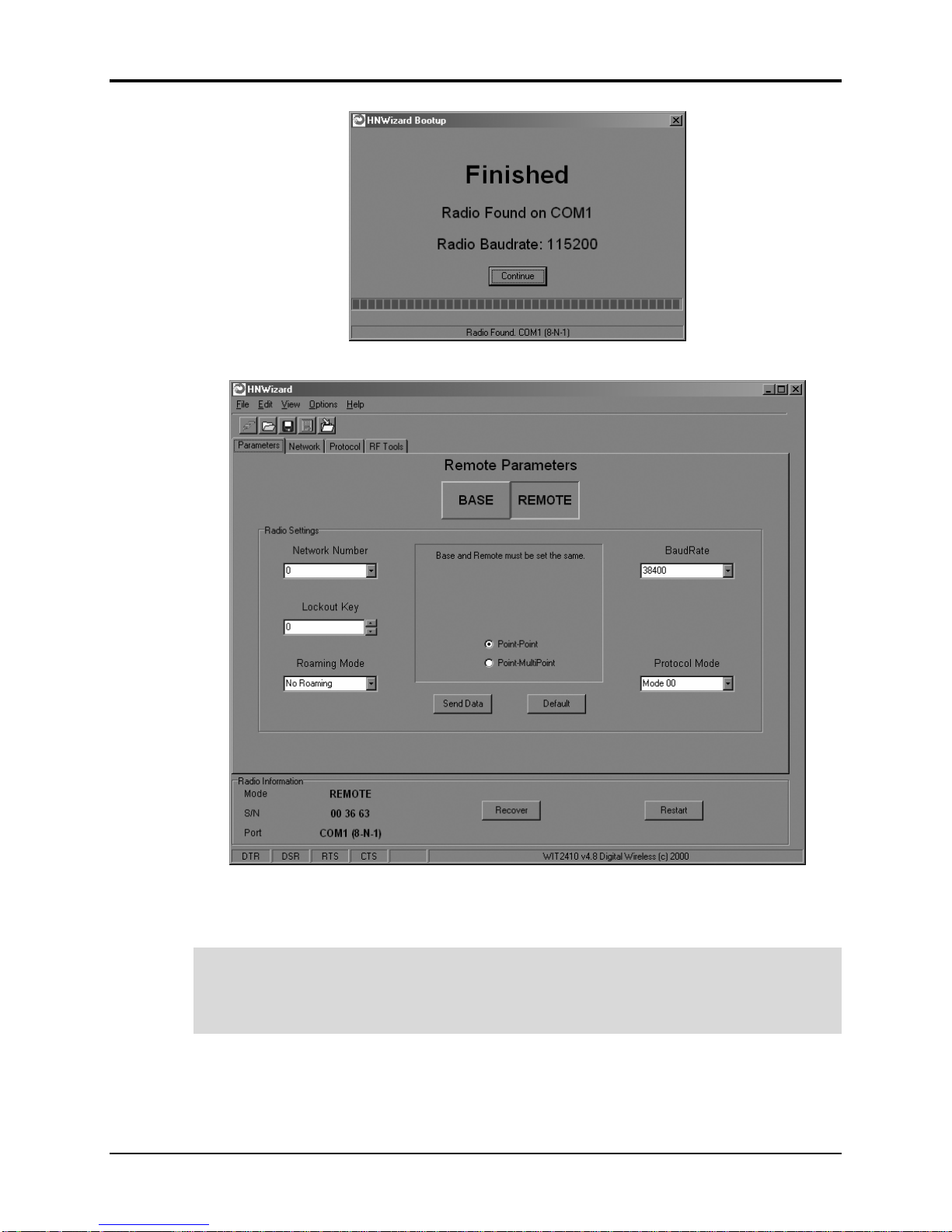
port the HopNet radio is connected to and its baud rate. When the radio has been
detected, the Continue button will appear.
©2000- 2004 Cirronet™Inc 5 M-2410-0022 Rev B
HopNet RS-232 Serial ModBus Radio
Click on the Continue button to bring up the next screen.
The program will read and display the current settings of the HopNet radio. The
HopNet radio is shipped from the factory as a remote. The Remote button on the
Wizard screen will appear depressed indicating the HopNet radio is a remote.
NOTE: The S/N displayed in the bottom left corner is the serial number of the
radio inside the unit and is different from the serial number of the HopNet unit.
Both the HopNet unit serial number and the radio serial number are on the radio
unit of the HopNet product.
To set the HopNet radio as a base, click on the Base button. The Base button will
depress and the Remote button will pop up. The screen heading will change from
“Remote Parameters” to “Base Parameters.”
©2000- 2004 Cirronet™Inc 6 M-2410-0022 Rev B
HopNet RS-232 Serial ModBus Radio
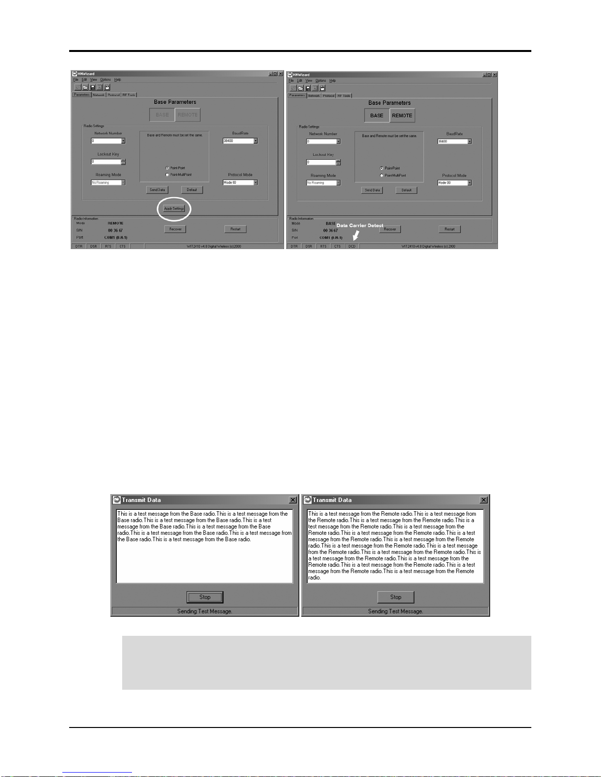
The Apply Settings button will appear at the bottom of the HopNet Configuration
Wizard screen. Click on the Apply Settings button to set the HopNet radio as the
base.
Run a communications test.
To run a communications test, connect one HopNet radio set as a base to one PC
running the Wizard and another HopNet radio set as a remote to another PC running
the Wizard. Verify that the Carrier Detect LED (CD) on the radio is on (red), the fifth
parameter box on the lower left of the window will have DCD (as shown above
right). Click on the Send Data button on the HopNet Configuration Wizard screen on
both PCs. The HopNet radio set up as the base will send the message “This is a test
message from the Base radio.” to the remote HopNet radio. This message will be
displayed in the message window of the Wizard running on the remote PC. The
remote HopNet radio will send the message “This is a test message from the Remote
radio.” to the base HopNet radio. This message will be displayed in the message
window of the Wizard running on the base PC. The test will run continuously until
the Stop button is clicked.
NOTE: If your computer has two serial ports, both the base and the remote HopNet
radios can be connected to the same PC and the communications test run by
opening a second window running the Wizard. Open the second window by simply
double-clicking on the Wizard icon on your desktop.
©2000- 2004 Cirronet™Inc 7 M-2410-0022 Rev B

HopNet RS-232 Serial ModBus Radio
The Serial Adapter Box
The HopNet radio remotes interface with the user’s hardware through a serial adapter
box. The interface adapter supplies power and signal to the remote unit. The
interface to the remote unit is a RS-232 male DB-9 serial interface. To have all
functions of the HopNet radio available, including configuration and hardware flow
control, the eight signal lines must be connected.
CONFIG Mode
When the RUN/CONFIG switch is in the CONFIG position, the HopNet radio data
connector is set up as a DCE device. This allows communication with a PC using the
straight-through, serial cable provided with the HopNet radio. The switch must be in
the CONFIG position to run the HN Wizard.
RUN Mode
When the RUN/CONFIG switch is in the RUN position, the HopNet radio data
connector is set up as a DTE device. The switch must be in the RUN position to
operate with a PLC configured as a DCE device.
3 Wire Operation
If configuration and hardware flow control is not necessary, the HopNet radio can be
used in 3-wire mode. In this mode, only Ground, Receive Data and Transmit data are
connected. The connector pinout is provided below.
©2000- 2004 Cirronet™Inc 8 M-2410-0022 Rev B

HopNet RS-232 Serial ModBus Radio
Remote Pin-Out, RS-232
Pin Number Signal Type Description
1 DCD Output Data Carrier Detect. For remotes, DCD indicates
that the remote has successfully acquired the
hopping pattern.
2 RXD
(CONFIG)
Output Output for Received Serial data.
2 TXD
(RUN)
Input Input Serial Data to be transmitted
3 TXD
(CONFIG)
Input Input Serial Data to be transmitted
3 RXD
(RUN)
Output Output for Received Serial data.
4 DTR Input Data Terminal Ready. Sleep/ wakes radio
transceiver.
5 GND - Signal and Chassis Ground
6 DSR Output Data Set Ready. Response to DTR.
7 RTS Input Request to Send. Gates the flow of receive data
from the radio to the user on or off. In normal
operation signal should be asserted.
8 CTS Output Clear to Send. Used to control transmit flow from
the user to the user to the radio. The WIT 2410
radio module supports hardware flow control
only and does not support software flow control
(e.g. Xon-Xoff).
9 Not Used - Not Used
NOTE: When the HopNet radios are used as three wire serial devices, DTR and RTS do not
have to be used.
©2000- 2004 Cirronet™Inc 9 M-2410-0022 Rev B

HopNet RS-232 Serial ModBus Radio
Guidelines for Installation
When installing your system, always consider the following points:
Directional antennas are best for remote unit sites. They may increase the cost, but
they confine the transmission path to a narrow lobe and minimize the interference
from nearby stations.
For systems with constant interference present, you may need to change the polarity
of the antenna system and reduce data streams. Groups of short data streams are more
reliable and have a better chance of success in the presence of interference than do
long data streams.
Systems installed in rural areas are least likely to encounter urban interference.
Multiple HopNet systems can operate in close proximity to each other but require a
unique network address.
Poor quality coaxial cables will seriously degrade system performance. Use low- loss
cable that is suitable for 2.4 GHz operation.
Short cable runs minimize signal loss.
Refer to the section Troubleshooting for additional information on installing a radio.
Aiming the Antenna and Placing the Remote
Use the following guidelines for aiming the antenna and placing the Remote;
•Do not place anything immediately in front of the antenna that could obstruct
its radiation pattern. Because the antenna in the HopNet Remote is inside the
unit, the antenna must have a clear line of sight.
NOTE: Use the sticker on the HopNet Remote unit to help you locate and aim the
antenna. The sticker indicates which direction the antenna is pointing.
•Be sure the antenna end of the HopNet radio Remote faces the Base or
Repeater that it is communicating with. Our tests have found that antenna
placement is not critical as long as the patch antenna is facing in the general
direction of the other end of the link.
•If possible, place the Remote unit at a higher elevation than the structures
surrounding it to increase range and link reliability. Since the Remote will
operate with up to 100 feet of interconnect cable between it and the Host, you
can mount the unit on top of a building or other structure that will provide
higher elevation.
Interconnect Cable
The HopNet radios come with 50’ (15 meters) of high quality interconnect cable.
The cable may be lengthened by adding an additional 50’ cable (part no.:
CBLEXT50). The maximum cable length that the HopNet radios will support is 100’
(30 meters).
©2000- 2004 Cirronet™Inc 10 M-2410-0022 Rev B

HopNet RS-232 Serial ModBus Radio
Configuring the Network
You can configure the HopNet network using a PC and the HopNet Configuration
Wizard software provided by Cirronet, Inc. The Wizard runs under Windows
98/NT/2000/XP. This chapter provides the information you need to configure your
network.
HopNet Configuration Wizard (5.0 or later)
If you haven’t already installed the Wizard program, refer to the Getting Started
section of this manual for instructions. Open the Wizard by double-clicking on the
icon on the desktop. When the Wizard boots up, it will automatically detect the serial
port to which the HopNet radio is connected and its baud rate. This process takes a
few seconds to complete. During this process, the “Please wait” screen is displayed.
Once the radio has been found and the Baudrate determined, the “Finished” screen is
displayed. Click on the Continue button to enter the Wizard.
NOTE: The HopNet configuration Wizard is used with a variety of Cirronet radios.
Not all radios support all the functions and features of every Cirronet radio. Thus,
some selections in the Wizard will be grayed out if they are not applicable to the
radio in use.
After detecting the serial port and baud rate of the HopNet radio, the Wizard reads the
settings of the HopNet radio that is connected to the PC and will display them in the
various parameter windows. In the bottom left corner of the Wizard window, the
Base/Remote status, the serial number and the communication port are always
displayed.
©2000- 2004 Cirronet™Inc 11 M-2410-0022 Rev B

HopNet RS-232 Serial ModBus Radio
NOTE: The S/N displayed in the bottom left corner is the serial number of the
radio inside the unit and is different from the serial number of the HopNet unit.
Both the HopNet unit serial number and the radio serial number are on the radio
unit of the HopNet product. The Wizard will also prompt to save the configuration
settings to a file.
When a parameter value is changed from the value currently in the HopNet radio, the
parameter label and value will turn red and the Apply Settings button will appear.
When the value is changed back to the value that is currently in the attached HopNet
radio, the label and parameter value will return back to black. When new values are
applied to the HopNet radio, the red values will turn black indicating the updated
values in the radio.
NOTE:The changes are not sent to the HopNet radio until the Apply Settings
button is clicked.
Context sensitive help is available through the F1 key or Help menu.
About the INIT.INI File
One of the files unpacked with the program is the INIT.INI file. It contains the entries
below and an explanation has been included on how each parameter may be used.
ErrorLevel=0
Leave this value as is. Only change it at the request of Cirronet Tech Support.
BiDirectionalHigh=55
BiDirectionalMedium=40
ReceiveHigh=55
ReceiveMedium=40
These parameters change the color levels (in percent) on the RF Tools bar
graphs/pie charts.
RFToolsInterval=1000
This parameter sets the how often bar graphs / pie charts will update (in msec)
RSSIMarginal=-60
RSSIPoor=-80
These parameters set the levels (in dBm) of color the bars on the RSSI bar chart
will display. Above the level set by RSSIMarginal, the bars will be green in
color. Between the levels set by RSSIMarginal and RSSIPoor, the bars will be
yellow in color and below the level set by RSSIPoor, the bars will be red in color.
FullShow=0, 1, 2
This changes the number of options that are viewable
0 (default) = Shows minimum amount of options.
1 = Adds all other options.
2 = Adds WinCom.
AutoDetect=1
1 = Auto-detects radio,
0 = User-defined inputs
The parameters below should not be changed as they are specific to different radios.
These parameters will come from the factory set for your radio.
©2000- 2004 Cirronet™Inc 12 M-2410-0022 Rev B

HopNet RS-232 Serial ModBus Radio
-40dBm=125
-95dBm=55
When the Wizard program is opened, it reads the parameters of the HopNet radio
connected to the PC. These initial parameters are stored by the Wizard until the
program is closed. This function allows the initial parameters to be loaded into any
HopNet radio that is connected to the PC. Clicking on the Recover button displays the
settings stored when the Wizard was first opened but will not load them in the radio
until the Apply Settings is clicked. When the Apply Settings button is clicked, all the
changed values will be loaded into the radio, even if the changed values are not on the
tab currently displayed.
Parameters Tab
The Wizard program opens the main screen with the Parameters Tab displayed. The
parameters screen of the Wizard allows the following variables to be set;
1. Base or Remote
2. Point-to-Point or Multipoint
3. Baud rate
4. Network number
5. Lockout Key
6. Roaming Mode
7. Protocol Mode
©2000- 2004 Cirronet™Inc 13 M-2410-0022 Rev B

HopNet RS-232 Serial ModBus Radio
Depending on whether HopNet radio is configured as a Remote or Base when first
connected, the heading on the Parameters page will display either “Remote
Parameters” or “Base Parameters.” If the radio has a Modbus adapter, Transparent,
Modbus and DNP3 selections will appear above the Point-Point-Multipoint selection
as shown below.
Modbus mode is selected to prevent Modbus errors from occurring due to inter-
character gaps that are too long. Refer to the section, Modbus Operation for details on
this mode.
Network Number
This parameter is also known as Set Hopping and is the same command as wn.(Refer
to “Configuration Commands” section for additional information on commands.) By
using different network numbers or “hopping patterns”, nearby or co-located
networks can avoid interfering with each other’s transmissions.
BaudRate
Also known as Set Data Rate Divisor (command sd) this parameter sets the serial bit
rate between the modem and the host.
©2000- 2004 Cirronet™Inc 14 M-2410-0022 Rev B
This manual suits for next models
5
Table of contents
Other Cirronet Radio manuals


Popular Radio manuals by other brands


Cobra Marine
Cobra Marine MARINE MR HH330 FLT EU owner's manual

Radio Shack
Radio Shack 1201479 user guide

Rassbach Communications
Rassbach Communications FreedomLINK installation instructions

Ericsson
Ericsson LBI-39014B Maintenance manual

Honeywell
Honeywell ISM BAND XYR 5000 LINE user guide

Lanzar
Lanzar VBD 1600MP owner's manual


