Cirronet ZN-241G Use and care manual

ZN-241G
802.15.4 Radio
Technical Reference
3079 Premiere Pkwy, Ste. 140
Duluth, Georgia 30097
www.cirronet.com
+1 67 6 4-2000

Important Regulatory Information
Cirronet Product FCC ID: HSW-ZN2 1
IC 92A-ZN2 1
FCC s MPE Requirements
Information to user/installer regarding FCC s Maximum Permissible Exposure (MPE) limits.
Notice to users/installers using the follo ing mobile antennas, ith Cirronet RF products:
ZN2 1 5 dBi and 2 dBi Omni Antennas
The field strength radiated by any one of these antennas, when connected to Cirronet RF products, may exceed FCC
mandated RF exposure limits. FCC rules require professional installation of these antennas in such a way that the
general public will not be closer than 20 cm from the radiating aperture of any of these antennas. nd users of these
systems must also be informed that RF exposure limits may be exceeded if personnel come closer than 20 cm to the
apertures of any of these antennas.
Approved Antennas
5 dBi Collinear – Nearson Antennas
Colinear
Colinear
5 dBi
5 dBi
7"
7"
SMA
SMA
R/A
Swivel
Nearson
Server
<<<<<
S-151AH-2450S
Client
>>>>>
S-151FL-36-AH-
2450
Right Angle Straight
Swivel
Note: This unit has been tested and found to comply with the li
mits for a Class A digital device, pursuant to
part 15 of the FCC Rules. These limits are designed to provide reasonable protection against harmful
interference when the equipment is operated in a commercial environment. This equipment generates,
uses, a
nd can radiate radio frequency energy and, if not installed and used in accordance with the
instruction manual, may cause harmful interference to radio communications. Operation of this equipment
in a residential area is likely to cause harmful interferen
ce in which case the user will be required to correct
the interference at their expense.

Table of Contents
1. Getting Started........................................................................................................................2
1.1 Changing the Ba d Rate................................................................................... 2
1.2 Other Select Comm Port Settings ..................................................................... 2
2. Firmware Req irements.........................................................................................................3
2.1 Addressing ........................................................................................................ 3
2.2 Protocol Modes ................................................................................................. 3
3. Serial Protocol........................................................................................................................4
4. ZN-241G Commands.............................................................................................................5
4.1. ZN-241G Registers .......................................................................................... 7
4.2 ZN-241G Config ration Examples .................................................................. 12
5. ZN Wizard............................................................................................................................16
6. Freq ency Selection ............................................................................................................20
7. Specifications:......................................................................................................................23
8. Hardware Req irements ......................................................................................................24
9. Warranty ..............................................................................................................................25
ZN-2 1G Technical Reference
2000- 2006 Cirronet
Inc 2 M-2 00-0006 Rev A
1. Getting Started
The ZN-241G is designed to connect to another 802.15.4 radio. In almost all cases, if
you turn two ZN-241Gs on in range of each other, they will link to each other. The
simplest method for using two ZN-241Gs is to attach the antennas, power them both
up and then check the link lights (center red L D) on both radios. If they are both lit,
and the default baud rate of 38,400 is acceptable, no further configuration is needed.
The radios can be used as is.
1.1 Changing the Baud Rate
The ZNWizard software simplifies the configuration of several radio parameters, the
most basic being setting a baud rate other than the default. To change the baud rate,
connect the ZN-241G to a PC by plugging in the serial cable to the 9 pin connector on
the radio then connecting the other end to the serial port on the PC. Plug the
transformer end of the power supply into a wall outlet and the other end into the ZN-
241G and launch the ZNWizard software; the following screen will appear.
Select a different baud rate using the drop down menu labeled Baudrate then Click
OK; the following screen will display. Close down ZN Wizard and connect the other
ZN-241G up in the manner described above and repeat the procedure for the second
radio, then click OK. The radios are now ready for use.
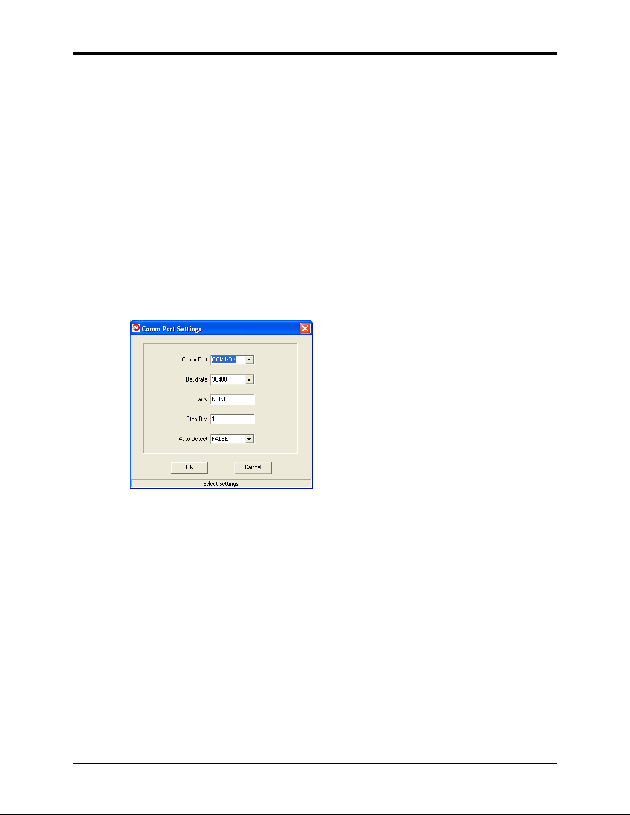
1.2 Other Select Comm Port Settings
In addition to changing the baud rate, you may also change the Comm Port, Parity,
Stop Bits and whether or not Auto Detect is needed. Default values for these
parameters are displayed in the window above. Available Comm Ports will be marked
with an “OK”; others will be marked with ‘N/A”. The Auto Detect function works
this way. If set to FALS , once OK is selected, the program uses the default settings
to search for the radio. If set to TRU , the program will begin a systematic process
beginning with the first valid port (COM 1 in most cases) then will cycle through
each baud rate, then each parity setting, then each stop bit setting finally changing to
the next available COM port and repeating the process until a radio is found.

ZN-2 1G Technical Reference
2000- 2006 Cirronet
Inc 3 M-2 00-0006 Rev A
2. Firmware Requirements
The radio supports protocol-based messaging with one-hop mesh routing capability
for transmissions between the base and a remote (in either direction). Peer-to-peer
messaging is not officially supported, but should work for limited applications. The
ZN-241G will support transparent messaging in addition to protocol-based service.
2.1 Addressing
The ZN-241G uses 8-bit network addresses, which are assigned by the base. ach
radio also carries a factory-set 64-bit MAC address. When a remote connects to the
base for the first time, the base assigns a network address (NWK) between 01 and 60
(decimal) for that MAC address and records it in an PROM table so that the same
address is assigned if the devices are power-cycled. Under normal operation, it is
required that no more than 60 remotes connect to a base. If this limit is exceeded, the
table will be automatically cleared and all network addresses reassigned on a first-
come, first-serve basis.
There are two special reserved network addresses. The base has NWK address of
0x00
, and
0xFF
is used to indicate a broadcast packet.
2.2 Protocol Modes
The ZN-241G can be used in either transparent or protocol-based applications. By
default, the radio is configured at startup to operate in transparent multipoint mode.
To change settings, the user must enable protocol mode. This is accomplished by
sending the EnterProtocolMode command as the first string delivered to the
radio after power-up. In order to be accepted, the command must be entered
contiguously with no space between characters of more than
TransparentModeTimeout (default = 5 ms); otherwise, the packet will be
treated as transparent data instead of a command and sent over-the-air.
The ZN-241G configuration is stored in a set of variable length registers. Most can
be both read from and written to, but some are read-only. Changes made by the user
to the register settings are temporary until a SaveSettings command is executed.
Resetting the radio or power-cycling will clear any changes that have not been saved
to permanent memory using the SaveSettings command.
The ZN-241G may be configured to start in protocol mode at power-up, in which
case the EnterProtocolMode command is not required.

ZN-2 1G Technical Reference
2000- 2006 Cirronet
Inc M-2 00-0006 Rev A
3. Serial Protocol
All of the packets in the ZN-241G serial protocol have a common header format:
1 byte 1 byte 1 byte 1 byte Varies
SOP
(0xFB)
Length
(in bytes)
TransID
MSG
Type Arguments
The start-of-packet (SOP) character, 0xFB, is used to distinguish the beginning of a
packet and to assure synchronization in the event of a startup glitch on the serial port
at startup.
The Length byte is defined as the length of the remainder of the packet following the
length byte itself (or the length of the entire packet - 2).
The message type (MSGType) identifier specifies the type of command or reply
packet. Based on this value, as well as various packet options which allow the rest of
the packet to be decoded. It is a bitfield-oriented specifier, decoded as follows:
Bit 7-5 -- Reserved for future use.
Bits 4 -- Reply. Indicates this packet is a reply.
Bits 3:0 – Type. Indicates the packet type/command.
As indicated, the lower 4 bits (3:0) specify a packet type or command specifier. Bit 4
is a modifier indicating that the packet is a reply to a previously received packet. The
reply packet always has the original command type as bits 3:0, with bit 4 set to one.
The Transaction ID (TransID) is provided as an identifier to help a host device
distinguish replies from multiple commands that may be in process. It is currently
expected that the module will always reply to commands in the order they are
received, but this may not always be the rule in future extensions to the protocol.
Transaction IDs for commands and replies are paired -- the reply will match the
command. Since event packets are not generated in response to a command, a
separate transaction ID counter is maintained by the radio for events, and is initialized
to
0x00
at startup.
Arguments are packet-specific fields. These vary in size and number depending on
the type of packet and whether it is a packet sent from the user or reply from the
radio; see the tables in Section 4 for more information.
Packets that are generated on the serial interface by the user are referred to as "host"
packets. Packets that are generated by the radio are referred to as "reply" packets.
For many packet types, there is a reply packet that corresponds to a host packet; e.g.,
when the host sends a TxData packet, the radio will reply to indicate the status of
the transmission, whether it succeeded or failed. Some packet types are host-only or
reply-only.

ZN-2 1G Technical Reference
2000- 2006 Cirronet
Inc 5 M-2 00-0006 Rev A
. ZN-2 1G Commands
ach ZN-241G command generally has two forms, a command from the host and a
reply from the radio. Depending on the direction, they have different arguments as
shown in the table below. Unsolicited events from the radio such as receive data
packets or status announcements make up a third category of packets.
To assist in interpreting the data flow, the direction is indicated by the high nybble of
the packet type -- e.g., an EnterProtocolMode command from the host is packet
type
0x00
, and the EnterProtocolMode reply from the radio is packet type
0x10
.
vents, such as Announce packets or RxData packets are indicated by
0x20
in the
high nybble. If multiple arguments are to be provided, they are to be concatenated in
the order shown. Little-endian byte format is used for all multi-byte arguments.
Packet Type
CMD Reply
Event
Description Direction Arguments
0x00 EnterProtocolMode from Host ZN-241G”
0x10 EnterProtocolModeReply from Radio none
0x01 ExitProtocolMode from Host none
0x11 ExitProtocolModeReply from Radio none
0x02 SoftwareReset from Host none
0x12 SoftwareResetReply from Radio none
0x0 GetRegister from Host Reg
0x1 GetRegisterReply from Radio Reg,Val
0x04 SetRegister from Host Reg,Val
0x14 SetRegisterReply from Radio none
0x05 TxData from Host Addr,Data
0x15 TxDataReply from Radio TxStatus,LQI
0x26 RxData from Radio Addr,LQI,Data
0x27 Announce from Radio AnnStatus,add’l fields

ZN-2 1G Technical Reference
2000- 2006 Cirronet
Inc 6 M-2 00-0006 Rev A
Arguments:
Reg Register location (see table) (2 bytes)
Val Val e to read/write to/from register
(see table for size and acceptable range)
Data User data (variable size, 0..100 bytes permitted)
Addr Network address of sender or recipient (1 byte)
TxStatus Res lt of last
TXData
operation (1 byte)
0 = Acknowledgement received
1 = No acknowledgement received
2 = (Remote) Not linked
LQI Link q ality index, 0x01 to 0x7F. Val es of 0x00 and 0xFF have
special meanings (1 byte)
00 = No LQI meas red beca se no ACK was received
FF = No LQI meas red beca se packet was relayed
PanID 802.15.4 PAN identifier of network joined (2 bytes)
SerNum Serial n mber of radio joining (also sed as 802.15.4 MAC address) (8
bytes)
AnnStatus Stat s anno ncement (1 byte)
Additional fields are also reported depending on the stat s code:
Stat s Code
A0 = Radio has completed start p initialization
A1 = Base: PAN has been formed, ready for data
A2 = Base: A remote has joined o r PAN
A = Remote: Joined a PAN, ready for data
A4 = Remote: Exited PAN (base is o t of range)
A5 = Remote: Base has restarted
Add’l fields
none
PanID
SerNum,Addr
PanID,Addr
none
none
Stat s codes for error conditions
E0 = Protocol error – invalid packet type
E1 = Protocol error – invalid arg ment
E2 = Protocol error – parser error
E = Protocol error – parser timeo t
E4 = Protocol error – register is read-only
E8 = UART receive b ffer overflow
Add’l fields
none
none
none
none
none
none

ZN-2 1G Technical Reference
2000- 2006 Cirronet
Inc 7 M-2 00-0006 Rev A
.1. ZN-2 1G Registers
Location Name R/W Size Range Defa lt
0x0000 DeviceMode R/W 1 0..1 0 = Remote, 1 = Base
0x0001 SerialRate R/W 1 0..255 38400 bps (0x19)
0x0002 SerialParams R/W 1 0..7 n,8,1 (0x00)
0x000 ProtocolMode R/W 1 0..3 0 = trans/pt-pt with a to-match
1 = trans/pt-pt
2 = trans/m lti
3 = protocol
0x0004 PanID R/W 2 0x0001
0x0005 ChannelMask R/W 4 All b t 2480MHz
0x0006 C rrPanID R 2 00-FFFF
0x0007 C rrChannel R 1 0..15
0x0008 C rrNwkAddress R 1 0..62
0x0009 MacAddress R 8
0x000A TxAttemptLimit R/W 1 0..16 5 attempts
0x000B TxTimeo t R/W 1 0..255 5 ms
0x000C A toRelayEnable R/W 1 0..1 1 (enabled)
0x000D HardwareVersion R 1 0-F
0x000E FirmwareVersion R 1 0-F
Upper nybble is first digit; lower
nybble is second digit.
Ex: 1100 0110
F(12) 6= ver. 12.6
0x000F LinkStat s R 1 0..1 1 = linked
0x0010 TransLinkAnnEn R 1 0..1 0 = defa lt, 1 = “LINK” anno nce
0xFFFF MemorySave W 1 Write 0x00 to load factory defa lts (“MO”)
Write 0x01 to save settings to EEPROM (M>”)

ZN-2 1G Technical Reference
2000- 2006 Cirronet
Inc 8 M-2 00-0006 Rev A
DeviceMode
Sets the mode of the radio. 0=Remote (default), 1=Base. There can be only one base
radio for the network.
Baudrate
Sets the rate divisor of the serial port. The baud rate is given by
BAUD = 1e6 / (SerialRate+1)
The following are recommended Baudrate settings for common baud rates:
Setting Nominal Actual Error
0x67 "9600" 9615 +0.2%
0x33 "19200" 19231 +0.2%
0x19 "38400" 38460 +0.2%
0x10 "57600" 58824 +2.1%
0x08 "115200" 111111 -3.7%
Note that these rates are approximate, not exact. Note that because the ZN-241G is -
3.7% slow at the 115200 bps rate, the host device *must* be configured for 2 stop
bits to use this rate! Likewise, at 57600, it may be necessary in some applications to
configure the ZN-241G for 2 stop bits to avoid overrunning the host.
SerialParams
Sets the operating parameters of the serial port. The following modes are supported:
Setting Mode
0x00 No parity, 8 data bits, 1 stop bit
0x01 No parity, 8 data bits, 2 stop bit
0x02-0 reserved
0x04 Even parity, 8 data bits, 1 stop bit
0x05 Even parity, 8 data bits, 2 stop bit
0x06 Odd parity, 8 data bits, 1 stop bit
0x07 Odd parity, 8 data bits, 2 stop bit
ProtocolMode
nables or disables use of the radio's host protocol.
0
= transparent / point-to-point / ACK / with A to-Match (defa lt)
1
= transparent / point-to-point / ACK
2
= transparent / m ltipoint / no-ACK
3
= protocol / m ltipoint / ACK

ZN-2 1G Technical Reference
2000- 2006 Cirronet
Inc 9 M-2 00-0006 Rev A
In transparent modes, the radio will accumulate bytes until either it reaches a
maximum size of 109 bytes, or there is a gap in the data longer than the
TxTimeout. The difference between the ACK and no-ACK modes is that if ACKs
are enabled, the radio will send the message and wait for a response from the intended
recipient. If none is received, it will resend the message up to TxAttemptLimit
times. When finished, the radio will output a TX_DATA_R PLY packet to indicate
the result to the host. In no-ACK mode, each datagram is sent over the air only once,
there is no acknowledgement, and there is no TX_DATA_R PLY notification.
Auto-Config mode, which is the default, is intended to allow a pair of units to
communicate with each other right out of the box without any configuration by the
user. When configured for Auto-Config, a radio will alternate between base and
remote modes approximately every 4 seconds attempting to link with another radio.
If the link is broken, either due to one radio powering off or going out of range, the
Auto-Config process will resume toggling the device mode until a link is recovered.
In protocol mode, the maximum allowable packet size is 109 bytes (payload bytes),
or a length value of 112.
PanID
Sets the radio's PAN identifier. Radios must have the same PAN identifier in order
for them to link or exchange data. A remote may be given a PanID of 0xFFFF,
which instructs it to take the PAN ID of the first base it finds. In this case, the
CurrPanID register may be used to read back the ID of the PAN selected.
ChannelMask
Sets the list of channels that the radio is allowed to choose from. (See Section 7 -
Frequency Selection.) For a base radio, it is generally recommended that one channel
be selected in the mask. This gives it a known channel for frequency planning
purposes. If more than one channel is enabled, the base will pick one of them at
random at startup, and not switch from it unless the radio is reset or power-cycled.
For a remote radio, the channel mask specifies which channels it will look for a base
on. For greatest flexibility, it is useful to set a remote for all channels, so that the
remotes need not all be reconfigured if it is necessary to reassign the base to a new
frequency. For a slightly faster link time, set the remote's mask to a single channel.
If a remote loses link, is reset, or is power-cycled, it will rescan all of the channels in
its mask continually until its base is found.
CurrPanID
Used to read back the radio's current PAN identifier. For use with remotes that have
been set with PanID =
0xFFFF
.

ZN-2 1G Technical Reference
2000- 2006 Cirronet
Inc 10 M-2 00-0006 Rev A
CurrNwkAddress
Used to read back the radio's current network address. This is a number between
0x00
and
0x D
(61decimal). The base is always address 0. Remotes will report
0xFF
if they have not yet linked with a base. Base radios store network addresses they
have assigned to remotes in PROM, so a remote should get the same address each
time it connects. There is a limit of 61 remote addresses that the base can store,
however, and if this limit is reached, the base clears its table and reboots to ensure
that all remotes are forced to disconnect and reattach.
CurrMacAddress
Used to read back the radio's unique factory-set MAC address.
TxAttemptLimit
The maximum number of times a radio will attempt to send a data packet if no ACK
is received. See ProtocolMode for more details. Default is 5 attempts
TxTimeout
In transparent mode, the maximum gap between data bytes before a message will be
gathered from the buffer and sent over the air. Units are milliseconds. Default is 5
milliseconds. See ProtocolMode
for more details
.
AutoRelayEnable
nables the auto-relay messaging feature of the ZN-241G. This allows a transmitting
radio which has not been acknowledged by its recipient to relay its message to
another radio to retransmit on its behalf.
HardwareVersion
This returns a 2-digit BCD identifier indicating the hardware version the radio is
running on.
FirmwareVersion
This returns a 2-digit BCD identifier indicating the firmware version the radio is
running.
LinkStatus
Indicates whether radio is ready to send data. '0' = unlinked, '1' = linked.

ZN-2 1G Technical Reference
2000- 2006 Cirronet
Inc 11 M-2 00-0006 Rev A
TransLinkAnnEn
In transparent mode, other than the L D, there is no direct means of determining
whether or not a radio is linked. Setting this field to a one will cause the radio to send
the string "LINK" to the host, either in the case of a remote whenever it successfully
associates with a base, and in the case of a base whenever a remote successfully
associates with it. Disabled by default.
MemorySave
Writing a zero to this location clears all registers back to factory defaults. Writing a
one to this location commits the current register settings to PROM. When
programming registers, all changes are considered temporary until this command is
executed
.

ZN-2 1G Technical Reference
2000- 2006 Cirronet
Inc 12 M-2 00-0006 Rev A
.2 ZN-2 1G Configuration Examples
Some example commands and replies are listed below.
xample 1: Configure a remote to switch from transparent mode to protocol mode,
set the PAN ID and channel mask, save the new settings, and restart so that they take
effect. After connection with the base, send a message to the base and receive a
response.
Enter Protocol Mode
Host Packet
FB 08 00 00 ZN-241G
SOP
(0XFB)
Length
(in bytes)
TransID
MSG
Type Arguments
Reply Packet
FB 02 00 10
SOP
(0XFB)
Length
(in bytes)
TransID
MSG
Type Arguments
Set Register - PAN ID =
0xE701
Host Packet
FB 06 01 04 04 00 01 E7
SOP
(0XFB)
Length
(in bytes)
TransID
MSG
Type Arguments
Reply Packet
FB 02 01 14
SOP
(0xFB)
Length
(in bytes)
TransID
MSG
Type Arguments
ZN-2 1G Technical Reference
2000- 2006 Cirronet
Inc 13 M-2 00-0006 Rev A
Set Register - Channel Mask = 2 0 MHz only
Host Packet
FB 08 02 04 05 00 00 00 04 00
SOP
(0xFB)
Length
(in bytes)
TransID
MSG
Type Arguments
Reply Packet
FB 02 02 14
SOP
(0xFB)
Length
(in bytes)
TransID
MSG
Type Arguments
Set Register - Protocol Mode = mode 3 (protocol enabled)
Host Packet
FB 05 03 04 03 00 03
SOP
(0xFB)
Length
(in bytes)
TransID
MSG
Type Arguments
Reply Packet
FB 02 03 14
SOP
(0xFB)
Length
(in bytes)
TransID
MSG
Type Arguments
Set Register - Save changes to EEPROM
Host Packet
FB 08 04 04 FF FF
SOP
(0xFB)
Length
(in bytes)
TransID
MSG
Type Arguments
Reply Packet
FB 02 04 14
SOP
(0xFB)
Length
(in bytes)
TransID
MSG
Type Arguments

ZN-2 1G Technical Reference
2000- 2006 Cirronet
Inc 1 M-2 00-0006 Rev A
Reset Radio
Host Packet
FB 02 00 00
SOP
(0xFB)
Length
(in bytes)
TransID
MSG
Type Arguments
Reply Packet
FB 02 00 10
SOP
(0xFB)
Length
(in bytes)
TransID
MSG
Type Arguments
Status Announce - Initialization complete
Reply Packet
FB 03 01 17 00
SOP
(0xFB)
Length
(in bytes)
TransID
MSG
Type Arguments
Status Announce - Joined PAN
Reply Packet
FB 03 02 17 04
SOP
(0xFB)
Length
(in bytes)
TransID
MSG
Type Arguments
Transmit Data (to base, address
0x0000
)
Host Packet
FB 0B 03 05 00 00 54 65 73 74 69 6E 67
SOP
(0xFB)
Length
(in bytes)
TransID
MSG
Type Arguments
Reply Packet
FB 02 03 15 00 C4
SOP
(0xFB)
Length
(in bytes)
TransID
MSG
Type Arguments

ZN-2 1G Technical Reference
2000- 2006 Cirronet
Inc 15 M-2 00-0006 Rev A
Receive Data (from base, address
0x0000
)
Reply Packet
FB 13 04 15 00 00 C2 4D 65 73 73 61 67 65 20 72 65
63 65 69 76 65 6D
SOP
(0xFB)
Length
(in bytes)
TransID
MSG
Type Arguments

ZN-2 1G Technical Reference
2000- 2006 Cirronet
Inc 16 M-2 00-0006 Rev A
5. ZN Wizard
ZNWizard can be found on the Software and Documentation CD. Double click on
znwizard.exe and the following screen will appear.
Click on Connect and the Select Comm Port Settings dialog will display as shown
below. This dialog allows for changing configuration parameters for the Comm Port,
Baudrate, Parity, Stop Bits and Auto-Detect.
If all the default settings are suitable, click OK and the software will go out and find
the ZN-241G. If there is a problem with the default settings, use the drop-down
menus to make changes. For a more detailed description of these parameters, refer to
the individual descriptions at the end of this section.

ZN-2 1G Technical Reference
2000- 2006 Cirronet
Inc 17 M-2 00-0006 Rev A
Once a ZN-241G is found, the following screen will display.
Notice that the “Status” in the lower left hand corner of the screen says “NOT
linked”. If another ZN-241G cannot be found, the program will continue to
periodically attempt to find and link with another ZN-241G. During that time, the
Status Window will continue to display information regarding the search.
Once another radio has been found and linked to, the “Status” in the lower left hand
corner will change to LINK D and the Current Settings window will update as
shown below.

ZN-2 1G Technical Reference
2000- 2006 Cirronet
Inc 18 M-2 00-0006 Rev A
In addition to changing the baud rate, ZN Wizard allows you to modify many other
parameters in the ZN-241G radio. In the center of the dialog window is a box labeled,
“Network Settings”. The first drop down menu is labeled “Network” as shown below.
The four choices are, Auto-Config, Point-to-
Point, Broadcast and Packet. For a more
detailed description of these parameters, refer
to Section 4.1
Device Mode sets the mode of the radio to
either Remote (default) or Base. There can be
only one base radio for the network.
This sets the Network identifier. Radios must
have the same network identifier in order for
them to link and exchange data.
In transparent mode, the maximum gap
between data bytes before a message will be
gathered from the buffer and sent over the air.
Units are milliseconds and the default is 5 ms.
The maximum number of times a radio will
attempt to send a data packet if no ACK is
received. Default is 5 attempts.
Other manuals for ZN-241G
1
This manual suits for next models
1
Table of contents
Other Cirronet Radio manuals


