CIRRUS DESIGN CAPS User manual

CIRRUS AIRFRAME PARACHUTE SYSTEM
MAINTENANCE MANUAL with ILLUSTRATED PARTS LIST
For the
CIRRUS DESIGN SR Series Airplane
CIRRUS DESIGN INCORPORATED
4515 Taylor Circle
Duluth, MN 55811
FAA APPROVAL HAS BEEN OBTAINED ON THE TECHNICAL DATA IN THIS PUBLICATION THAT AFFECTS AIRPLANE TYPE DESIGN.
COPYRIGHT 2002 CIRRUS DESIGN CORPORATION DULUTH, MINNESOTA, USA
P/N 12128-001
ISSUED SEPT, 2002
Procedures and parts listed in this manual are reflective of Cirrus Design SR20 airplanes serial numbers 1195 and subsequent, SR22 airplanes serial numbers 0210 and
subsequent, and all prior airplanes incorporating Service Bulletin SB 20-95-05 or SB 22-95-05 respectively.


12128-001 95-RevLog Page 1
Log of Revisions
Revision
Number
Issue
Date
Date
Inserted
Inserted
By
Revision
Number
Issue
Date
Date
Inserted
Inserted
By
15 Sept 2002


12128-001 95-LOEP Page 1
CHAPTER 95 - CIRRUS AIRFRAME PARACHUTE SYSTEM
LIST OF EFFECTIVE PAGES
Chapter/Section Page Date
95-REVLOG 1 15 SEPT 2002
95-LOEP 1 15 SEPT 2002
95-LOEP 2 15 SEPT 2002
95-TOC 1 15 SEPT 2002
95-TOC 2 15 SEPT 2002
95-01 1 15 SEPT 2002
95-01 2 15 SEPT 2002
95-01 3 15 SEPT 2002
95-01 4 15 SEPT 2002
95-01 5 15 SEPT 2002
95-01 6 15 SEPT 2002
95-01 7 15 SEPT 2002
95-01 8 15 SEPT 2002
95-01 9 15 SEPT 2002
95-01 11 15 SEPT 2002
95-01 12 15 SEPT 2002
95-01 13 15 SEPT 2002
95-01 14 15 SEPT 2002
95-01 15 15 SEPT 2002
95-01 16 15 SEPT 2002
95-01 17 15 SEPT 2002
95-01 18 15 SEPT 2002
95-01 19 15 SEPT 2002
95-01 20 15 SEPT 2002
95-01 21 15 SEPT 2002
95-01 22 15 SEPT 2002
95-01 23 15 SEPT 2002
95-01 24 15 SEPT 2002
95-01 25 15 SEPT 2002
95-01 26 15 SEPT 2002
95-01 27 15 SEPT 2002
95-01 28 15 SEPT 2002
95-01 29 15 SEPT 2002
95-01 30 15 SEPT 2002
95-01 31 15 SEPT 2002
95-01 33 15 SEPT 2002
95-01 34 15 SEPT 2002
95-01 35 15 SEPT 2002
15 Sept 2002


12128-001 95-TOC Page 1
CHAPTER 95 - CIRRUS AIRFRAME PARACHUTE SYSTEM
TABLE OF CONTENTS
Subject Chapter/Section Page
INTRODUCTION 95-01 1
Purpose 1
Using the CAPS Component Manual 1
Page Numbering System 1
Warnings, Cautions, and Notes 1
General 2
Description and operation 2
Activation System 4
Solid Propellant Rocket Motor Assembly 4
Rocket Igniter 4
Rocket Motor 4
Incremental Bridle and Deployment Bag 6
Parachute Assembly 6
Canopy and Suspension Lines 6
Slider 8
Airplane Attachment Harness 8
MAINTENANCE GUIDE 95-01 11
General 11
Servicing - Cirrus Airframe Parachute System 11
Removal - Pyrotechnic Line Cutters Replacement 11
Installation - Pyrotechnic Line Cutters Replacement 12
CAPS Cover 15
Removal - CAPS Cover 15
Installation - CAPS Cover 15
CAPS Rocket Assembly 20
Removal - CAPS Rocket Assembly 20
Disassembly - CAPS Rocket Assembly 20
Reassembly - CAPS Rocket Assembly 20
Installation - CAPS Rocket Assembly 21
CAPS Parachute Assembly 24
Removal - CAPS Parachute Assembly 24
Installation - Caps Parachute Assembly 24
Caps Activation Handle and Cable Assembly 25
Removal - Caps Activation Handle and Cable Assembly 25
Installation - Caps Activation Handle and Cable Assembly 26
Operational Check - Caps Activation Handle and Cable Assembly 27
15 Sept 2002


12128-001 95-01 Page 115 Sept 2002
INTRODUCTION
1. PURPOSE
The purpose of the Cirrus Design CAPS Maintenance Guide with Illustrated Parts List (CAPS Component
Manual) is to provide shop verified procedures that will enable an authorized CAPS technician to restore
the system to a functional condition. Procedures and parts listed in this manual are reflective of Cirrus
Design SR20 airplanes serial numbers 1195 and subsequent, SR22 airplanes serial numbers 0210 and
subsequent, and all prior airplanes incorporating Service Bulletin SB 20-95-05 or SB 22-95-05 respec-
tively. These procedures are prepared for authorized Cirrus Design CAPS technicians only.
Note: CAPS must be serviced and maintained by Cirrus Design trained and authorized parachute
system technicians only. Airframe and Powerplant license is not sufficient credentials for per-
forming maintenance on CAPS.
This manual was prepared using GAMA Specification #2 (Specification for Manufacturers Maintenance
data), Revised September 1982 as a content model and format guide. However, as the specification is writ-
ten to cover a whole class of aircraft rather than a particular model, some deviations from the specification
were made for clarity.
2. USING THE CAPS COMPONENT MANUAL
This CAPS Component Manual is divided into two major sections; the CAPS Maintenance Guide which
outlines approved maintenance practices, and the CAPS Illustrated Parts List, prepared to aid technicians
in identifying and procuring replacement parts.
A. Page Numbering System
Page numbers used in this manual consist of two-element numbers separated by dashes, under which
the page number and date are printed.
The chapter/system number corresponds to the GAMA Specification #2 system title. The second two-
element number is assigned by Cirrus Design and denotes the issue number of the respective chapter
title.
First Element Second Element
Chapter Issue
XX - XX
B. Warnings, Cautions, and Notes
Warnings, Cautions, and Notes are used to highlight or emphasize important points.
WARNING: Warnings call attention to use of materials, processes, methods, procedures, or
limits which must be followed precisely to avoid bodily injury.
CAUTION: Cautions call attention to methods and procedures which must be followed to avoid
damage to equipment.
Note: Notes call attention to methods which make the procedure easier.

12128-001
95-01
Page 2 15 Sept 2002
3. GENERAL
The airplane is equipped with a Cirrus Airplane Parachute System (CAPS) designed to bring the aircraft
and its occupants to the ground in the event of a life-threatening emergency.
CAPS consists of a parachute, a solid-propellant rocket to deploy the parachute, a rocket activation sys-
tem, and a harness imbedded within the fuselage structure.
A composite enclosure containing the parachute and solid-propellant rocket is mounted to the airplane
structure immediately aft of the baggage compartment bulkhead. The enclosure is covered and protected
from the elements by a thin composite cover.
The parachute is enclosed within a deployment bag that stages the deployment and inflation sequence.
The deployment bag creates an orderly deployment process by allowing the canopy to inflate only after the
rocket motor has pulled the parachute lines taut.
The parachute itself is a 2400-square-foot round canopy equipped with a slider, an annular-shaped fabric
panel with a diameter significantly less than the open diameter of the canopy. The canopy suspension lines
are routed through grommets so that the slider is free to move along the suspension lines. Since the slider
is positioned at the top of the suspension lines near the canopy, at the beginning of the deployment
sequence, the slider limits the initial diameter of the parachute and the rate at which the parachute inflates.
The canopy inflates as the slider moves down the suspension lines.
A three-point attachment harness connects the airplane to the parachute. The harness consists of two for-
ward straps faired into the fuselage skin and attached to the firewall, and one rear strap attached to FS 222
bulkhead located directly forward of the CAPS enclosure. The harness system is designed to control the
pitch dynamics of the airplane during the deployment cycle by limiting the aft attachment strap’s length until
the cycle is complete. This is accomplished by utilizing a variable length strap section. The shorter section,
which initially supports the load, employes a mechanical release that is activated by two pyrotechnic cut-
ters which fire when the short section is pulled taut during extraction. The harness strap then lengthens
and load is transferred to the longer section.
4. DESCRIPTION AND OPERATION (SEE FIGURE 95-011)
Two separate and deliberate pilot actions are required to deploy the CAPS parachute. The first action
requires the pilot to remove the access cover from the activation handle enclosure. The second action
requires the pilot to pull the activation handle out, and down several inches.
Upon pulling the activation handle, the activation cable compresses the igniter’s steel spring, cocks the
plunger and the following sequence is initiated: When one half-inch of plunger travel is reached, captured
ball-bearings are released allowing the plunger to strike the firing pins. The firing pins strike two primers
which ignite the primary booster. The primary booster ignites a secondary booster ensuring ignition of the
larger rocket motor. Once ignited, the rocket propellant’s hot gases are exhausted through the nozzle and
the rocket bursts through the CAPS enclosure cover pulling the deployment bag from the enclosure. The
deployment bag then stages the suspension line deployment and inflation of the parachute. As the para-
chute inflates, the forward harness assembly grows taut, pulls free of the fuselage skin, and stops at the
firewall compression tube which supports the forward portion of the airplane. The rear harness’ shorter
section is pulled taut, initiates the pyrotechnic line cutters which sever the shorter lines, and allow the
longer harness section to support the aft load. The airplane then assumes its touchdown attitude; approxi-
mately ten degrees nose down, to optimize occupant protection.

12128-001 95-01 Page 3
Figure 95-011
CAPS System and Deployment
15 Sept 2002

12128-001
95-01
Page 4 15 Sept 2002
A. Activation System (See Figure 95-012)
The rocket motor is activated by pulling an activation handle mounted in a recessed enclosure located
in the headliner above the pilot/copilot. This handle is connected to the rocket motor igniter with a flex-
ible, stainless steel aircraft grade cable routed through a cable housing above the cabin ceiling head-
liner.
A cover/placard is attached to the perimeter of the activation handle enclosure to prevent the handle
from being pulled accidentally. The placard identifies the system, presents the actions required to
deploy it, defines its operating envelope, provides appropriate warnings, and references the airplane
Flight Manual.
A maintenance safety pin is provided to ensure that the activation handle is not pulled during mainte-
nance or other ground operation. The pin is inserted through the handle retainer and barrel locking the
handle in the “safe” position. A “Remove Before Flight” streamer is attached to the pin. The handle is
the only part of the system accessible to the pilot in flight.
B. Solid Propellant Rocket Motor Assembly (See Figure 95-012)
The CAPS rocker motor assembly consists of the igniter, rocket motor, and rocket motor base. The
igniter consists of a steel spring, a plunger, two firing trains, and a firing pin actuator to which the acti-
vation cable is attached. Each firing train consists of a firing pin and primer which ignites a booster. In
its normal position the firing pin actuator and plunger are interlocked with two ball bearings held in
place by the inner wall of the igniter body.
(1) Rocket Igniter
Pulling the activation cable compresses the rocket igniter spring and cocks the plunger. One
half-inch of plunger travel is required to release the ball bearings and allow the plunger to strike
the firing pins. The firing pins then strike the shotgun-type primers which ignite a black powder
and magnesium primary booster in the end of the igniter. The igniter is unarmed in its normal
configuration since the spring is un-compressed and the plunger is separated from the firing pins
by a 0.060-inch gap.
The igniter primary booster ignites a secondary black powder and magnesium booster contained
in the rocket motor base. The extra booster material is used to ensure ignition of the larger rocket
motor. The rocket motor base has a conical protrusion which sprays hot particles past the rocket
nozzle and across the surface of the rocket motor's solid propellant. Once ignited, the grains will
burn on all exposed surfaces to form hot gases which are exhausted through the nozzle provid-
ing thrust.
(2) Rocket Motor
The CAPS rocket motor uses stored chemical energy in the form of a solid propellant to provide
the thrust forces necessary to rapidly remove the enclosure cover and extract the parachute
from its enclosure.
The rocket motor components consist of the motor case, motor aft bulkhead, propellant, and
nozzle. The motor case/aft bulkhead contains the propellant and serves as a pressure chamber
when the propellant is burning.
The rocket motor uses a composite propellant, consisting of a heterogeneous mixture of ammo-
nium perchlorate (AP) and aluminum powder (Al), the oxidizer and fuel. These are the most
commonly used types of these ingredients in modern solid propellants.
The rocket motor nozzle provides for the expansion and supersonic acceleration of the hot
gases. The rocket motor has been designed to specifically meet the extraction requirements of
the CAPS parachute.

12128-001 95-01 Page 5
Figure 95-012
CAPS Handle and Ignition System
15 Sept 2002

12128-001
95-01
Page 6 15 Sept 2002
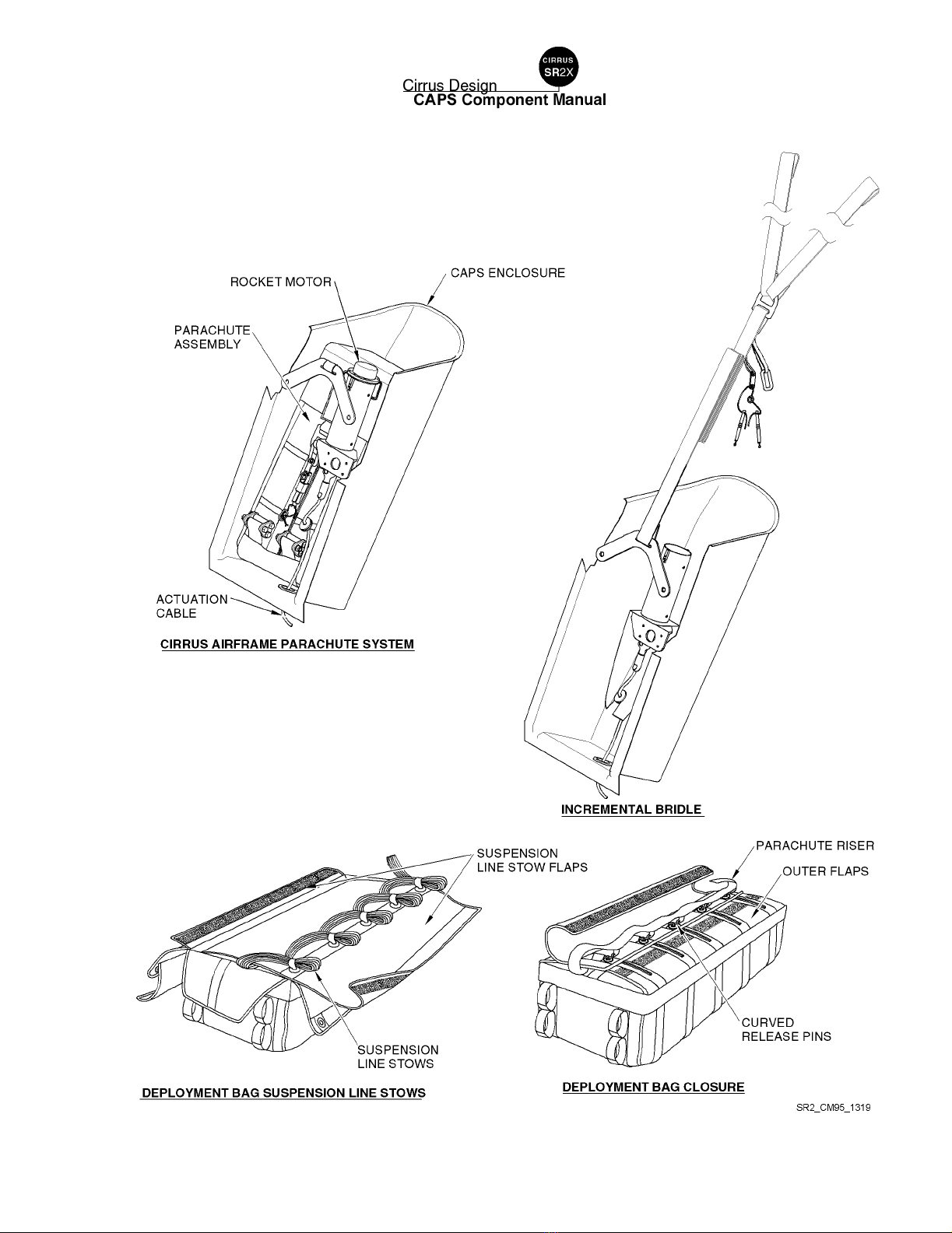
C. Incremental Bridle and Deployment Bag (See Figure 95-013)
The rocket motor is attached to the deployment bag via a set of Teflon sheathed stainless steel cables,
or rocket lanyards, and an incremental bridle. The incremental bridle consists a length of nylon web-
bing that is folded in half and sewn with a series of bartack stitches. Upon activation these stitches are
peeled away to provide proper rocket/bag dynamics by acting as a shock absorber. The incremental
bridle, which is connected to the end of the rocket lanyards is protected from the rocket exhaust by a
heavy kevlar sheath.
A deployment bag is used to contain the packed parachute assembly within the fuselage enclosure
and stage its deployment and inflation sequence. The parachute assembly is packed into two compart-
ments within the deployment bag. The innermost compartment contains the canopy and is secured by
an internal flap that is locked in place with a series of locking loops to ensure that the canopy cannot
be extracted from its compartment until the suspension lines, stored in the outer compartment, are
pulled taut, and the line stows are extracted from the locking loops that hold the flaps closed.
The suspension lines are secured with a hook and loop closure. The four outer flaps are secured with
five steel curved release pins attached to the riser. The pins are extracted when the riser is pulled taut
during extraction. The deployment bag creates an orderly deployment process by allowing the canopy
to inflate only after the rocket motor has pulled the aircraft attachment harness, riser and suspension
lines taut and pulled the deployment bag off the canopy. This prevents any slack or uneven tension in
the suspension lines during canopy inflation that could result in a malfunction.
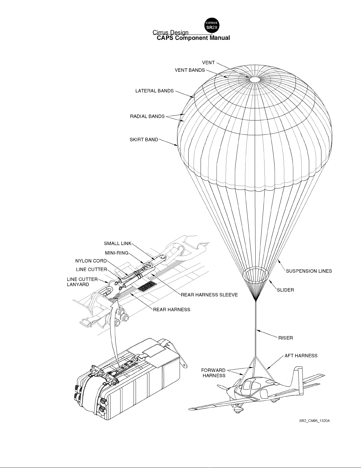
D. Parachute Assembly (See Figure 95-014)
The parachute slows the airplane to a descent speed that is conducive to a safe touchdown. The basic
structure of the parachute assembly consists of the canopy, suspension lines, and the slider; a compo-
nent used to aerodynamically reef the parachute and limit inflation loads.
(1) Canopy and Suspension Lines
The 2400 sq ft round canopy, which creates the aerodynamic drag, is made up of a series of fab-
ric panels sewn together to form its desired shape. The canopy has a vent at its center to allow
some air to escape in a controlled manner and thus reduce oscillations and provide a stable
descent. Vent lines are attached to the perimeter of the vent and routed symmetrically across its
center to provide structural support and maintain its shape.
The suspension lines are attached to the “skirt” of the canopy and converge to a riser or set of
risers at the opposite end. The canopy structural integrity is enhanced by a “skeleton” of tapes
and webbings sewn nearly perpendicular to each other to the top surface of the canopy fabric.
Radial bands run from opposite suspension line attachment points, across the top of the canopy.
The skirt band, vent band, and lateral bands run around the circumference of the canopy.
The CAPS parachute is fabricated from woven textiles in the form of fabrics, tapes, webbing, and
thread. All of the textile components in CAPS are fabricated from either Kevlar or Nylon and are
woven to military specifications that define specific parameters such as yarn count, yarn twist,
weave type, and finish. To insure good aging characteristics, the only exception to the use of
Kevlar and Nylon is a Teflon cloth buffer on the risers at the suspension line attachment point.
A typical deployment load profile begins with a snatch force which occurs when the parachute
assembly is initially extracted from its container and pulled to full line stretch. When air begins to
fill the canopy, inflation loads result. The parachute is designed to deploy without generating
forces high enough to injure the airplane occupants.
12128-001 95-01 Page 7
Figure 95-013
Incremental Bridle and Deployment Bag
15 Sept 2002

12128-001
95-01
Page 8 15 Sept 2002
(2) Slider
To limit inflation loads, CAPS uses a slider to aerodynamically reef the parachute. The slider is a
flat annular shaped fabric panel with metal grommets attached to its perimeter. The parachute
suspension lines are routed through the grommets so that the slider is free to move along the
suspension lines. The slider, which has a significantly smaller diameter than the fully inflated
parachute, is positioned at the top of the suspension lines, next to the canopy skirt, when the
parachute is packed. It therefore limits the initial inflated diameter of the parachute and hence
the inflation loads. During inflation, the slider remains next to the skirt for a period of time that is
dependent on the dynamic pressure acting on the system. This allows the payload to decelerate
to a speed at which the parachute can fully inflate without generating excessive loads.
E. Airplane Attachment Harness (See Figure 95-014)
An aircraft harness system connects the parachute risers to the airplane primary structure. The CAPS
aircraft harness consists of two forward harness straps attached to the firewall and a rear harness
attached to the FS 222 bulkhead located directly in front of the parachute enclosure. The CAPS har-
ness system is designed to control the pitch dynamics of the airplane during the deployment cycle by
limiting the aft aircraft attachment harness length until the deployment cycle is complete.
The rear harness assembly has two sections of different length. The shorter section has a mechanical
release mechanism that is activated by two pyrotechnic reefing line cutters. The fuses on these line
cutters are initiated when the line cutter release pin is pulled when the harness is pulled taut during the
extraction. After 8 seconds, the line cutters fire, the longer section of the rear harness takes over and
the airplane assumes its touchdown attitude, approximately ten degrees nose down, to optimize occu-
pant protection.
The release mechanism design is based on a 3-ring release mechanism. This system uses a series of
metal rings routed through each other in a manner that provides a significant mechanical advantage.
For the mechanism to be released, each link must rotate through its adjacent ring or link. The force
necessary to hold the small link in its stowed position is considerably smaller than the force that is
being applied as a result of the overall load on the mechanism. On the CAPS system the last link is
held in place by a short length of nylon cord which is severed by the pyrotechnic reefing line cutters.
12128-001 95-01 Page 9
Figure 95-014
Parachute Assembly and Line Cutters
15 Sept 2002

THIS PAGE INTENTIONALLY LEFT BLANK

12128-001 95-01 Page 1115 Sept 2002
MAINTENANCE GUIDE
1. GENERAL
Procedures and parts listed in this manual are reflective of Cirrus Design SR20 airplanes serial numbers
1195 and subsequent, SR22 airplanes serial numbers 0210 and subsequent, and all prior airplanes incor-
porating Service Bulletin SB 20-95-05 or SB 22-95-05 respectively.
WARNING: CAPS must be serviced and maintained by Cirrus Design trained and authorized para-
chute system technicians only. Airframe and Powerplant license is not sufficient cre-
dentials for performing maintenance on CAPS.
Never activate CAPS on the ground. The rocket exits the fuselage with a velocity of
150 mph in the first tenth of a second and reaches full extension in 2.5 seconds. Peo-
ple near the airplane may be injured and extensive damage to the airframe will occur.
Ground activation will cause the airplane to be out of service until CAPS is replaced
and the airframe repaired and inspected.
Rocket ignition will occur at temperature above 500° F (260° C). In the event of ground
fire, use necessary precautions to avoid CAPS deployment.
FAA Type Certification for the airplane is contingent on a functional Cirrus Airframe
Parachute System (CAPS). The airplane may not be flown when CAPS is rendered
inoperative.
Note: CAPS part identification and descriptions can be found in the Illustrated Parts List section of
this manual.
A. Servicing - Cirrus Airframe Parachute System (See Figure 95-015)
(1) Removal - Pyrotechnic Line Cutters Replacement
(a) Acquire necessary tools, equipment, and supplies.
(b) Remove CAPS handle access cover and install CAPS handle safety pin
(c) Remove bulkhead 222 (BH 222) trim panel and carpet.
(d) Remove access panel CB7 from BH 222. (Refer to AMM 6-00)
(e) To prevent debris and components from falling into bottom of empennage, place catch
cloth below rocket and parachute assembly.
(f) Pull open flaps secured with hook and loop to gain access to line cutters.
(g) Remove line cutter lanyard from D-ring and un-thread lanyard routed through line cutter’s
ignition loops.
WARNING: When cutting nylon cord, ensure three-ring assembly stackup is not
altered.
(h) Cut and remove nylon cord securing line cutters to link assembly.
(i) Remove line cutters from airplane and safely discard.
Description P/N or Spec. Supplier Purpose
Pyrotechnic Line Cutter
Replacement Kit
TBD Cirrus Design Replacment.

12128-001
95-01
Page 12 15 Sept 2002
(2) Installation - Pyrotechnic Line Cutters Replacement
(a) Ensure CAPS handle safety pin is installed.
(b) Verify three-ring release assembly is correct.
(c) Thread new nylon cord through mini-ring and pull cord ends equal.
(d) Thread nylon cord ends, through small link.
(e) Thread one end of nylon cord through installation hole on first new line cutter.
(f) Thread opposite end of nylon cord through installation hole on second new line cutter.
Note: Use a short, thin piece of wire wrapped around the nylon cord ends to facili-
tate routing the nylon cord through the rear harness sleeve.
(g) Wrap wire around nylon cord ends, insert wire into sleeve, and route cord through rear
harness sleeve.
(h) Pull nylon cord completely through sleeve so mini-ring cinches up against top surface of
small link.
(i) Position line cutters inside securing flaps and route nylon cord up, between link cutters.
(j) With one end of nylon cord make one complete loop around mini-ring.
CAUTION: Ensure no slack exists in nylon cord between rear harness sleeve and mini-
ring and line cutter installation holes and small link.
(k) Cinch nylon cord tight.
(l) Tie CAPS knot:
1Cross upper cord end (end looped around mini-ring) over lower cord end twice. i.e.
right over left, right over left.
2Cinch nylon cord tight.
3Tie standard Square Knot and cinch tight.
(m) Sew nylon cord ends together just below CAPS knot, tie off with CAPS knot.
CAUTION: Ensure trimmed ends of nylon cord do not interfere with line cutter’s ignition
loops.
(n) Trim nylon cord to one inch (2.5 cm).
(o) Route line cutter lanyard through line cutter’s ignition loops and secure lanyard to D-ring.
(p) Close hook and loop securing flaps.
(q) Remove catch cloth from below rocket and parachute assembly.
(r) Install access panel CB7 to BH 222.
(s) Install BH 222 trim panel and carpet.
Table of contents
Other CIRRUS DESIGN Aircraft manuals


