Cirrus SR22 User manual

CIRRUS AIRPLANE MAINTENANCE MANUAL MODELS SR22 AND SR22T
27-31
Page 1
All
EFFECTIVITY:
STALL WARNING SYSTEM
1. DESCRIPTION
A. Stall Warning System - Serials w/o Perspective Avionics
The airplane uses an electro-pneumatic stall warning system. As the angle of attack increases and the
airplane approaches an aerodynamic stall, the stagnation point moves lower on the leading edge
causing low pressure on the upper leading edge to increase. As low pressure passes over the stall
warning port located on the leading edge of the right wing, negative pressure is sensed by a pressure
switch which activates the stall warning horn.
The stall warning horn, located on the top flange of the LH center console rib, is a piezo-ceramic audio
indicator. Serials 22-0002 & subs before SB 2X-27-15: When activated, the horn supplies a continuous
94 dB, 2800 Hz tone. Serials 22-0002 & subs after SB 2X-27-15: When activated, the horn supplies a
continuous 95 dB, 2000 Hz tone.
The pressure switch, located on the mid-console LH side panel, is a normally open, diaphragm-oper-
ated switch. The switch is powered by 28 VDC supplied through the 2-amp STALL WARNING circuit
breaker on the Essential Bus.
B. Stall Warning System - Serials w/ Perspective Avionics and w/o FIKI
The airplane uses an electro-pneumatic stall warning system. As the angle of attack increases and the
airplane approaches an aerodynamic stall, the stagnation point moves lower on the leading edge
causing low pressure on the upper leading edge to increase.
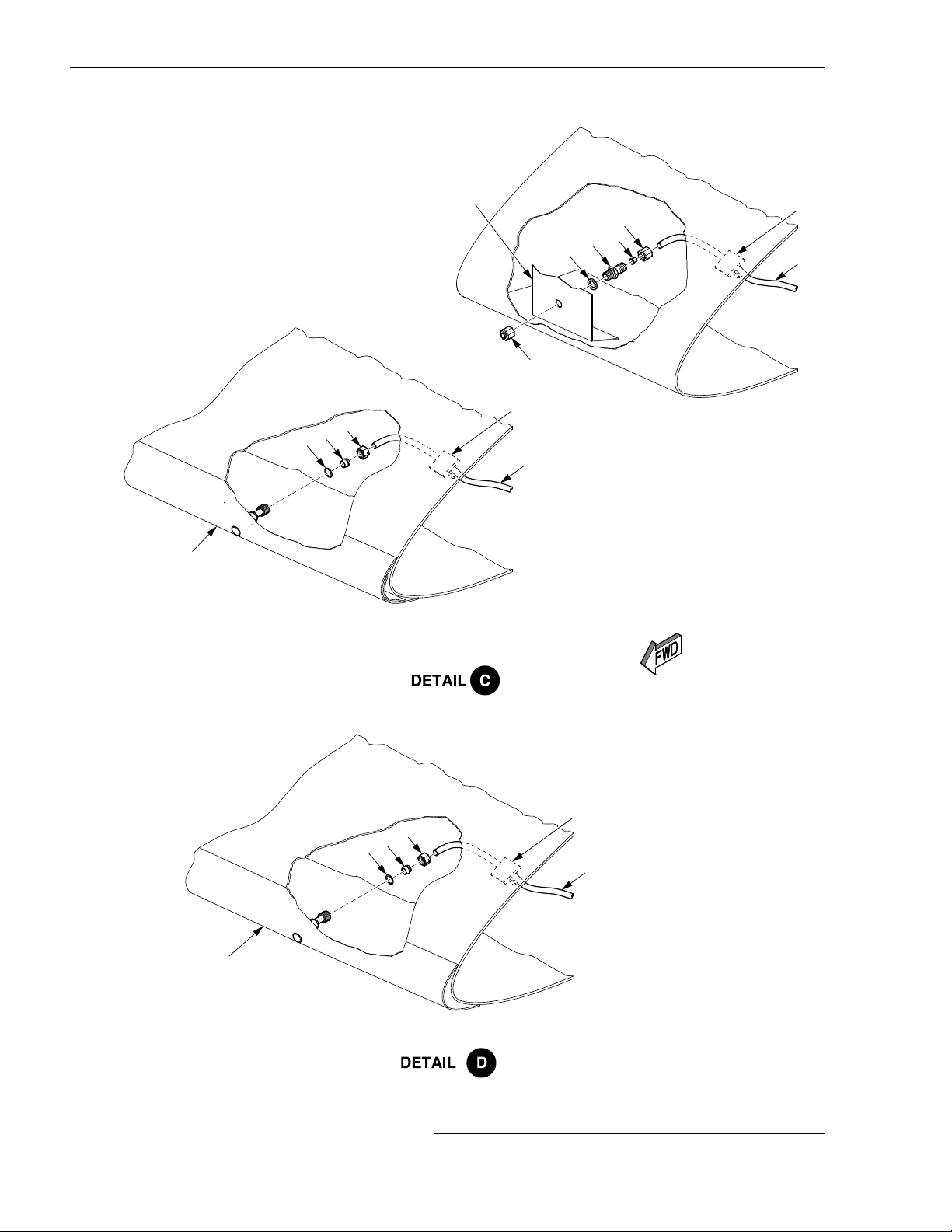
Serials 22-3026 thru 22-3402: As low pressure passes over the stall warning port located on the lead-
ing edge of the right wing, negative pressure is sensed by a pressure switch which activates the stall
warning horn. The stall warning horn, located on the upper surface of the GIA #2 rack, is a piezo-
ceramic audio indicator which, when activated, supplies a continuous 94 dB, 2800 Hz tone.
Serials 22-3403 & subs, 22T-0001 & subs: As low pressure passes over the stall warning port located
on the leading edge of the right wing, negative pressure is sensed by a pressure switch which provides
a signal to the avionics system to activate the aural stall warning and enables the Crew Alerting Sys-
tem (CAS) to display a STALL annunciation on the PFD.
The pressure switch, located on the mid-console LH side panel, is a normally open, diaphragm-oper-
ated switch. The switch is powered by 28 VDC supplied through the 2-amp STALL WARNING circuit
breaker on the Essential Bus.
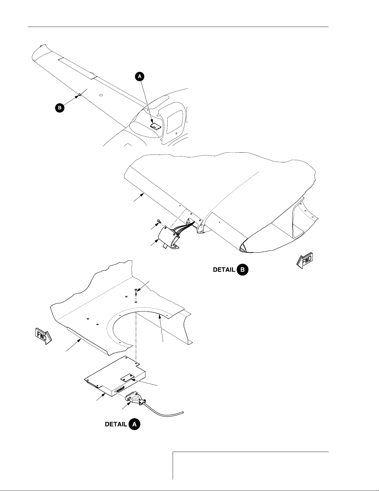
C. Stall Warning System - Serials w/ FIKI
The airplane uses an electro-mechanical lift transducer, mounted on the leading edge of the right wing.
As the angle of attack increases, the stagnation point moves below the transducer, increasing the
upward pressure on the spring loaded vane. The movement of the vane produces an electrical output
that is sent to a stall warning computer located under cabin access panel CF3R. The stall warning
computer provides a signal to the avionics system to activate the aural stall warning and enables the
Crew Alerting System (CAS) to display a STALL annunciation on the PFD. The transducer is powered
by exciter voltage supplied by the stall warning computer. The stall warning computer is powered by 28
VDC supplied through the 5-amp STALL WARNING circuit breaker on the Essential Bus.
15 Jun 2010

27-31
Page 2 Serials w/o Perspective Avionics
EFFECTIVITY:
CIRRUS AIRPLANE MAINTENANCE MANUAL MODELS SR22 AND SR22T
15 Jun 2010
2. MAINTENANCE PRACTICES
A. Stall Warning Horn - Serials w/o Perspective Avionics (See Figure 27-311)
(1) Removal - Stall Warning Horn
(a) Remove glareshield. (Refer to 25-10)
(b) Remove MFD. (Refer to 31-60)
(c) Disconnect stall warning horn electrical connector.
(d) Serials 22-0002 & subs before SB 2X-27-15: Remove screws, washers, and nuts securing
horn to console rib. Remove horn from airplane.
(e) Serials 22-0002 & subs after SB 2X-27-15: Remove bolt and nut securing horn assembly
mounting bracket to console rib. Remove horn assembly from airplane.
(2) Installation - Stall Warning Horn
(a) Serials 22-0002 & subs before SB 2X-27-15: Position horn to console rib and secure with
screws, washers, and nuts.
(b) Serials 22-0002 & subs after SB 2X-27-15: Position horn assembly mounting bracket to
console rib at a 45o±5oangle and secure with bolt and nut.
(c) Connect stall warning horn electrical connector.
(d) Install MFD. (Refer to 31-60)
(e) Install glareshield. (Refer to 25-10)
(f) Perform Operational Check - Stall Warning System - Ground. (Refer to 27-31)
(g) Perform Operational Check - Stall Warning System - Flight. (Refer to 27-31)

CIRRUS AIRPLANE MAINTENANCE MANUAL MODELS SR22 AND SR22T
27-31
Page 3
Serials 22-3026 thru 22-3402 w/ Perspective Avionics
EFFECTIVITY:
B. Stall Warning Horn - Serials 22-3026 thru 22-3402 w/ Perspective Avionics (See Figure 27-311)
(1) Removal - Stall Warning Horn
(a) Remove MFD. (Refer to 31-60)
(b) Disconnect stall warning horn electrical connector.
(c) Remove screws and nuts securing horn to GIA #2 rack. Remove horn from airplane.
(2) Installation - Stall Warning Horn
(a) Position horn to GIA #2 rack and secure with screws and nuts.
(b) Connect stall warning horn electrical connector.
(c) Install MFD. (Refer to 31-60)
(d) Perform Operational Check - Stall Warning System - Ground. (Refer to 27-31)
(e) Perform Operational Check - Stall Warning System - Flight. (Refer to 27-31)
31 May 2011

27-31
Page 4 Serials w/o FIKI
EFFECTIVITY:
CIRRUS AIRPLANE MAINTENANCE MANUAL MODELS SR22 AND SR22T
15 Jun 2010
C. Stall Warning Pressure Switch - Serials w/o FIKI (See Figure 27-311)
(1) Removal - Stall Warning Pressure Switch
(a) Set BAT 1, BAT 2, and AVIONICS switches to OFF positions.
(b) Pull STALL WARNING circuit breaker.
(c) Remove LH mid-console circuit breaker trim panel. (Refer to 25-10)
(d) Open circuit breaker panel.
(e) Disconnect pressure switch electrical connector.
(f) Disconnect stall warning line from pressure switch.
(g) Remove screws, washers, and nuts securing pressure switch to console. Remove pres-
sure switch from airplane.
(2) Installation - Stall Warning Pressure Switch
(a) Position pressure switch to console and secure with screws, washers, and nuts.
(b) Connect stall warning line to pressure switch.
(c) Connect pressure switch electrical connector.
(d) Close circuit breaker panel.
(e) Install LH mid-console circuit breaker trim panel. (Refer to 25-10)
(f) Reset STALL WARNING circuit breaker.
(g) Perform Operational Check - Stall Warning System - Ground. (Refer to 27-31)
(h) Perform Operational Check - Stall Warning System - Flight. (Refer to 27-31)
(3) Operational Check - Stall Warning System - Ground
(a) Acquire necessary tools, equipment, and supplies.
(b) On RH wing leading edge, clean area surrounding stall warning port.
(c) Moisten suction cup and firmly press cup over stall warning port.
(d) Activate stall warning pressure switch by sharply pulling suction cup directly away from
stall warning port. Verify horn sounds audible warning signal.
(4) Operational Check - Stall Warning System - Flight
WARNING: The following Operational Check must be performed by a Cirrus Design
authorized test pilot.
(a) Remove access cap covering stall warning pressure switch located on lower portion of the
left mid-console circuit breaker trim panel.
(b) Perform Operational Check - Stall Warning System - Ground. (Refer to 27-31)
(c) In smooth air and at an altitude appropriate for stalls, place airplane in stall attitude.
(d) Record airplane speed that stall warning signal sounds.
(e) Record airplane speed that stall occurred.
(f) Stall warning signal should sound 5 to 10 KIAS prior to stall.
(g) If necessary, adjust stall warning pressure switch until stall warning signal sounds 5 to 10
KIAS prior to stall.
1Rotating the adjustment screw 1 full turn clockwise will raise the speed at which the
stall warning horn sounds by approximately 2 knots.
2Rotating the adjustment screw 1 full turn counterclockwise will lower the speed at
which the stall warning horn sounds by approximately 2 knots.
Description P/N or Spec. Supplier Purpose
Suction Cup - Any Source Application of negative pressure.

CIRRUS AIRPLANE MAINTENANCE MANUAL MODELS SR22 AND SR22T
27-31
Page 5
Serials w/o FIKI
EFFECTIVITY:
Figure 27-311
Stall Warning System- Serials w/o FIKI (Sheet 1 of 2)
FUSELAGE
(REF)
Serials 22-3026 thru 22-3402
w/ Perspective Avionics.
GIA #2
RACK
(REF)
SR22_MM27_1380E
CENTER
CONSOLE
(REF)
FUSELAGE
(REF)
CABIN FLOOR (REF)
LEGEND
1. Stall Warning Horn
2. Screw
3. Washer
4. Nut
5. Electrical Connector
6. Electro-Pneumatic Switch
7. Spring Clamp
8. Pneumatic Line
9. Tee Fitting
10. Tie Down
11. Fitting
12. Plug
13. Grommet
14. Bolt
10
4
12
11
8
12
4
10
8
7
8
13
9
4
32
6
7
9
13
8
8
10
4
3
2
1
5
1
1
4
14
NOTE
Position bracket to rib at a 45º ±5º angle to the
rib, and secure using bolt and nut.
Serials 22-0002 & subs
w/o Perspective Avionics
before SB 2X-27-15.
4
2
Serials 22-0002 & subs
w/o Perspective Avionics
after SB 2X-27-15.
45º ±5º
LH INBOARD
CONSOLE RIB
(REF)
Serials 22-0334 & subs, 22T-0001 & subs
w/ Basic / Basic² Ice Protection, and/or
Serials 22-3026 & subs
w/ Perspective Avionics.
Serials 22-0002 & subs
w/o Ice Protection, and
Serials 22-3026 & subs
w/o Perspective Avionics.
31 May 2011

27-31
Page 6 Serials w/o FIKI
EFFECTIVITY:
CIRRUS AIRPLANE MAINTENANCE MANUAL MODELS SR22 AND SR22T
15 Jun 2010
Figure 27-311
Stall Warning System - Serials w/o FIKI (Sheet 2 of 2)
SR22_MM27_1674B
Serials 22-0002 thru 22-2437
w/o Ice Protection.
Serials 22-0334 thru 22-2437
w/ Ice Protection.
STALL WARNING
ENCLOSURE (REF)
Serials 22-2438 thru 22-3402, 22-3403 & subs,
22T-0001 & subs w/o FIKI.
POROUS PANEL
(RED)
LEGEND
4. Nut
8. Pneumatic Line
10. Tie Down
15. Bulkhead Union
16. Nylon Insert
17. O-Ring
18 . Olive
17
LEADING EDGE PANEL
(REF)
4
18
17
16
15
17
4
18
8
10
8
10
4
4
8
10

CIRRUS AIRPLANE MAINTENANCE MANUAL MODELS SR22 AND SR22T
27-31
Page 7
Serials w/ FIKI
EFFECTIVITY:
D. Stall Warning Lift Transducer - Serials w/ FIKI (See Figure 27-312)
(1) Removal - Stall Warning Lift Transducer
(a) Set BAT 1, BAT 2, and AVIONICS switches to OFF positions.
(b) Pull STALL WARNING circuit breaker.
(c) Pull STALL VANE HEAT circuit breaker.
(d) Remove screws securing lift transducer to wing.
(e) Disconnect wing wire harness connectors from lift transducer pigtail connectors.
(f) Remove lift transducer from wing.
(2) Installation - Stall Warning Lift Transducer
(a) Acquire necessary tools, equipment, and supplies.
(b) Connect wing wire harness connectors to lift transducer pigtail connectors.
(c) Position lift transducer to wing and secure with screws.
(d) Apply sealant to perimeter of lift transducer.
(e) Reset STALL VANE HEAT circuit breaker.
(f) Test lift transducer heat.
1On bolster panel, set PITOT HEAT switch to ON.
CAUTION: The surfaces of the heated stall vane and plate are very hot. Do not
touch or injury will occur.
2Carefully feel for heat near lift transducer stall vane and plate.
3Set PITOT HEAT switch to OFF.
(g) Reset STALL WARNING circuit breaker.
(h) Perform Operational Check - Stall Warning System - Ground. (Refer to 27-31)
(i) Perform Operational Check - Stall Warning System - Flight. (Refer to 27-31)
(3) Functional Test - Stall Warning Lift Transducer
(a) Acquire necessary tools, equipment, and supplies.
(b) Remove wing access panel RW9. (Refer to 06-00)
(c) Disconnect P442 connector from lift transducer.
(d) Using ohmmeter, measure resistance of lift transducer components.
1Measure pins A and E to verify case heater resistance equals 39.0 ± 5.8 ohms.
2Measure pins B and C to verify mounting plate #1 resistance equals 9.2 ± 1.4 ohms.
3Measure pins D and G to verify mounting plate #2 resistance equals 9.2 ± 1.4 ohms.
4Measure pins F and G to verify vane heater resistance equals 37.2 ± 5.6 ohms.
(e) Connect P442 connector to lift transducer.
(f) Install wing access panel RW9. (Refer to 06-00)
Description P/N or Spec. Supplier Purpose
Sealant (Refer to 51-
30)
(Refer to 51-30) Seal perimeter of lift
transducer.
Description P/N or Spec. Supplier Purpose
Ohmmeter - Any Source Measure resistance.
15 Jun 2010

27-31
Page 8 Serials w/ FIKI
EFFECTIVITY:
CIRRUS AIRPLANE MAINTENANCE MANUAL MODELS SR22 AND SR22T
15 Jun 2010
E. Stall Warning Computer - Serials w/ FIKI (See Figure 27-312)
(1) Removal - Stall Warning Computer
(a) Set BAT 1, BAT 2, and AVIONICS switches to OFF positions.
(b) Pull STALL WARNING circuit breaker.
(c) Remove access panel CF3R. (Refer to 06-00)
(d) Disconnect electrical connector from stall warning computer.
(e) Remove screws securing stall warning computer to fuselage floor. Remove stall warning
computer from airplane.
(2) Installation - Stall Warning Computer
(a) If installing a new or different stall warning computer, perform Adjustment/Test - Stall
Warning Computer Switch Settings. (Refer to 27-31)
(b) Position stall warning computer to fuselage floor and secure with screws.
(c) Connect electrical connector to stall warning computer.
(d) Reset STALL WARNING circuit breaker.
(e) Perform Operational Check - Stall Warning System - Ground. (Refer to 27-31)
(f) Install access panel CF3R. (Refer to 06-00)
(3) Adjustment/Test - Stall Warning Computer Switch Settings
(a) Loosen screws securing switch access covers to existing and new computers.
(b) Verify switch positions of existing computer match values entered in aircraft logbook.
(c) Adjust SW and VR rotary switch settings on new computer to match existing computer
switch settings.
(d) Record switch settings in aircraft logbook.
(e) On stall warning computers, rotate switch access covers to closed positions and tighten
screws.
(4) Operational Check - Stall Warning System - Ground
(a) Acquire necessary tools, equipment, and supplies.
(b) Remove access panel CF3R. (Refer to 06-00)
(c) Loosen screws securing switch access cover to stall warning computer.
Note: Switch access cover is marked with relative location of “SW” and “VR”
rotary switches and 4 LED indicators marked VAL (Valid), LTF (Lift Trans-
ducer Fault), AIR (Air Mode), and ICE (Ice Protection On).
(d) Set BAT1 switch to ON position.
(e) On stall warning computer, verify red “LTF” LED is not on.
(f) Set FLAPS switch to 100% position.
(g) On stall warning computer, verify that “VAL” and “AIR” LEDs are on (green).
CAUTION: The surfaces of the heated stall vane and plate are very hot. Do not touch or
injury will occur.
(h) On right wing, use wooden tongue depressor to gently apply upward pressure on tab of lift
transducer and note stall warning horn sounds.
(i) Set FLAPS switch to UP position.
Description P/N or Spec. Supplier Purpose
Wooden Tongue
Depressor
- Any Source Fixture.

CIRRUS AIRPLANE MAINTENANCE MANUAL MODELS SR22 AND SR22T
27-31
Page 9
Serials w/ FIKI
EFFECTIVITY:
(j) Set BAT1 switch to OFF position.
(k) On stall warning computer, rotate switch access cover to closed position and tighten
screws.
(l) Install access panel CF3R. (Refer to 06-00)
(5) Operational Check - Stall Warning System - Flight
WARNING: The following Operational Check must be performed by a Cirrus Design
authorized test pilot.
(a) Remove access panel CF3R. (Refer to 06-00)
(b) Loosen screws securing switch access cover to stall warning computer.
Note: Switch access cover is marked with relative location of “SW” and “VR”
rotary switches and 4 LED indicators marked VAL (Valid), LTF (Lift Trans-
ducer Fault), AIR (Air Mode), and ICE (Ice Protection On).
(c) In smooth air and at an altitude appropriate for stalls, place airplane in stall attitude.
(d) Record airplane speed that stall warning signal sounds.
(e) Record airplane speed that stall occurred.
Note: Stall warning signal should sound 5 to 10 KIAS prior to stall.
(f) If stall warning signal does not sound 5 to 10 KIAS prior to stall, adjust the “SW” 8-position
rotary switch.
1Rotate clockwise, one detent at a time, to decrease speed at which stall warning
horn sounds.
2Rotate counter-clockwise, one detent at a time, to increase speed at which stall
warning horn sounds.
(g) On stall warning computer, rotate switch access cover to closed position and tighten
screws.
(h) Install access panel CF3R. (Refer to 06-00)
15 Jun 2010

27-31
Page 10 Serials w/ FIKI
EFFECTIVITY:
CIRRUS AIRPLANE MAINTENANCE MANUAL MODELS SR22 AND SR22T
15 Jun 2010
Figure 27-312
Stall Warning System- Serials w/ FIKI
SWITCH ACCESS
COVER (REF)
SR22_MM27_2994
LEGEND
1. Stall Transducer
2. Screw
3. Connector
4. Stall Computer
RH OUTBOARD
POROUS PANEL
(REF)
CF3R (REF)
2
2
1
3
4
AFT FLOOR
(REF)
Other manuals for SR22
27
This manual suits for next models
1
Table of contents
Other Cirrus Aircraft manuals

Cirrus
Cirrus SR20 Quick setup guide

Cirrus
Cirrus SR22 User manual

Cirrus
Cirrus SR20 User manual

Cirrus
Cirrus SR22 User manual

Cirrus
Cirrus SR20 Owner's manual

Cirrus
Cirrus SR22 User manual

Cirrus
Cirrus SR22T Owner's manual

Cirrus
Cirrus SR20 User manual

Cirrus
Cirrus SR22 Owner's manual

Cirrus
Cirrus SR22 User manual