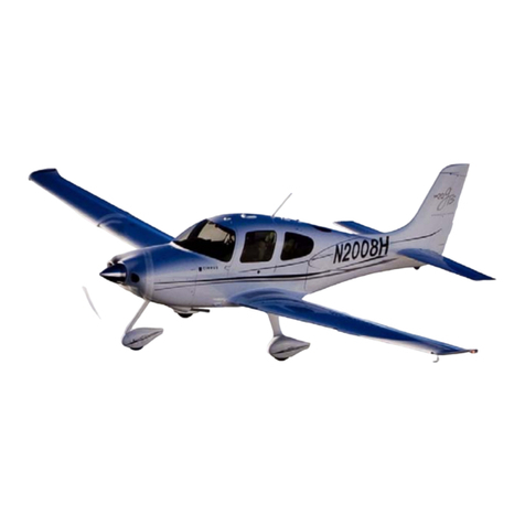
Cirrus SR20 User manual

CIRRUS AIRCRAFT WIRING MANUAL MODEL SR20
20-00
Page 1
All
EFFECTIVITY:
STANDARD PRACTICES: WIRING
1. GENERAL
This chapter contains requirements and procedures for the fabrication, repair, and marking of wire harness
assemblies, cables, and wires. All wiring repairs and marking of wire harness assemblies, cables, and
wires should be accomplished in accordance with the procedures in this chapter and in accordance with
FAA Advisory Circular AC 43-13 (latest revision).
A. Terminology
The following terms are used throughout this chapter. The maintenance technician should be familiar
with the following definitions, materials, and procedures:
• Wire: An individual insulated wire. Either stranded or solid.
• Cable: A multi-conductor cable. In most cases this is a shielded twisted-wire cable that is jacketed
with a Teflon material.
• Wire: Bundle A group of wires and/or cables that are tied together using tie string, tie wraps, or
other methods. In some cases the wire bundle may be covered with an external sheath.
• Wire Harness: A complete assembly including a wire bundle and the associated connectors, fas-
teners, and markings.
• Plug: A connector with female pins (sockets) normally used on the power side (coming from an
electrical source) of a connection of two or more bundles or devices.
• Jack: A connector with male pins normally used on the device side of a connection.
B. Wire and Cable Marking
Wire marking aids the technician in locating and identifying individual wires within a wire bundle. Wire
marking consists of a combination of letters and numbers that identify the wire, circuit or system, wire
gauge, and additional data that helps in wire identification.
(1) Numbering
(a) Wires are numbered to identify the system, circuit, wire number, wire gauge, and signal
type. For example, wire ANGP003-20N indicates a 20 AWG ground wire for the GPS
receiver.
(b) Each wire is numbered within 6 inches of the termination at each end and every 12 to 15
inches along the length of the wire with the following exceptions:
1Wires less than 6 inches in length may not be marked.
2Wires installed within conduit are marked within 6 inches of termination ends.
3Wires 6 to 24 inches in length and having one end terminated by a terminal ring,
spade lug, or soldered to a device are marked by a single marker on the external
connector end.
4Assemblies consisting of a single wire with terminal rings or spade lugs on each end
and not having a wire number are not marked but are labeled with the part's assem-
bly number and revision level.
5Wires 6 to 24 inches in length, not meeting the above criteria, are marked within 6
inches of each termination end.
(2) Marking
(a) Wires are marked by stamping directly onto the wire insulation, or are marked by attaching
printed sleeving or tape.
(b) Each wire and/or cable is marked by using the codes listed in Figure 20-001.
19 Sep 2010

20-00
Page 2 All
EFFECTIVITY:
CIRRUS AIRCRAFT WIRING MANUAL MODEL SR20
19 Sep 2010
C. Wire Harness Marking
Wire harnesses are also marked for ease of identification during fabrication and installation. Wire har-
nesses are marked using the following methods:
(1) Markings
Each wire harness shall be marked with a unique number that identifies its location in the air-
plane. Wire harness numbers shall start with a “W” followed by a unique three (3) digit number
that corresponds to the wire harness location. The following numbering convention is used:
(a) 001-299 Firewall Forward
(b) 300-399 Left Wing
(c) 400-499 Right Wing
(d) 500-999 Fuselage
Wire harnesses are marked with a tag that identifies the wire harness number and the wire har-
ness part number. This tag is attached to the wire harness adjacent to the plug or jack that pro-
vides primary power or signals to the wire harness.
D. Plug and Jack Marking
Plugs and jacks are marked to aid in identification during fabrication, installation, and troubleshooting.
Plugs and jacks are be marked using the following methods:
(1) Markings
Plugs and jacks are marked with a unique number that identifies their location in the airplane.
The first character is a “P” for plugs or a “J” for jacks. The plug or jack designation is followed by
a unique three (3) digit number that corresponds to the plug/jack location. The following number-
ing convention is used:
(a) 001-299 Firewall Forward
(b) 300-399 Left Wing
(c) 400-499 Right Wing
(d) 500-999 Fuselage
Plugs and jacks are marked with a tag that identifies the plug or jack number. This tag is
attached to the wire harness adjacent to the plug or jack.
Relay bases or sockets do not require marking. Bases are directly marked with paint or visible
permanent marker with the base identification number.

CIRRUS AIRCRAFT WIRING MANUAL MODEL SR20
20-00
Page 3
All
EFFECTIVITY:
SYSTEM / CODE CIRCUIT, GENERAL CIRCUIT, SPECIFIC
Power (P)
BAPR Generation Battery 2
PAC Power Air Conditioning
PACC Power Autopilot
PACF Ground PFD Cooling Fan
PADL Power ADL
PAPS Power Pitch Servo
PARS Power Roll Servo
PAYS Power Yaw Servo
PBLU Ground Air Conditioning
PCAU Power Audio Panel
PCP Power Convenience Power
PCPR Power Convenience Power
PDM Power DME
PEP Entertainment Power
PFD Navigation Display
PG Shield Ground Flaps
PGAL Generation Alternator
PGCB Generation Circuit Breaker
PGCF Power Avionics Cooling Fan
PGEA Power GEA
PGLV Generation Low Voltage
Figure 20-001
Wire Number Codes (Sheet 1 of 4)
XXXX0000 - XX (X)
SYSTEM FUNCTION
CIRCUIT GENERAL
CIRCUIT SPECIFIC
SIGNAL TYPE
N = Ground
WIRE GAUGE
WIRE NUMBER
000 - 299, 5000 - 5999 Firewall Forward
300 - 399, 3000 - 3999 Left Wing
400 - 499, 4000 - 4999 Right Wing
500 - 999, 1000 - 2999 Fuselage
31 May 2011

20-00
Page 4 All
EFFECTIVITY:
CIRRUS AIRCRAFT WIRING MANUAL MODEL SR20
19 Sep 2010
PGMS Generation Master Switch
PGST Generation Starter
PMCF Power MFD Cooling Fan
PNAD Power ADF
PNDM Power DME
PPCF Power PFD Cooling Fan
PRDM Power ADL
PXF Power Transponder Cooling Fan
PXM Power XM Weather
Avionics (A)
AACC Autopilot Controller/Computer
AAGP Autopilot GPS
AAPT Autopilot Pitch Trim
AART Autopilot Roll Trim
ACAU Communications Audio
ACEA Data GEA
ACEL Shield Ground ELT
ACFD Switch TO/GA Switch
ACMD MFD Display
ACMS Switch Avionics Switch
ACPD Data PFD
ACSB Data GEA
ACTL Communications Telephone
ACTX Communications Transponder
ACVH Communications VHF Radio
AEVS Data EVS
ANAD Navigation ADF
ANAU Navigation Audio
ANDM Navigation DME
ANEG Navigation TAWS
SYSTEM / CODE CIRCUIT, GENERAL CIRCUIT, SPECIFIC
Figure 20-001
Wire Number Codes (Sheet 2 of 4)

CIRRUS AIRCRAFT WIRING MANUAL MODEL SR20
20-00
Page 5
All
EFFECTIVITY:
ANFM Power Keypad
ANGP Navigation GPS
ANHS Navigation HSI
ANMD Navigation Display
ANRS Data AHRS, Air Data
ANSK Data Skywatch
ANSS Data Stormscope
ANTA Power Skywatch
ANVH Navigation VHF Radio
ANXM Data XM Weather
Instruments (I)
ANEN Power Engine Instruments
IEFL Engine Indicator Fuel Level
IEHB Engine Indicator Hobbs
IEOP Engine Indicator Oil Pressure
IEOT Engine Indicator Oil Temperature
INFD Navigation Flux Detector
INHS Navigation HSI
IPAT Power Attitude 2
IPCL Power Clock
IPEI Power Engine Instruments
IPHS Power HSI
IPTC Power Turn Coordinator
IPVA Power Volt/Amp
IPYT Power Yaw Trim
ISAN System Indicator Annunciator
ISOA System Indicator OAT
Engine (E)
EEFP Electric Fuel Pump
EFGS Switch Gascolator
SYSTEM / CODE CIRCUIT, GENERAL CIRCUIT, SPECIFIC
Figure 20-001
Wire Number Codes (Sheet 3 of 4)
19 Sep 2010

20-00
Page 6 All
EFFECTIVITY:
CIRRUS AIRCRAFT WIRING MANUAL MODEL SR20
19 Sep 2010
EPMA Power Magnetos
Lights (L)
LELD Exterior Landing
LENV Exterior Navigation
LEST Exterior Strobe
LIBG Interior Baggage
LICB Power Attitude 2
LIFL Interior Flood
LIIL Interior Instrument Lights
LILS Ground Dimmer Switch
Controls (C)
CAC Control Air Conditioning
CASD Switch Autopilot Disconnect
CFL Flaps
CPT Pitch Trim
CRT Roll Trim
CSAC Power Air Conditioning
CSAV Switch Avionics Switch
CSIC Power Ice Protection
CSMS Switch Master Switch
CSST Switch Starter Switch
CSTM Switch Trim Switch
CSVA Switch Vacuum
CSYT Switch Yaw Trim
SSW Switch Stall Warning
SYSTEM / CODE CIRCUIT, GENERAL CIRCUIT, SPECIFIC
Figure 20-001
Wire Number Codes (Sheet 4 of 4)

CIRRUS AIRCRAFT WIRING MANUAL MODEL SR20
20-00
Page 7
All
EFFECTIVITY:
2. FAULT ISOLATION
Malfunction symptoms will normally be a result of operational checkout or functional test procedures that
fail at some point. Discrepancies must be resolved before the procedures can be completed. Another
source of malfunction symptoms are the crew member squawks.
WARNING: Use extreme caution when performing maintenance operations on the airplane.
Unless otherwise instructed, troubleshooting will be performed with the system de-
energized.
If a circuit is being tested with a lampload or a Meggar which may result in arcing,
safety procedures relating to fuel vapors must be observed.
Do not wear rings, wrist watches, metal bracelets, or other jewelry which can cause a
short circuit resulting in serious injury.
Repairing or troubleshooting of wiring must be accomplished by referring to the electrical wiring diagrams
contained in this manual.
After the malfunction is cleared, perform appropriate operational checkout or functional test procedure.
In light circuits with only one lamp, the isolation procedure usually starts with the possibility of a defective
lamp. In a light circuit that has two or more lamps, the isolation procedures do not isolate defective lamps.
A fault that results from shorted light circuits is often caused by foreign metal objects that have fallen into
the wiring or by pinched wires resulting from maintenance work on other equipment in the area. A thorough
visual inspection may often locate a fault in shorted light circuits.
A. Test Leads
When using test leads to make voltage checks, the following procedures shall be followed:
(1) Inspection/Test
(a) Remove system power.
(b) Disconnect applicable connector.
(c) Install test lead between designated connector or receptacle pins which complete circuit to
be tested.
(d) Apply system power and perform check.
19 Sep 2010

20-00
Page 8 All
EFFECTIVITY:
CIRRUS AIRCRAFT WIRING MANUAL MODEL SR20
19 Sep 2010
Intentionally Left Blank
Other manuals for SR20
15
Table of contents
Other Cirrus Aircraft manuals

Cirrus
Cirrus SR20 User manual

Cirrus
Cirrus SR22 User manual

Cirrus
Cirrus SR20 User manual

Cirrus
Cirrus SR20 User manual

Cirrus
Cirrus SR22 User manual

Cirrus
Cirrus SR22 User manual

Cirrus
Cirrus SR22 User manual

Cirrus
Cirrus SR20 User manual

Cirrus
Cirrus SR22 User manual

Cirrus
Cirrus SR22 Technical specifications

Cirrus
Cirrus SR22 User manual

Cirrus
Cirrus SR22 User manual

Cirrus
Cirrus SR22 User manual

Cirrus
Cirrus SR20 User manual

Cirrus
Cirrus SR22 User manual

Cirrus
Cirrus SR22 Owner's manual

Cirrus
Cirrus SR22 Owner's manual

Cirrus
Cirrus SR22 Owner's manual

Cirrus
Cirrus SR20 Owner's manual

Cirrus
Cirrus SR22 User manual