Cirs QA Phantom 008Z User manual
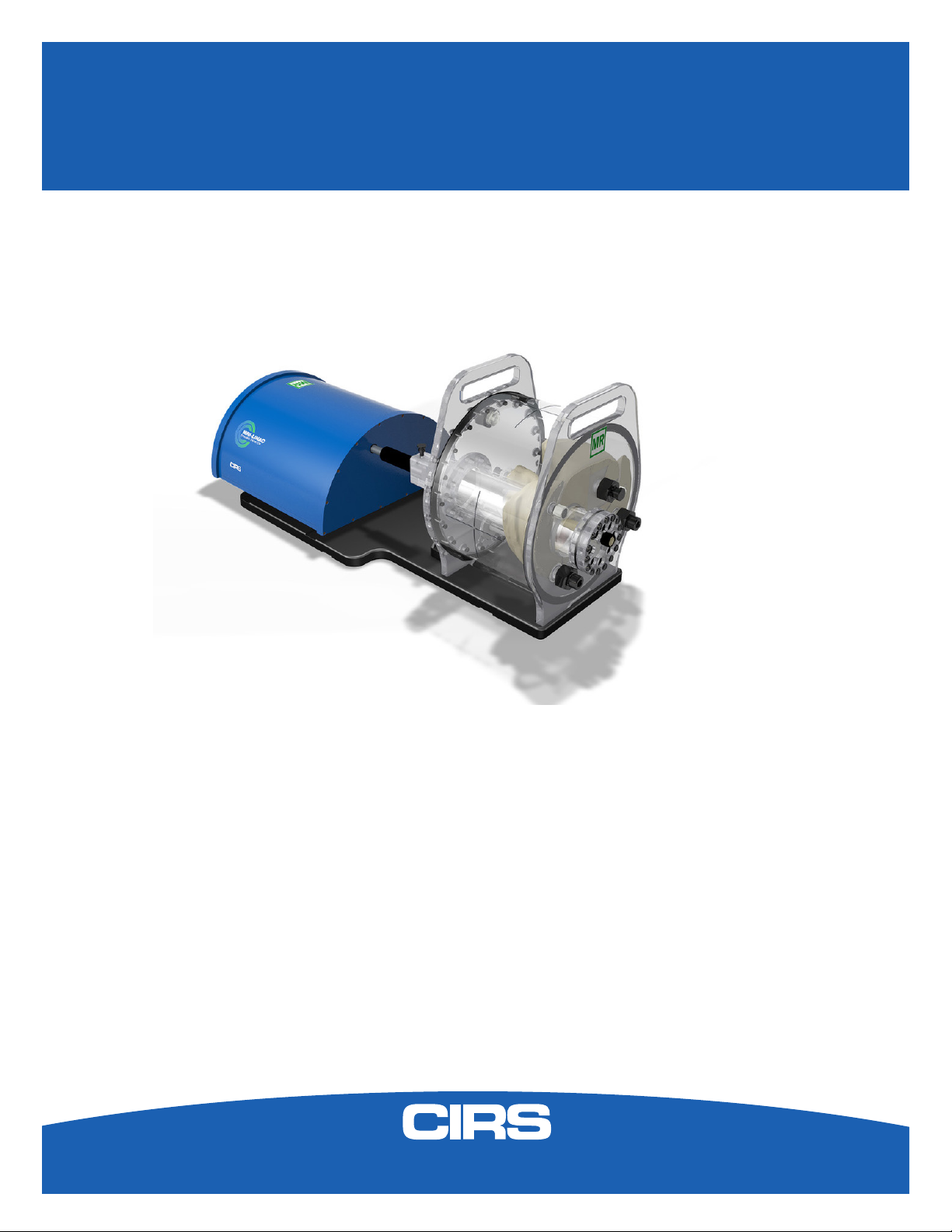
IMAGE ACQUISITION • TREATMENT PLANNING • DOSE DELIVERY
USER GUIDE
MRgRT Motion Management
QA Phantom
Model 008Z
900 Asbury Ave • Norfolk, Virginia 23513 • USA • Tel: 757-855-2765 • WWW.CIRSINC.COM

Overview . . . . . . . . . . . . . . . . . . . . . . . . . . . .3
Safety . . . . . . . . . . . . . . . . . . . . . . . . . . . . . 4
Unpacking Instructions . . . . . . . . . . . . . . . . . . . . . . 5
Model 008Z Assembly Procedure . . . . . . . . . . . . . . . . . .6
Model 008Z Cables and Connections . . . . . . . . . . . . . . . . 7
Setup notes for Dynamic Phantoms with controller connecting to a PC using
an Ethernet connection . . . . . . . . . . . . . . . . . . . . . .8
CIRS Motion Control Software . . . . . . . . . . . . . . . . . . 10
Model 008Z Specications . . . . . . . . . . . . . . . . . . . 11
Warranty . . . . . . . . . . . . . . . . . . . . . . . . . . . 12
Notes . . . . . . . . . . . . . . . . . . . . . . . . . . . . 13
Table of Contents

3
The integration of MR imaging in radiation therapy facilitates real time motion
management.
The CIRS MRgRT Motion Management QA phantom is designed to address
such needs. The phantom is MR Safe due to the use of piezoelectric motors
and non-ferro-magnetic materials. The two piezoelectric motors move a cylin-
drical insert, which contain a tracking target, through a gel/liquid llable body
by rotating it independently from the motion in the Inferior-Superior direction.
The moving insert contains an organic shaped target (tumor) lled with gel,
which is surrounded by the same background gel used to ll the body. The
body represents a heterogenous background due to simulated lungs, liver,
kidney and spine. The simulated organs are anatomical in shape and have a
life-like spatial relationship. They are lled with gels that provide contrast in CT
and MR versus the background gel, which lls the void between the organs.
Besides imaging, all organs, except for the lungs, offer ion chamber dosimetry
cavities, which allow for completing an entire QA process; from imaging to
planning to verication of dose delivered.
Our phantom is designed as a single unit with a piezo actuator xed perma-
nently to a base plate on which the MRI body “snaps”. This allows for quick
setup, removal, lling, and storage purposes. The phantom’s base plate has
machined slots on the bottom, which allow for the use of indexing bars for
precise and repeatable/reproducible phantom-MRI (MRI-Linac) alignment.
Overview
Key Features
•
Non-ferromagnetic materials
=> MR safe
•
Allows for positioning within
magnet bore due to piezo
electric motors
•
Organic shaped Organs at
Risk and moving target
•
Can be imaged in MRI, CT,
and hybrid systems
•
Ion chamber dosimetry in
Liver, Kidney, Spine and
moving target
•
Calculate Beam latency for
each breathing cycle and as
an average of all executed
cycles without the need of an
external oscilloscope.
•
3D tissue equivalent Spine for
bone landmark

4
GENERAL SAFETY NOTICE
Warnings and Cautions are identied throughout this user guide to alert users of dangerous conditions that are created when instructions are
not followed. Operation and maintenance personnel must observe all safety regulations. For the purposes of this manual, cautions are identied
as situations that can cause damage to the phantom and internal electronics. Warnings are dened as conditions that can cause injury to the
operator.
WARNING:
HIGH VOLTAGES CAPABLE OF CAUSING DEATH ARE USED IN THIS EQUIPMENT. USE EXTREME CAUTION
WHEN OPERATING AND SERVICING THE CONTROLLER. DEENERGIZING THE CONTROLLER BY USING THE
POWER SWITCH DOES NOT REMOVE THE 110-250 VAC POWER EXCITATION FROM THE CONTROLLER.
THESE VOLTAGES REMAIN PRESENT IN THE CONTROLLER POWER SWITCH AND POWER CONNECTOR UN-
LESS IT IS DISCONNECTED.
WARNING:
TO REDUCE THE RISK OF FIRE, ELECTRIC SHOCK, OR INJURY WHEN USING THE MOTION CONTROLLER,
FOLLOW THESE BASIC PRECAUTIONS:
• There are no user-serviceable parts inside. Refer servicing to qualied service personnel.
• Use only a grounded 3 prong electrical outlet when connecting this product to a power source. If you do not know
whether the outlet is grounded, check with a qualied electrician.
• Do not remove ground prong.
• Do not install or use this product near water, or when you are wet.
• Operate the product securely on a stable surface.
• Set up the product in a protected location where no one can step on or trip over the power cord and the power cord can
not be damaged.
• It is recommended that the customer install an AC surge arrestor in the AC outlet to which the Controller is connected.
This is to avoid damaging the equipment by local lightning strikes and other electrical surges.
• To prevent overheating, do not block the fan on the rear panel or the ventilation holes located on the rear panel
and bottom of the Controller.
CLEANING
You can clean the phantom with a soft cloth dampened with water and mild detergent. Do not use disinfectants or solvent-based cleaners or
sprays.
Safety
SAFETY PRECAUTIONS
Below is a list of specic safety precautions detailed in this user guide. Please review these precautions carefully and use care while handling the
phantom.
WARNING:
DUE TO THE NEED TO SHIELD ACTUATOR FOR EMI, HEAT IS GENERATED INSIDE. THEREFORE, CIRS STRONGLY
RECOMMENDS THAT THE PHANTOM IS RUN IN SESSIONS OF LESS THAN 1 HOUR WITH HALF HOUR BREAKS
BETWEEN SESSIONS.
WARNING:
NEVER MOVE THE PHANTOM FROM ONE PLACE TO ANOTHER WITH THE BODY AND ROD IN PLACE. REMOVE
ROD FIRST THEN REMOVE BODY BEFORE MOVING THE ACTUATOR BASE PLATE ASSEMBLY.

5
1. Before you open the case check the
three Drop ‘N’ Tell indicators on the
right side of the case.
Unpacking Instructions
4. Remove motion controller from case
and set aside.
6. Pull phantom body from second case.
5. Remove the actuator base plate
assembly from case.
2. Remove cables. 3. Remove wall partition from the case and
set aside.
Drop ‘N’ Tell shipping damage indicator
shows when a case has been dropped
in transit and contains potential dam-
aged goods. The sensor displays a red
arrow when applied before shipping. If
the container receives a shock exceeding
25 G force, the sensor display arrows will
change to blue. If the sensor has been
activated and is blue, a claim may need
to be led with the carrier. If activated,
take extra care in inspecting the compo-
nents as they are unpacked, assembled
and tested.
Note: If there is any damage to the
packaging case, containers, foam,
and components, or operation, Im-
mediately contact the carrier and the
phantom supplier, and keep all pack-
aging for carrier inspection.
7. Pull phantom rod from second case.
6
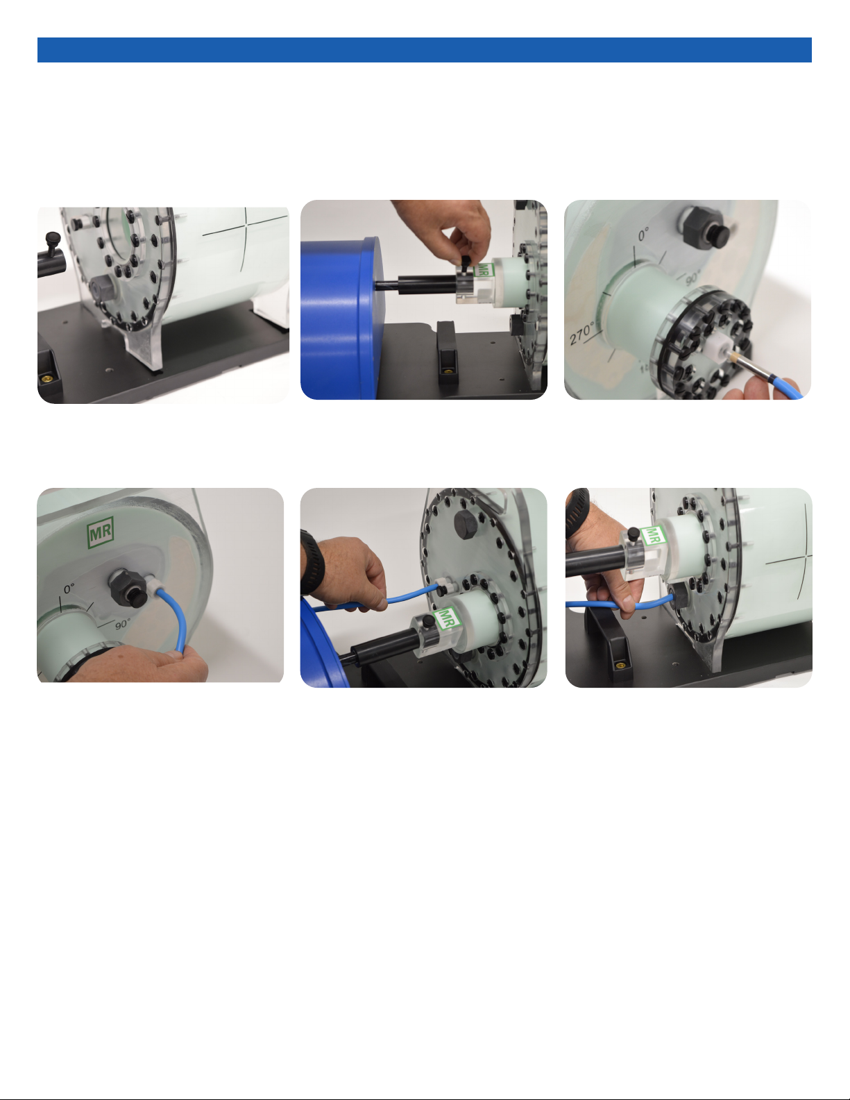
Assembly Procedure
1. Place phantom body on base plate into
the 4 slots as shown in image above. 2. Place rod into phantom body and screw
the rod and actuator together. 3. Insert ion chamber into each cavity hole.
(Moving target)
4. Insert ion chamber into each cavity hole.
(Liver) 5. Insert ion chamber into each cavity hole.
(Kidney) 6. Insert ion chamber into each cavity hole.
(Spine)
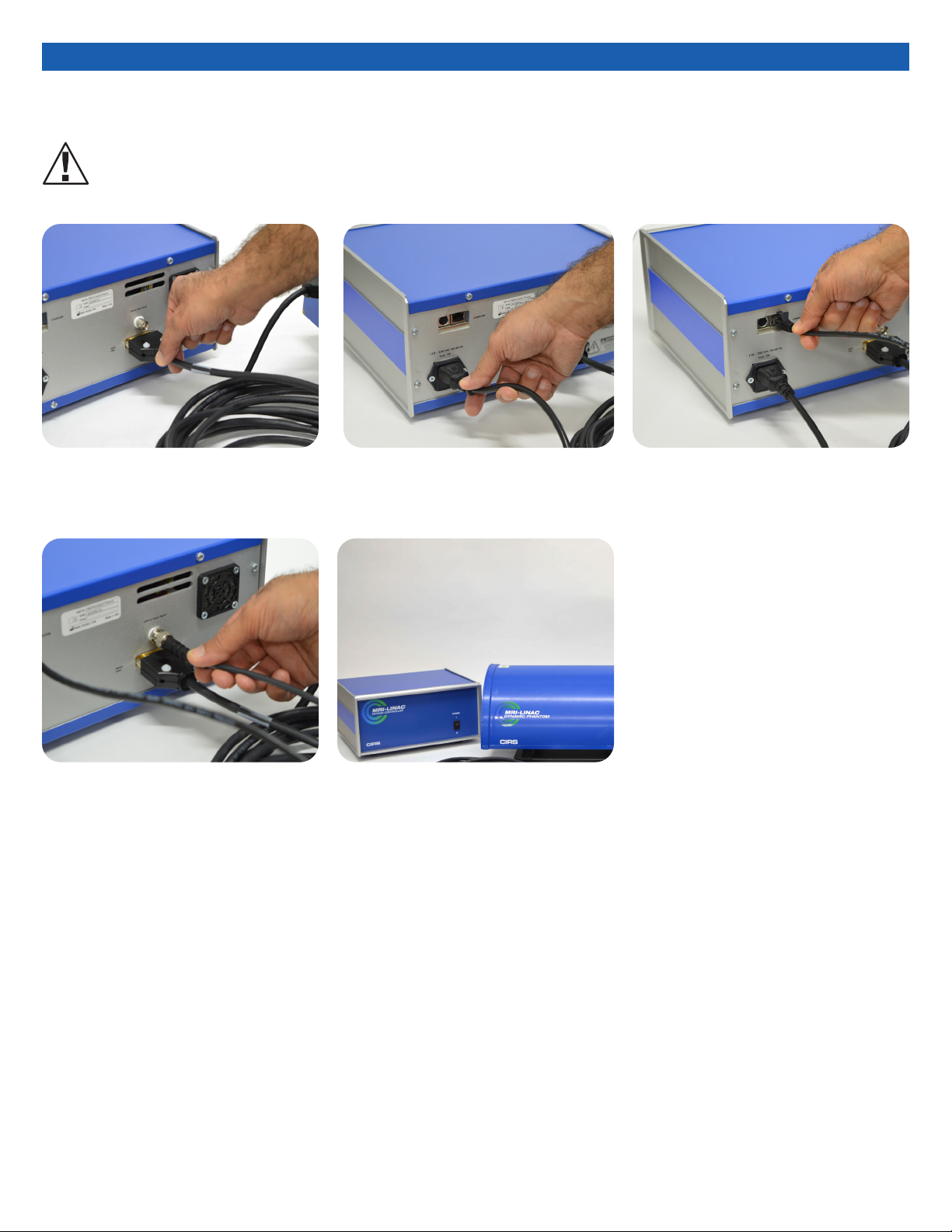
3. Attach ethernet cable to back of
controller.
2. Plug power cord into the back of
controller. Plug other end of
power cord into the wall outlet.
1. Plug the Cable DB26 m/m to back of
controller and to back of actuator.
5. The controller and actuator powered
and ready for use.
4. Plug beam latency (BNC) cable into the
back of the controller. To perform beam
latency, connect the other end of the
BNC cable to the Beam-on Beam-off
output signal of the MRI-LINAC
Cables and Connections
WARNING:
FOLLOW THE CABLE CONNECTION STEPS AS THEY ARE PRESENTED IN THIS USER GUIDE.
CONNECTING THE CABLES WITH THE CONTROLLER “POWER ON” CAN SERIOUSLY DAMAGE THE PHANTOM’S ELECTRONICS.
8
The following are the recommended steps to install the “USB to Network Adapter” that was shipped with this phantom. The new Net-
work Connection must be setup as a Static IP address in order for the PC to communicate with the motion controller of the phantom.
Setup notes for Dynamic Phantoms with controller
connecting to a PC using an Ethernet connection:
Note: The provided “USB to Network Adapter” can act as Plug and
Play device on some PC but CIRS recommends doing the installation
of the driver as outlined above.
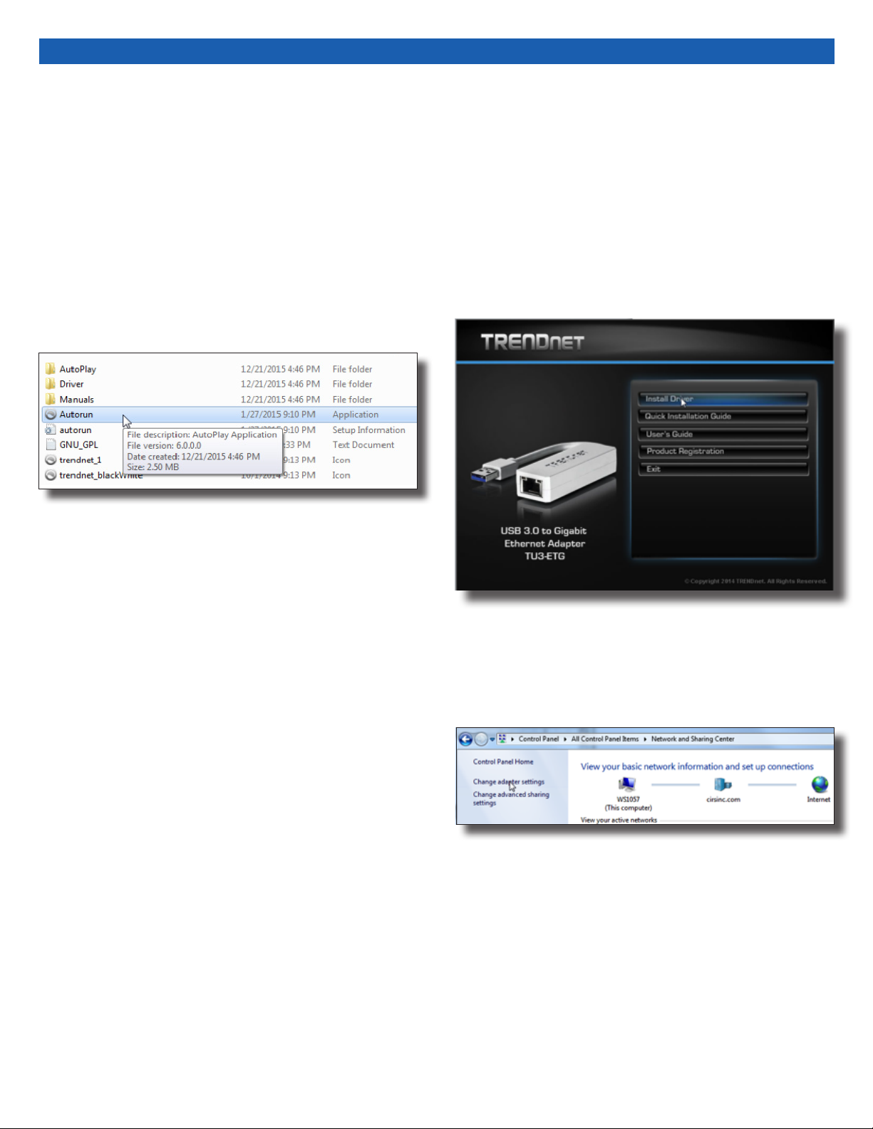
1. To install the necessary driver, unzip the “USB-to-Network
Adapter” folder found on the provided USB drive or download
the zipped folder from the CIRS website. Archive to a known
location and select autorun.
3. Follow the on screen steps and acknowledge all the mes-
sages related to driver’s installation. Once the driver installa-
tion is nished, plug the “USB-to-Network Adapter” into
your PC’s USB port and acknowledge the Windows installa-
tion message. Exit the “USB-to-Network Adapter Software”
menu by clicking Exit.
4. From the Control Panel, open the Network and Sharing Cen-
ter and then select “Change adapter settings”.
2. Let your Windows OS select the most appropriate driver by
selecting “Install Driver”.

9
6. Select Internet Protocol Version 4 (TCP/IPv4) and click on prop-
erties
5. Providing that the installation of the “USB-to-Network Card”
was successful, the newly installed Network Adapter should
show as “ASIX AX88179 USB 3.0 to Gigabit Ethernet Adapter”.
Select it’s Properties using the right mouse click menu as
shown below.
7. In the internet Protocol Version 4 (TCP/IPv4) properties window,
change from default “Obtain an IP address automatically” to
“Use the following IP address:” Enter “192.168.0.101” as the
IP address and “255.255.255.000” as the Subnet mask.
Note: If an IP address conict occurs because IP address
192.168.0.101 is already assigned to another Net
work Adapter, the user can try any other IP address between
192.168.0.102 and 192.168.0.249.
8. Once the IP address is entered, click OK. Connect the PC to
the Controller using the provided Ethernet cable by inserting
one end of the cable in the controller’s Ethernet port and the
other one in the “USB-to-Network Adapter”. Power on the
controller. To check that the PC to controller connection was
successful, ensure the icon of the “ASIX AX88179 USB 3.0 to
Gigabit Ethernet Adapter” in the Control Panel matches the
image below. Network Connection can be renamed using the
right mouse click menu.
9. A more in depth check of the PC-to-controller communication
connection can be done by running a “ping command” in Com-
mand Prompt as seen in the image below. To ping the controller,
type “ping 192.168.0.250” and press enter. Ping certies
IP-level connectivity to another TCP/IP device. If you receive
Ping statistics for IP address 192.168.0.250 (controller IP ad-
dress) the communication connection between the PC and
controller was successful.
10
CIRS MOTION CONTROL SOFTWARE SYSTEM
REQUIREMENTS
Windows XP® / Vista / Windows 7/ Windows 8/ Windows 10
(32 and 64 Bit)
Pentium 3® or equivalent
512 MB RAM, 2 MB of available disk space
INTRODUCTION
CIRS Motion Control is an application which allows you to control
the movement of the CIRS Model 008Z MrgRT Motion Management
Phantom and model 008PL Dynamic Platform. With CIRS Motion
Control, you can quickly set up a movement based on a library of
pre-dened motions, including Sin, Cos4, Cos6, Sawtooth, Shark-
n, Hysteresis ( Model 008A only) and Continuous Drift, Transient
Excursion, Persistent Excursion, High-Frequency Excursion, or you
can import custom motion data from any tab-delimited or comma-
separated text le. CIRS Motion Control also allows you to save any
motion to easily access the same parameters for repeated calibra-
tion and testing.
INSTALLATION
The CIRS Motion Control application requires the Trio PC Motion
library, which allows the computer to recognize the Trio controller
board in the Dynamic Phantom or Platform. To install the Trio PC
Motion library, double-click Trio_PC_Motion_ActiveX_2_6_15_Setup
and follow the steps in the InstallShield Wizard.
To install CIRS Motion Control, double-click MotionControl-
Setup or Setup and follow the steps in the Setup Wizard. The
Microsoft.NET Framework Version 3.5 is required for the ap-
plication to run.
GENERAL USE
The CIRS Motion Control Software is preinstalled on the optional
computer. Help can be launched from Help Menu. A copy of the
software is included on a USB drive.
CIRS does not support 3rd party equipment. Please refer to the
included documents for warranty and service information for the
ACER brand computer (computer optional).
The software automatically creates a log le where data about wave-
form parameters are saved. The log le is usually located under the
current user in the Application Data folder. A Windows OS search
function can be used to nd the log le. Searching hidden les and
folders should be enabled.
The log le provides a record of the motion history of the device and
can be used as objective evidence that proper QA was performed.
CIRS Motion Control Software
SOFTWARE USER MANUAL & SOFTWARE UPGRADES
CIRS Motion Control software has an online user manual. After
software installation, a copy may be viewed and downloaded using
either the “Check for Updates” button from Help Menu and selecting
“Motion Control User Manual.pdf” or by pointing a web browser to
the CIRS Software Updates webpage: http://www.cirsinc.com/Mo-
tionControlUpdates/Motion_Control_User_Manual.pdf
If the end-user is ofine during use of the phantom, it is recom-
mended that a copy of the CIRS Motion Control User Manual is
downloaded and saved. Once a copy of the manual is saved in a
known location, the PDF document can be opened and viewed in a
window separate from the CIRS Motion Control software window to
aid in phantom set up and use.
The user manual is regularly updated to incorporate new information
based on the addition and/or modication of features as well as end-
user feedback.
CIRS recommends that the end-user routinely check the CIRS Soft-
ware Update webpage using the “Check for Updates” button from
Help Menu. This page indicates the current software version. The
latest free software upgrade is posted as soon as it becomes avail-
able. Instructions for updating the software are also posted.
BEAM LATENCY TESTING
For recommended procedures on how to perform beam latency
testing, refer to the CIRS Motion Control User Manual which can be
launched from the help menu.

11
Model 008Z Specications
INCLUDED WITH MODEL 008Z
Note: Customers must complete their order with the purchase of the moving rod. *Refer to
separate CIRS cavity code list for available chamber cavities. It is recommended to choose
the same cavities for both the body and rod.
Part No. Qty Component Description
008Z 1 MRgRT Motion Management QA phantom Body
(moving rod not included )
1 Dynamic Motion Controller with rmware
installed (110 - 220V, 50 - 60Hz)
1 Actuator base plate assembly
1 CIRS Motion Control Software
1 Communication cables kit: Ethernet cable +
adapter
1 User’s guide
2 Carry Case
OVERALL DIMENSIONS: 67 cm x 32 cm x 20 cm
OVERALL WEIGHT: 12 kg (26.5 lbs)
AMPLITUDE, IS: ± 25 mm
AMPLITUDE, AP/LR: ± 3.5 mm
MOTION ACCURACY: ± 0.2 mm (linear motion)
MOTION ACCURACY: ± 0.25o (rotation motion)
CYCLE TIME: 1 - ∞ (adjusted based on amplitude)
WAVEFORMS: sin (t), 1-2cos4(t), 1-2cos6(t), sawtooth, sharkn (built in),
custom (through import)
OVERALL DIMENSIONS: 25.6 cm x 32 cm x 18 cm
OVERALL WEIGHT: 10 kg (22 lbs)
MOTION CONTROLLER
PHANTOM BODY*
OVERALL DIMENSIONS: 22 cm x Ø 6.3 cm
OVERALL WEIGHT: 1.1 kg (2.4 lbs)
MOVING ROD*

12
All standard CIRS products and accessories are warranted by CIRS
against defects in material and workmanship for a period as speci-
ed below. During the warranty period, the manufacturer will repair
or, at its option, replace, at no charge, a product containing such
defect provided it is returned, transportation prepaid, to the manu-
facturer. Products repaired in warranty will be returned transportation
prepaid.
There are no warranties, expressed or implied, including without
limitation any implied warranty of merchantability or tness, which
extend beyond the description on the face hereof. This expressed
warranty excludes coverage of, and does not provide relief for,
incidental or consequential damages of any kind or nature, includ-
ing but not limited to loss of use, loss of sales or inconvenience. The
exclusive remedy of the purchaser is limited to repair, recalibration,
or replacement of the product at manufacturer’s option.
This warranty does not apply if the product, as determined by the
manufacturer, is defective because of normal wear, accident, mis-
use, or modication.
NON-WARRANTY SERVICE
If repairs or replacement not covered by this warranty are required, a
repair estimate will be submitted for approval before proceeding with
said repair or replacement.
PRODUCT WARRANTY PERIOD
Model 008Z- MRgRT Motion
Management QA Phantom and
accessories
24 Months
Warranty
RETURNS
If you are not satisfied with your purchase for any reason, please
contact your local distributor prior to returning the product. Visit
https://www.cirsinc.com/distributors/ to find your local distributor. If
you purchased your product direct through CIRS, call Customer
Service at 800-617-1177, email [email protected], or fax an RMA
request form to 757-857-0523. CIRS staff will attempt to remedy
the issue via phone or email as soon as possible. If unable to correct
the problem, a return material authorization (RMA) number will be
issued. Non-standard or “customized” products may not be
returned for refund or exchange unless such product is deemed by
CIRS not to comply with documented order specifications. You
must return the product to CIRS within 30 calendar days of the issu-
ance of the RMA. All returns should be packed in the original cases
and or packaging and must include any accessories, manuals and
documentation that shipped with the product. The RMA number
must be clearly indicated on the outside of each returned package.
CIRS recommends that you use a carrier that offers shipment
tracking for all returns and insure the full value of your package so
that you are completely protected if the shipment is lost or damaged
in transit. If you choose not to use a carrier that offers tracking or
insure the product, you will be responsible for any loss or damage to
the product during shipping. CIRS will not be responsible for lost or
damaged return shipments. Return freight and insurance is to be
pre-paid.
With RMA number, items may be returned to:
CIRS
Receiving
900 Asbury Ave,
Norfolk, Virginia, 23513 USA

13
NOTES:

14
NOTES:

15
NOTES:

©2019 Computerized Imaging Reference Systems, Inc. All rights
reserved.
All brand names, product names or trademarks belong to
their respective holders.
Specifications subject to change without notice.
Publication: 008Z UG 110320
Computerized Imaging Reference Systems, Inc. has
been certied by UL DQS Inc. to (ISO) 13485:2016.
Certicate Registration No.10000905-MP2016.
COMPUTERIZED IMAGING
REFERENCE SYSTEMS, INC.
900 Asbury Ave
Norfolk, Virginia 23513 USA
Toll Free: 800.617.1177
Tel: 757.855.2765
Fax: 757.857.0523
Email [email protected]
www.cirsinc.com
Technical Assistance
1.800.617.1177
Table of contents
Other Cirs Industrial Equipment manuals


Popular Industrial Equipment manuals by other brands

SCHUNK
SCHUNK VERO-S NSR mikro 60 Assembly and operating manual

Holmatro
Holmatro HGC C Series manual

Mayr
Mayr EAS-compact 493. 4 .0 Series Installation and operating instructions

PCB Piezotronics
PCB Piezotronics 084A17 Installation and operating manual

Dixon
Dixon Bayco Maintenance & Operating Instructions

Tektronix
Tektronix 7000-series instruction manual


KTR-Group
KTR-Group KTR-STOP L light A Series Operating & assembly instructions

Vahle
Vahle VKS Series Mounting instructions - Maintenance

Trak Machine Tools
Trak Machine Tools TMC5 manual

Axis
Axis CHAMPGYRO quick start guide

Dometic
Dometic SMX II Description and installation manual

Texas Instruments
Texas Instruments DRV2604LDGS user guide