Cirs Doppler String Phantom 043 User manual

900 Asbury Ave • Norfolk, Virginia 23513 • USA • Tel: 757-855-2765 • WWW.CIRSINC.COM
USER GUIDE
Doppler String Phantom
Model 043


Table of Contents
OVERVIEW ......................................................................................................................................................... 1
Features of the Doppler String Phantom .............................................................................................................. 1
Starting a Quality Assurance Program ................................................................................................................. 1
SETUP INSTRUCTIONS ..................................................................................................................................... 2
Parts List ............................................................................................................................................................. 2
Using the Diffuser Mat ......................................................................................................................................... 3
Installing the String .............................................................................................................................................. 3
Filling the Tank..................................................................................................................................................... 3
Setting up the Clamp........................................................................................................................................... 4
Connecting the Controller.................................................................................................................................... 5
SPECIAL FEATURE
Using The ECG Output ....................................................................................................................................... 5
OPERATING INSTRUCTIONS ............................................................................................................................ 6
Using Constant Speeds....................................................................................................................................... 6
Using Preprogrammed Waveforms ...................................................................................................................... 6
RS-232 INSTRUCTIONS .................................................................................................................................. 7
Introduction ......................................................................................................................................................... 7
Getting Started.................................................................................................................................................... 7
Accessing the Help Menu.................................................................................................................................... 8
Selecting Velocities and Waveforms..................................................................................................................... 9
Setting Up for Quality Control Testing .................................................................................................................. 9
Locking the Settings.......................................................................................................................................... 10
Description of Commands Available Via RS-232................................................................................................ 10
MAINTENANCE INSTRUCTIONS ................................................................................................................... 11
Making String Loops ......................................................................................................................................... 11
Ordering String Loops ...................................................................................................................................... 11
Cleaning the Doppler String phantom ............................................................................................................... 11
Calibrating the Doppler String Phantom............................................................................................................. 11
Replacing a fuse................................................................................................................................................ 12
ACCESSORIES AND PARTS............................................................................................................................ 12
Carrying Case.................................................................................................................................................... 12
Preformed String Loops..................................................................................................................................... 12
Step Up and Down Transformer ........................................................................................................................ 12
WARRANTY ..................................................................................................................................................... 13
Non-Warranty Service........................................................................................................................................ 13
APPENDIX A GRAPHS OF WAVEFORMS....................................................................................................... 14
Test Waveforms................................................................................................................................................. 14
Physiological Waveforms ................................................................................................................................... 19
APPENDIX B SAMPLE QA FORM .................................................................................................................. 26

1
OVERVIEW
Features of the Doppler String Phantom
The Doppler String phantom is a very accurate device for testing Doppler ultrasound scanners. It is especially
useful for checking sample volume registration, color registration, directional discrimination, and Doppler velocity
accuracy.
The Doppler String Phantom offers superior accuracy by using a string target that never changes (unlike sus-
pended scatterers in fluid flow phantoms) and a crystal-controlled motor. The motor speed is adjusted 1000
times per second, allowing realistic reproductions of human blood flow velocity patterns and a wide range of con-
stant velocities.
The Doppler String Phantom has been designed for ease of use. It can be set up quickly and easily with ordinary
tap water. It is simple to use and almost no maintenance is required. An RS-232 interface is also provided for
automated use, if desired. Ultrasound technologists, biomedical technicians, researchers and manufacturers all
rely on the Doppler String Phantom for hassle-free, reliable testing.
Starting a Quality Assurance Program
Each ultrasound lab will have different Quality Assurance (QA) needs depending on equipment, maintenance
agreements and applicable laws and policies. However, many technicians recommend performing QA tests
every 3 months. Of course, any time you suspect a problem with an ultrasound scanner, you will want to test it
immediately.
CIRS recommends using a standard form to record the results of your tests, so you can be sure that each testing
session is consistent and thorough. Recording your findings also provides written documentation of your QA
program. A sample QA form is provided in Appendix B of this User Guide.
2
SETUP INSTRUCTIONS
Parts List
When you unpack the Doppler String Phantom for the first time, you should find:
• Electronic Controller
• Acrylic tank with motor and pulleys attached
• Scanhead Clamp
• Set of 5 String Loops (not pictured)
• Rubber Diffuser Mat (not pictured)
• Power Cord (not pictured)
• Carrying Case (not pictured)
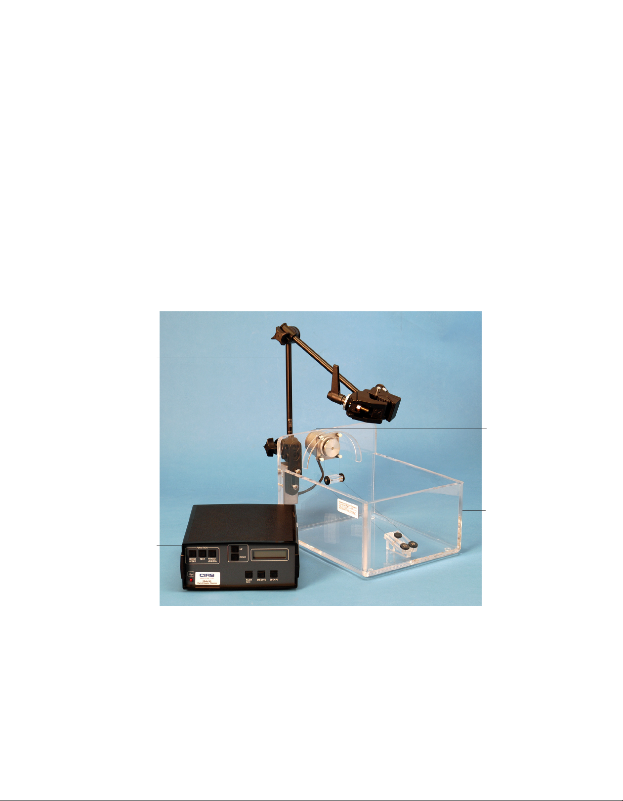
Figure 1: Doppler String Phantom
Electronic
Controller
Scanhead Clamp
Motor
Acrylic Tank

3
Using the Diffuser Mat
The black rubber Diffuser Mat is provided to reduce reverberations in the tank by absorbing and scattering the
ultrasound beam. Place the mat in the bottom of the tank with the ridges facing up, if desired.
Installing the String
If your Doppler String Phantom was shipped in a custom carrying case, the string target is already installed. If
not, you will need to install the string by doing the following:
1. Loosen the adjusting screw on the two pulleys at the end of the tank opposite
the motor.
2. Take one of the string loops out of the bag and lay it over the pulley that is
attached directly to the motor (Motor Pulley).
3. Draw the string half-way around the Motor Pulley, behind the two Idler Pulleys
below the motor, and around the pair of Adjustable Pulleys at the other end of
the tank. (See Figure 2).
4. Adjusting the string tension by moving the Adjustable Pulleys until the string is
fairly tight, but not tight enough to break. The actual tension will not affect the
data.
Figure 2: String Installation
About Reverberations:
Water conducts ultrasound
more efficiently than the
human body, so it may be
necessary to reduce the
power level on your ultra-
sound scanner to a mini-
mum for best results.
FILLING THE TANK
Place the tank on a firm surface and fill it with either cold tap water or velocity-corrected fluid (see sidebar).
Fill the tank until the two small pulleys beneath the motor are just submerged. This depth works well, but it may
be changed to meet your needs.
After filling the tank, there will be dissolved air bubbles in the water. For best results, wait an hour before using
the Doppler String Phantom so the water can de-gas.

4
Setting up the Clamp
The Doppler String Phantom is shipped with a scanhead clamp system con-
sisting of a clamp (see Figure 3), an "arm" with a center joint and an arm at-
tachment fixture, which is bolted to the tank. If your Doppler String Phantom
was shipped in a custom carrying case, the clamp will have been set up at the
factory and you should skip step 1.
1. The arm attachment fixture on the tank has two sockets.
Insert one end of the arm into either of the sockets and tighten the
thumbscrew.
2. Turn the clamp adjusting knob to open or close the clamp so that it
fits your scanhead.
3. Adjust the clamp and articulated arm so that the transducer end of the
scanhead is in the water. (See Figure 4). Make sure your scanhead is at the
desired angle with respect to the string.
Note: Although the scanhead clamp can be placed in water temporarily, it should
be stored in a dry location to prevent corrosion.
Figure 3: Scanhead Clamp
Clamp
Adjusting
Knob
About Velocity Corrected
Fluid:
The speed of sound is 1480
meters per second in water
and 1540 meters per second
in the human body. Doppler
scanners are calibrated for
1540 meters per second, so
some ultrasound profession-
als prefer to use a water/gly-
col mix that also has a speed
of sound of 1540 meters per
second. This mix is called
velocity corrected fluid.
The Doppler String Phantom
has been designed to work
with either plain water or
velocity-corrected fluid (H2O/
Glycol). When you turn on
the power, the Doppler String
Phantom will ask you which
type of fluid you are using.
When set for use with water,
the Doppler String Phantom
compensates for the different
speed of sound by adjust-
ing the speed of the string
and the display indicates the
speed your scanner should
be detecting. When set for
use with velocity-corrected
fluid, the Doppler String Phan-
tom moves the string at the
actual speed indicated on the
display.

5
Connecting the Controller
You are now ready to connect the controller to the motor and the power supply.
1. Before plugging in the controller make sure the power switch on the back is turned off.
2. Plug the motor cable into the Drive Motor receptacle on the back of the controller.
3. Plug the power cable into the AC Receptacle and into an AC power source. If using in a country other than
the United States you will need to connect the transformer as well. This can be purchased for an additional
price.
SPECIAL FEATURE
Using the ECG Output
The ECG (electrocardiogram) output is an output that the user can elect to use to synchronize the waveforms to
the ultrasound scanner. It is located on the rear panel of the phantom. This is a rarely used feature that can aid
ultrasound researchers as they test new ultrasound machines. Since most users of this phantom do not deal
with that aspect it may be simply ignored.
When used, this output will generate a signal pulse at the very beginning of each test or physiological waveform.
That pulse is 10 milliseconds long and rises from zero volts up to five volts and then back down. This may be
used to tell the ultrasound researcher exactly when the waveform started and is useful for internal adjustments to
the ultrasound scanner.
Figure 4: Scanhead clamp and articulated arm
About Scanning Angles:
The best angle for most Doppler
ultrasound scans is 60°.
The string target in the
Doppler String Phantom is set
at an angle, so that a scanhead
aimed straight down will be at
a 60° angle to the string. Of
course, you should scan at the
angle that is needed for your
tests.

6
OPERATING INSTRUCTIONS
Using Constant Speeds
The Doppler String Phantom can be set for constant string speeds ranging from 20 to 200 cm/sec. Constant
speeds are useful for a quick check to verify that your scanner is reporting correct image registration and target
velocity for the scanning angle you’re using. You can also detect false data caused by a broken transducer or a
loose connection.
1. After setting up the Doppler String Phantom, turn on the power switch (located on the back of the controller).
The display reads UP=H2O DOWN=H2O/GLYCOL.
2. If the tank is filled with water, press UP. If the tank is filled with velocity-corrected fluid, press DOWN.
(See About Velocity-Corrected Fluid on page 4 for more information.)
The display reads SELECT A FUNCTION.
3. Press CONST. SPEED; then press UP or DOWN to select the desired speed.
Note: Holding down either the UP or DOWN button causes the display to scroll faster.
The motor starts automatically.
4. To reverse the direction of simulated flow, press FLOW REV at any time.
An arrow in the bottom right corner of the display indicates the flow direction.
5. To change functions (for example, to switch from constant speeds to test waveforms), press ESCAPE.
The display reads SELECT A FUNCTION.
Using Preprogrammed Waveforms
The Doppler String Phantom has several preprogrammed waveforms to help you test your ultrasound scanner
under realistic conditions with velocity fluctuations you might expect in a patient. Each waveform has 1000 data
points to provide accurate simulations. The waveforms are divided into two groups: test waveforms and physi-
ological waveforms. Graphs of all the waveforms are included in Appendix A of this User's Guide.
The test waveforms are:
• Sine waves with peak speeds of 100, 150, and 200 cm/sec
• Triangle waves with peak speeds of 100, 150, and 200 cm/sec
• Stepped ramp wave with stops at 1, 20, 40, 60, 80, and 100 cm/sec
The physiological waveforms are:
• Adult common carotid
• Adult aortic
• Adult femoral
• Pediatric umbilical
• Stenotic common carotid
• Pediatric renal
• Pediatric ductus arteriosus
• Pediatric middle cerebral
• Pediatric descending thoracic

7
After setting up the Doppler String Phantom, turn on the power switch (located on the back of the controller).
The display reads UP=H2O DOWN=H2O/GLYCOL.
1. If the tank is filled with water, press UP. If the tank is filled with velocity-corrected fluid, press DOWN.
(See About Velocity-Corrected Fluid on page 4 for more information.)
The display reads SELECT A FUNCTION.
2. Press TEST or PHYSIOLOGICAL to select a waveform group.
The display shows a waveform.
3. Press UP or DOWN to select a waveform. (See Appendix A for graphs of waveforms.)
4. Press EXECUTE to start the motor.
5. To select a different waveform, you may press UP or DOWN at any time while the motor is running.
6. To reverse the direction of simulated flow, press FLOW REV at any time.
An arrow in the bottom right corner of the display indicates the flow direction.
7. To change functions (for example, to switch from physiological waveforms to constant speeds), press
ESCAPE. The display reads SELECT A FUNCTION.
RS-232 INSTRUCTIONS
Introduction
The remote control software allows all of the same functions that are available from the front panel. It is primarily
a serial communications feature for use with automatic testing equipment, but may be used by anyone wanting
to control the phantom for standardized testing. It may be controlled by a laptop, desktop, or a process control
computer.
To establish the link between the Doppler String Phantom controller and your computer, any common RS-232
communications program such as Pro-Comm Plus, Teraterm Plus, Microsoft Hyperterminal, etc., may be used.
The communications program must be set to 9600, N, 8, 1. Use hardware flow control. If your computer does
not have an RS-232 port, you can use an adapter available locally that will convert a standard USB port to RS-
232.
Getting Started
To begin using the remote control feature:
1. Ensure the Doppler String Phantom controller is powered off (rear panel switch).
2. Plug the power cable into the AC Receptacle and into an AC power source. The label on the AC
Receptacle indicates 120 volts. If using with 220 volts, use step down controller (Model 901-C, sold sepa-
rately).
3. Plug the custom RS-232 cord (supplied with the Doppler String Phantom) into the RS-232 receptacle
on the back of the controller.
4. Plug the motor cable into the Drive Motor receptacle on the back of the controller.
5. Start the communications program.
6. Turn on the power on the controller (rear panel switch).

8
The following text should appear on your computer screen:
MARK 4 DOPPLER PHANTOM
MARK 4 MENU
C - CONSTANT SPEED
S - SET CONSTANT SPEED, CM/S
T - TEST WAVES
P - PHYSIOLOGICAL WAVES
U - UP KEY
D - DOWN KEY
E - EXECUTE KEY
Enter - EXECUTE KEY
R - REVERSE FLOW
Esc - ESCAPE KEY
^H - COMMAND MENU
^Z - RESTART PROGRAM
^L - LOCKOUT FRONT PANEL KEYS
^U - UNLOCK FRONT PANEL KEYS
SELECT H2O OR H20/GLYCOL
FOR THE FLUID IN THE TANK
UP= H20 DOWN=H20/GLYCOL
*
If this text does not appear check all connections and try again. When the text appears the system is ready to test.
Notes: When entering commands either upper or lower case may be used. Upper case is used in this manual for easier
reading. Between each command wait until the controller responds that it's ready for the next command.
Accessing the Help Menu
The Help Menu (shown below) can be displayed at any time by entering <Ctrl>+H. The Help Menu is also
displayed automatically upon power-up.
MARK 4 MENU
C - CONSTANT SPEED
S - SET CONSTANT SPEED, CM/S
T - TEST WAVES
P - PHYSIOLOGICAL WAVES
U - UP KEY
D - DOWN KEY
E - EXECUTE KEY
Enter - EXECUTE KEY
R - REVERSE FLOW
Esc - ESCAPE KEY
^H - COMMAND MENU
^Z - RESTART PROGRAM
^L - LOCKOUT FRONT PANEL KEYS
^U - UNLOCK FRONT PANEL KEYS

9
Selecting Velocities and Waveforms
Constant Speeds
The following example demonstrates how to generate various Doppler target velocities:
To create a constant flow at 52 cm/sec the following steps must be taken:
1. Turn the controller on or enter <Ctrl> Z to restart the program.
2. Issue Uor Dto select the type of fluid in the tank.
3. Issue Cto select Constant speeds.
4. Issue S52 to select a speed of 52 cm/sec.
Note: Only whole numbers are allowed for velocities.
Test Waveforms
To select a changing velocity profile such as a sine wave that ranges from -100 cm/sec to +100 cm/sec the fol-
lowing steps must be taken:
1. Turn the controller on or enter <Ctrl> Z to restart the program.
2. Issue Uor Dto select the type of fluid in the tank.
3. Issue Tto select Test waves. The screen displays '100 Sine'.
4. To select a different waveform issue Uto move up the list. Continue issuing Uor Duntil the desired
waveform is displayed.
5. Issue an <Enter> command to execute the selected waveform.
Human Waveforms
To select a human Doppler waveform such as the "Common Carotid' waveform the following steps must be
taken:
1. Turn the controller on or enter <Ctrl> Z to restart the program.
2. Issue Uor Dto select the type of fluid in the tank.
3. Issue Pto select Physiological waves. The screen displays 'Common Carotid'.
4. To select a different waveform issue Uto move up the list. Continue issuing Uor Duntil the desired
waveform is displayed.
5. Issue an <Enter> command to execute the selected waveform.
Flow Reversal
To reverse the flow direction of any constant speed or waveform first execute the desired speed or waveform
and then issue an R. The target string will stop and then accelerate up to the desired speed or waveform in the
opposite direction.
Setting up for Quality Control Testing
The following example demonstrates how to test ultrasound machines for Doppler accuracy at 100 cm/sec at
the end of the manufacturing process.
1. Insert the ultrasound machine’s probe into the holder on the tank.
2. Prepare the ultrasound machine to send Doppler data to the process controller machine. Enter the
insonation angle to the process controller if not already done.
3. Turn on the Doppler phantom or issue a cold start with <Ctrl> Z.

10
4. Issue the following commands:
U
C (motor starts at 10 cm/sec)
S100
<Enter>.
5. The controller will increase the velocity from the initial 10 cm/sec to 100 cm/sec and hold. Read in the velocity
data from ultrasound machine and compare to the phantom. This completes the procedure.
Locking the Settings:
To prevent the phantom settings from being changed at the front panel while operating via remote control, issue
a <Ctrl> L command from the remote computer. To unlock the settings, issue a <Ctrl> U command. Unlocked
mode is the default setting at startup and after restarting with <Ctrl> Z.
Description of Commands Available Via RS-232
CCONSTANT SPEED Used to select constant velocity. Velocities must be
whole numbers; decimal numbers are not allowed.
SSET CONSTANT SPEED, CM/S Used only when controller is already in constant speed
mode. Issue an S command followed immediately by
a whole number between 10 and 200, for example
S52<Enter>. Decimal numbers are not allowed.
TTEST WAVES Used to access test waveforms.
PPHYSIOLOGICAL WAVES Used to access physiological waveforms.
UUP KEY Used to select water type in tank, move up in the
menus and to increase constant speeds.
DDOWN KEY Used to select water type in tank, move down in the
menus and to decrease constant speeds.
EEXECUTE KEY Used to select options currently displayed.
<Enter> Same as EXECUTE button.
RREVERSE FLOW Used to reverse the direction of the Doppler target
string in all modes.
Esc ESCAPE KEY Used to shut down motor driving the Doppler target
string and go back to basic mode selection.
^H HELP MENU Used to display the list of available commands.
^Z RESTART PROGRAM Used to cancel and clear all entries and start over.
This is equivalent to dropping power to the unit and
turning it back on.
^L LOCK OUT FRONT PANEL
KEYS
Used to block all commands from front panel of con-
troller. While in Lockout mode all buttons are ignored.
^U UNLOCK FRONT PANEL KEYS Used to allow commands to be entered from the
front panel of the controller. This is the default startup
condition.

11
MAINTENANCE INSTRUCTIONS
Making String Loops
Occasionally, string loops break and need to be replaced. You can order sets of 20 preformed loops from CIRS
(See Preformed String Loops for more information) or make your own loops using these instructions. In general
you want your string loop to have a small unobtrusive knot that will roll smoothly over the pulleys in the tank.
1. Set up two pins 15 3/16 inches (38.5 cm) apart. Push pins on a wooden measuring stick works well.
2. Form a loop of string around the pins. Any type of string will work but 3-0 surgical silk is recommended
because of its ultrasound scattering properties.
3. Tie a knot to secure the loop and trim the ends to about 1/4 inch (6 mm) long.
4. Put a very small dot of super glue on the knot. The glue should not soak into the ends of the string and make
them stiff.
5. After the super glue has dried roll the ends of the string between your fingers to separate the threads as
much as possible.
6. Apply rubber cement to the knot and string ends allow it to dry slightly and then roll the knot between your
fingers to form a smooth ball.
Ordering String Loops
You can order a pack of 20 preformed string loops made from 3-0 surgical silk. The Part number is 043SL.
Please call for current prices.
Cleaning the Doppler String Phantom
The Doppler String Phantom is designed to be virtually maintenance-free. You can clean the controller and tank
with a soft cloth dampened with water and mild detergent. Do not use disinfectants or solvent-based cleaners or
sprays. Avoid using solvents because they could weaken the tank.
Calibrating the Doppler String Phantom
The Doppler String Phantom is computer-controlled so you don't need to make any adjustments. However,
many customers choose to send their Doppler String Phantom back to CIRS each year for calibration certifica-
tion. The string speeds are checked at a variety of settings, using instruments that are certified according to
the National Institute of Standards and Technology (NIST). After verifying that the Doppler String Phantom is
functioning correctly, CIRS provides a calibration certificate and a complete test report. Contact CIRS for more
information regarding calibration service.
12
ACCESSORIES AND PARTS
Carrying Case
To protect your investment, the Model 043 comes standard with a foam-lined, rigid carrying case. The case is
hermetically sealed and includes castors and a retractable handle for easy transport. The carrying case is highly
recommended for customers who plan on travelling with or shipping their Doppler String Phantom.
Preformed String Loops
You can order a pack of 20 preformed string loops made from 3-0 surgical silk. The Part number is 043SL.
Please call for current prices.
Step Up and Down Transformer
CIRS offers a 220V step up/down transformer to be used with the Doppler String Phantom, when using outside
of the USA. The Part number is 043C. Please call for current pricing.
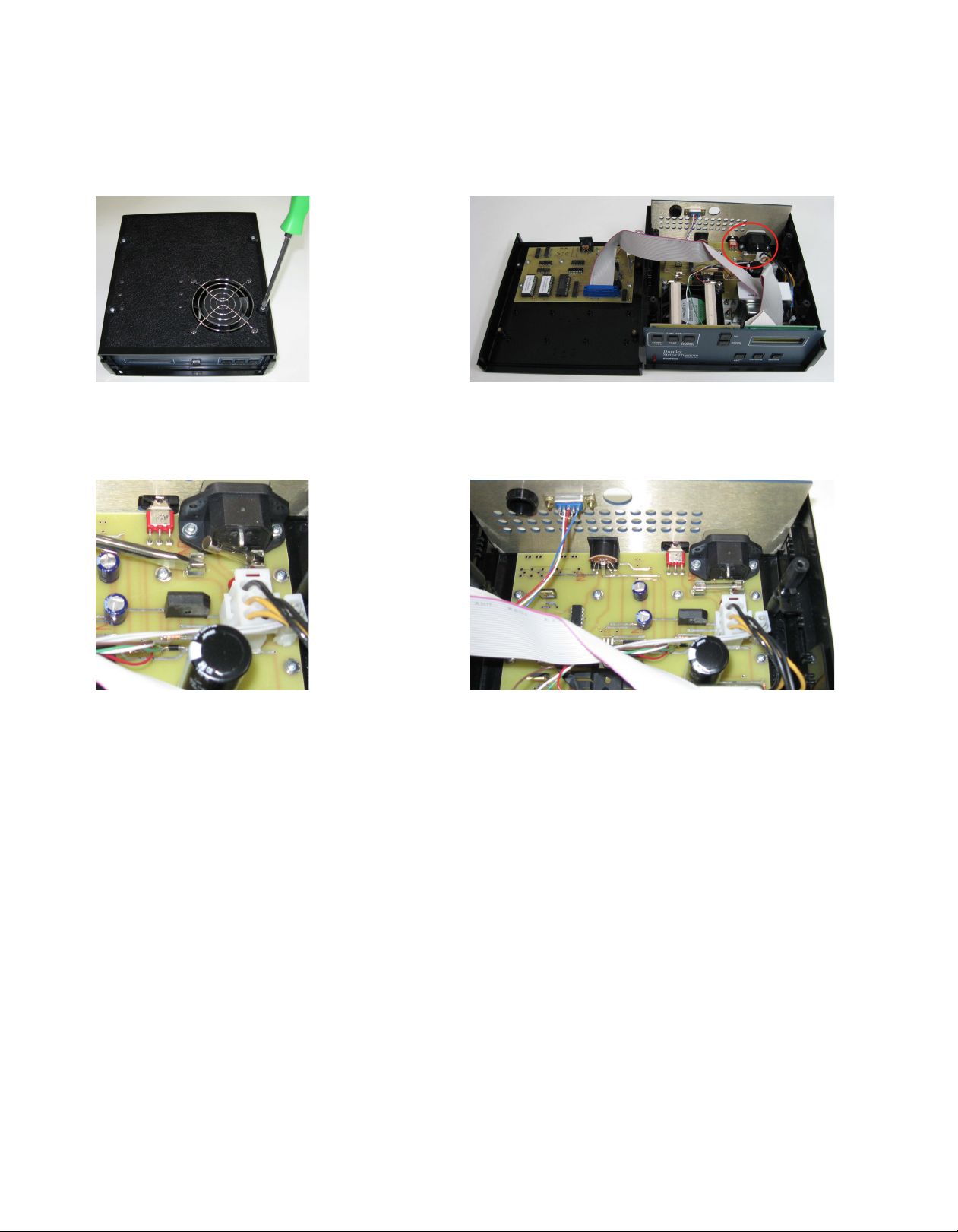
How to replace a fuse
The Doppler String Phantom contains a fuse that may need to be replaced periodically. If the unit does not
power up, first check the cord and power source. If all of the connections are properly in place then the fuse
may need to be replaced.
Unplug the unit from the power
source and locate the 4 screws
on the bottom of the controller.
Remove these screws.
Open the controller. The fuse is found in the back, right
side of the controller.
Use a screwdriver to flip up one
end of the fuse and remove it.
Replace the fuse (2A 250V). Ensure fuse is properly
seated and replace the top of the controller. Replace
the screws into the bottom of the controller.

13
WARRANTY
All standard CIRS products and accessories are warranted by CIRS against defects in material and workmanship
for a period as specified below. During the warranty period, the manufacturer will repair or, at its option, replace,
at no charge, a product containing such defect provided it is returned, transportation prepaid, to the manufac-
turer. Products repaired in warranty will be returned transportation prepaid.
There are no warranties, expressed or implied, including without limitation any implied warranty of merchantability
or fitness, which extend beyond the description on the face hereof. This expressed warranty excludes coverage
of, and does not provide relief for, incidental or consequential damages of any kind or nature, including but not
limited to loss of use, loss of sales or inconvenience. The exclusive remedy of the purchaser is limited to repair,
recalibration, or replacement of the product at manufacturer’s option.
This warranty does not apply if the product, as determined by the manufacturer,
is defective because of normal wear, accident, misuse, or modification.
Non-Warranty Service
If repairs or replacement not covered by this warranty are required, a repair estimate will be submitted for ap-
proval before proceeding with said repair or replacement.
Returns
If you are not satisfied with your purchase for any reason, please contact your local distributor prior to returning
the product. Visit https://www.cirsinc.com/distributors/ to find your local distributor. If you purchased your
product direct through CIRS, call Customer Service at 800-617-1177, email [email protected], or fax an RMA
request form to 757-857-0523. CIRS staff will attempt to remedy the issue via phone or email as soon as
possible. If unable to correct the problem, a return material authorization (RMA) number will be issued. Non-
standard or “customized” products may not be returned for refund or exchange unless such product is deemed
by CIRS not to comply with documented order specifications. You must return the product to CIRS within 30
calendar days of the issuance of the RMA. All returns should be packed in the original cases and or packaging
and must include any accessories, manuals and documentation that shipped with the product. The RMA number
must be clearly indicated on the outside of each returned package. CIRS recommends that you use a carrier that
offers shipment tracking for all returns and insure the full value of your package so that you are completely
protected if the shipment is lost or damaged in transit. If you choose not to use a carrier that offers tracking or
insure the product, you will be responsible for any loss or damage to the product during shipping. CIRS will not
be responsible for lost or damaged return shipments. Return freight and insurance is to be pre-paid.
With RMA number, items may be returned to:
CIRS
Receiving
900 Asbury Ave,
Norfolk, Virginia, 23513 USA
Product Warranty Period
Model 043 - Doppler String Phantom 24 Months

14
APPENDIX A - GRAPHS OF WAVEFORMS
TEST WAVEFORMS
Sine Wave, 100 cm/sec

15
APPENDIX A - GRAPHS OF WAVEFORMS
Sine Wave, 150 cm/sec

16
Sine Wave, 200 cm/sec
APPENDIX A - GRAPHS OF WAVEFORMS
17
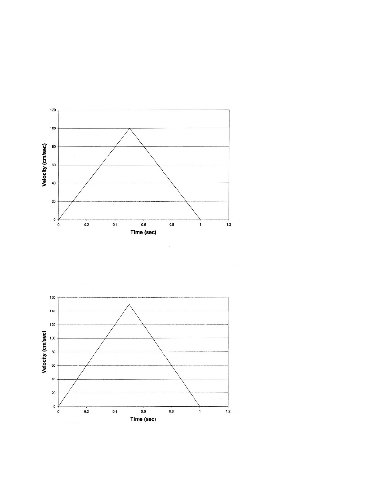
Triangle Wave, 100 cm/sec
Triangle Wave, 150 cm/sec
APPENDIX A - GRAPHS OF WAVEFORMS
Table of contents
Other Cirs Industrial Equipment manuals


