Cirs 054GS User manual
ZERDINE®
Inside
A registered trademark of CIRS
USER GUIDE
U
L
T
R
A
S
O
U
N
D
Q
U
A
L
I
T
Y
A
S
S
U
R
A
N
C
E
General Purpose
Ultrasound Phantom
Model 054GS
900 Asbury Ave • Norfolk, Virginia 23513 • USA • Tel: 757-855-2765 • WWW.CIRSINC.COM

TABLE OF CONTENTS
1 OVERVIEW
1
2 INSTRUCTIONS FOR USE
2
HANDLING AND CARE
��������������������������������������������������������������� 2
USE OF REMOVABLE WATER WELL AND COVERS
������������������������������������ 3
GENERAL GUIDELINES FOR PERFORMING MEASUREMENTS
������������������������� 4
ESTABLISHING A BASELINE
��������������������������������������������������������� 4
3 TESTING PROCEDURES
5
UNIFORMITY TESTING
��������������������������������������������������������������� 5
DEPTH OF PENETRATION
������������������������������������������������������������ 6
BEAM PROFILE/FOCAL ZONE/LATERAL RESPONSE WIDTH
��������������������������� 7
VERTICAL DISTANCE MEASUREMENT
������������������������������������������������ 7
HORIZONTAL DISTANCE MEASUREMENT
��������������������������������������������� 8
AXIAL AND LATERAL RESOLUTION
��������������������������������������������������� 8
ELEVATIONAL RESOLUTION
��������������������������������������������������������� 10
LOW-CONTRAST TARGET DETECTABILITY
������������������������������������������� 11
GRAYSCALE CONTRAST SENSITIVITY
����������������������������������������������� 11
DEAD ZONE ASSESSMENT
���������������������������������������������������������� 12
4 SPECIFICATIONS
13
5 ZERDINE®
15
6 WARRANTY
16
7 APPENDIX: QUALITY ASSURANCE RECORD FOR MODEL 054GS
17

1
OVERVIEW
The Model 054GS General Purpose
Ultrasound Phantom is a sturdy, reli-
able phantom for testing the imaging
performance of ultrasonic systems.
The phantom is made of CIRS'
proprietary Zerdine®hydrogel poly-
mer, which has been formulated to
provide tissue mimicking properties
including compatibility with harmonic
imaging. To maximize phantom
lifetime, this gel is contained in a
rugged ABS plastic housing with a
Saran-based laminate membrane.
CIRS is certified to ISO 9001:2008
standards. We have an in-house
test facility to measure acoustic
properties of materials. In addition,
ultrasound imaging systems are used
to inspect each phantom. Every
ultrasound phantom CIRS distrib-
utes has passed thorough testing
during manufacture and completion
to ensure the highest quality product
available. A Certificate of Compliance is issued with each phantom.
Additional guidance on establishing a quality assurance program can be found in
the accreditation programs established by the ACR and AIUM at www.acr.org or
www.aium.org.
Key Tests with Model
054GS
• Uniformity
• Depth of Penetration
• Beam Profile/ Focal Zone/ Lateral
Response Width
• Vertical Distance Measurement
• Horizontal Distance Measurement
• Axial and Lateral Resolution
• Elevational Resolution
• Low-Contrast Target Detectability
• Grayscale Contrast Sensitivity
• Dead Zone Assessment
For more information on these tests, see
"Testing Procedures" starting on page 5

2
INSTRUCTIONS FOR USE
HANDLING AND CARE
With proper care, the Model 054GS will withstand years of normal use. Below are
some guidelines to follow.
The scanning surface is the most important item on the phantom to protect. It can
withstand normal scanning pressure but DO NOT press on the scanning surface
with your fingernails or any other sharp objects. If the scanning surface becomes
damaged, seal the phantom in an airtight container and IMMEDIATELY contact
RMA Request form to 757-857-0523.
The phantom may be cleaned with mild soap and water ONLY. Avoid solvent-
based, alcohol-based, or abrasive cleaning agents.
For longest life, the phantom should be cleaned after each use and stored at room
temperature in the provided carry case. The primary concern is gel desiccation due
to loss of water vapor through the membrane. In addition, the thermal stresses
associated with the freeze/thaw cycle may cause the gel to crack or damage the
housing integrity, while extreme heat may accelerate water vapor transmission
through the membrane. To minimize desiccation, always store the phantom in the
air-tight carry case with the removable storage cover attached.
Inspect your phantom regularly for signs of damage and weight loss. If any notice-
able changes to the phantom are detected, return the phantom IMMEDIATELY for
repair or replacement.
At least once a year, weigh your phantom and compare to original
weight noted on certificate of compliance. If the phantom has lost
or gained more than 1% of its original weight and you notice a
difference in vertical distance measurements, or the scan surface
appears depressed, call CIRS at (800) 617-1177.
This product contains Zerdine, a non-flowing water-based, poly-
acrylamide material which is fully sealed within the phantom housing.
Zerdine contains trace amounts of the residual monomer acrylamide
CAS#79-06-1. There are no known hazards when the phantom
is used and stored as intended. Zerdine is fully cured and will not
leak from the housing. Damage to the integrity of the housing may
expose the user to trace amounts of acrylamide monomer. The
amount is not sufficient to pose an acute health risk, but it is still
advised to wear protective gloves if handling exposed Zerdine gel
due to the potential long-term hazards of the monomer. It is also
advisable to wash hands and all surfaces with soap and water after
handling exposed Zerdine gel.
3
Regulations regarding disposal of materials with trace acrylamide
monomer vary by locality. Contact your local authority for instruc-
tions. If assistance is desired in the proper disposal of this product,
including accessories and components, after its useful life, please
return to CIRS.
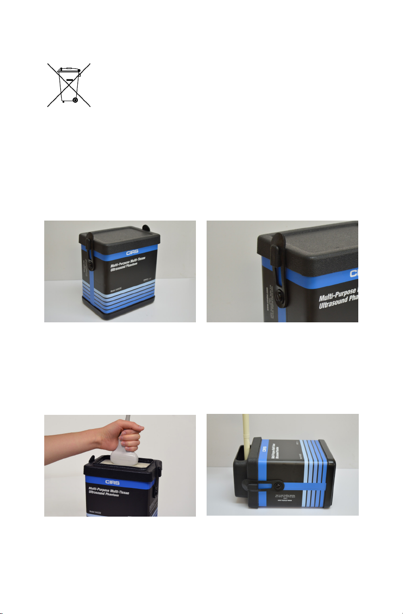
USE OF THE REMOVABLE WATER WELL AND COVERS
The phantom is shipped with the protective cover attached to the phantom. This
can be removed by stretching the elastic latches on either side of the phantom
up and off of the protective cover. The included water well and covers are easily
secured to the phantom with these same rubber latches. Simply place the water
well or cover on top of the phantom and stretch the elastic latches up and over the
attachment point on either side of the accessory.
Coupling gel can be applied directly to the scan surface. This option is best used
with linear transducers. For curved arrays, the water well may be attached and filled
with water to provide better coupling. Side Fire transducers can be particularly chal-
lenging to scan with a standard phantom. CIRS has designed a removable endo-
cavity cover for these transducers. When this accessory is attached, the phantom
should be placed on its back and the cover should be filled with water.
Cover on for storage Attach cover with latches
Water well for coupling curved probes Endocavity well
When finished scanning it is best to clean the scan surface of any water or coupling
gel and replace the protective cover.
HANDLING AND CARE (CONTINUED)

4
GENERAL GUIDELINES FOR PERFORMING MEASUREMENTS
It is recommended that all measurements be performed at the most frequently used
imaging arrangements. The importance of these tests is to make sure the system
performance remains constant over an extended period of time. Measurements
may also be used to compare the performance of various setups of the same ma-
chine or to compare different machines in a quantitative manner.
The following are general steps for imaging all targets:
• Some wires will appear as short lines rather than dots. When using the
electronic calipers, always take measurements from a point on one echo
to the same point on the next, i.e., center to center. Otherwise, errors may
be introduced.
• If a convex probe is used, center the target within the scan plane in order to
minimize degradation and distortion introduced on the outer edges of the
probe.
• When assessing vertical distance measurements, DO NOT press on the
scanning surface. Pressure on the scanning surface causes the wires
to become temporarily displaced, making vertical distance measure-
ments inaccurate.
• When assessing horizontal distance accuracy, ensure the scan plane is
perpendicular to the horizontal target group. Rotation of the probe will result
in inaccurate distances.
• Always be sure the phantom is scanned while at room temperature. A
phantom just received may be colder or hotter than room temperature de-
pending on where it was stored during shipping. Temperature affects the
speed of sound and, ultimately, the perceived measurements. The phantom
should be stored at room temperature for at least 24 hours before use to
ensure its core temperature is correct.
• The most accurate measurements will be made with the phantom 22˚C ±
1˚C (70˚F–73˚F).
ESTABLISHING A BASELINE
Before performing routine quality assurance measurements, establish:
1. System settings for each measurement:
System setup can have a dramatic impact on the results obtained from quality as-
surance measurements. You must establish and record what system settings
should be used for each of the quality assurance tests. These same settings
should be used each time the test is performed. If not, then the conclusions
drawn may not be valid. CIRS recommends that you use the most commonly
used settings for the type of probe tested- i.e. the liver preset values for an abdominal
probe- which are called a "normal" technique in the sections that follow.

5
2. Baseline measurements:
The first set of measurements taken will be the baseline measurements for the
combination of system settings and phantom. Record the system settings and
phantom serial number used to acquire each measurement along with
your measurement results. On subsequent scans, refer to the baseline results
to determine if the ultrasound system has drifted to an unacceptable level. It is
each facility's responsibility to establish the magnitude of drift allowed
before corrective action is warranted.
3. Allowable deviation from baseline measurements:
The difference between the original baseline measurements and subsequent
measurement should be calculated and recorded. At some point the difference
will be large enough that some action is required (call service, replace system,
etc.). Each facility needs to determine the action level for each test. You should
refer to the user’s manual of your ultrasound scanner and note the stated
accuracies of the system’s general imaging measurements. These stated ac-
curacies may greatly influence the conclusion made when evaluating the ultra-
sound system. For example, if the measurement accuracy for your system
is 10% for distances up to 2 cm, the scanner may detect 2.0 cm as being any
where from 1.8 cm to 2.2 cm and still be functioning properly. The user is
responsible for establishing action levels.
4. Frequency of system assessment:
How often each system is evaluated is also up to each facility to determine.
CIRS recommends at least annually.
Reference the accreditation programs established by the ACR and AIUM at
www.acr.org or www.aium.org for further guidance on establishing a QA program.
TESTING PROCEDURES
The following sections outline procedures for performing routine quality control tests
with the imaging targets contained within the 054GSE. It may be useful to refer to
the target map, shown in the Specifications section of page 13, when reviewing
these procedures.
UNIFORMITY TESTING
Uniformity is defined as the ability of the machine to display echoes of the same
magnitude and depth with equal brightness on the display. This is a good test to
ensure all crystals within the transducer are functioning.
1. Apply coupling gel to the scanning surface or fill the water trough with tap water.
2. Position the transducer on the scanning surface in a region with a minimum
number of targets.

6
UNIFORMITY TESTING (CONTINUED)
3. Adjust the instrument settings (gain, TGC, output, etc.) as for a “normal”
technique. Record these settings for use on subsequent testing.
4. Align the probe so that the targets are maximized.
5. Freeze the image and obtain a hard copy.
6. Observe the general appearance of the phantom. Note if all regions at the
same depth are displayed with the same intensity across the width of the image.
7. Record your observations.
DEPTH OF PENETRATION TESTING
Depth of penetration, also called maximum depth of visualization or sensitivity, is the
greatest distance in a phantom for which echo signals due to the scatterers within
the tissue-mimicking background material can be detected on the display. The
depth of penetration is determined by the frequency of the transducer, the attenua-
tion of the medium being imaged and the system settings.
1. Apply coupling gel to the scanning surface or fill the water trough with tap water.
2. Position the transducer to acquire an image of a vertical plane target. (The
wires should appear as dots, not lines).
3. Adjust the instrument settings (gain, TGC, output, etc.) as for a “normal”
technique. Record these settings for use on subsequent testing.
4. Align the probe so that all the vertical targets are displayed at their maximum
intensity level.
5. While actively scanning, look to see where the backscattered echoes within the
background material disappear. Be careful not to confuse electronic noise with
the background backscattered echoes. Electronic noise will move but back-
scattered echoes will remain stationary while maintaining the transducer in a
fixed position.
6. Freeze the image.
7. With electronic calipers measure the distance between the scanning surface
and the last identifiable echoes due to scattering. Note: Usually the wires stay
visible even though the backscattered echoes are not. Remember to measure
the distance to the scattered echoes, not to the last visible wire.
8. Record this distance on a record sheet and compare with baseline depth.
ATTENTION:
To register accurate vertical distance measurements, DO NOT APPLY
PRESSURE TO THE SCANNING SURFACE! CIRS strongly encourages the
user to scan the phantom with the water well filled with water or coupling gel
so the transducer does not make direct contact with the scanning surface. As
with a patient,
even the slightest amount of pressure on the scanning surface will
cause incorrect distances to be measured.

7
BEAM PROFILE, FOCAL ZONE AND LATERAL RESPONSE WIDTH
The beam profile is the shape of the ultrasound beam. A typical beam profile is
shown in Figure 1. The narrowest region within the beam profile is indicative of the
focal point. By convention, the region surrounding the focal point with intensity
within 3 dB of maximum is the focal zone. The best images are obtained while
within the focal zone. The vertical wire target group is useful for determining the
beam profile and the focal zone of a system, as follows:
1. Apply coupling gel to the scanning surface or fill the water trough with tap
water.
2. Position the transducer in a vertical plane. (The wires should appear as dots,
not lines).
3. Adjust the instrument settings (gain, TGC, out
put, etc.) as for a “normal” liver technique. Re-
cord these settings for use on subsequent test-
ing.
4. Align the probe so that all the vertical targets are
displayed at their maximum intensity level to
insure the transducer is imaging a vertical plane.
5. Freeze the image and obtain a hard copy.
6. Some of the targets will appear as short horizon
tal lines rather than dots on the frozen image.
7. Measure the horizontal length of the targets.
These measurements represent the lateral re-
sponse width of the system at the different
depths and setup. The minimum length is indica-
tive of the location of the focal point.
8. If a smooth curve is drawn to connect the edges of the targets, the beam profile
is easily discernible.
9. If using a variable focused transducer, repeat the above procedure for several
different focal zones (those settings most commonly used are recommended).
10. Record the focal point and save the hard copy.
VERTICAL DISTANCE MEASUREMENTS
A vertical distance is defined as the distance along the axis of the beam. The verti-
cal wire targets are used to assess the accuracy of vertical distance measurements
as follows:
1. Apply coupling gel to the scanning surface or fill the water trough with tap
water.
2. Position the transducer in a vertical plane. (The wires should appear as dots,
not lines). Do not apply excessive pressure as this may temporarily
compress the target and skew the measurements.
Figure 1 - Typical Beam Profile

8
VERTICAL DISTANCE MEASUREMENTS (CONTINUED)
3. Adjust the instrument settings (gain, TGC, output, etc.) as for a “normal”
technique. Record these settings for use on subsequent testing.
4. Align the probe so that all the vertical targets are displayed at their maximum
intensity level.
5. Freeze the image and obtain a hard copy.
6. Using electronic calipers measure the distances between two wires at various
depths or align the echoes to the display markers for comparison.
7. Record these measurements.
8. Compare the measured values with the recorded baseline distances.
HORIZONTAL DISTANCE MEASUREMENTS
The horizontal target group is used to determine the accuracy of measurements
made perpendicular to the beam axis. This group has 7 wires positioned 20 mm
apart at a depth of 9 cm (see target diagram attached to your phantom). Testing is
performed as follows:
1. Fill the water trough with tap water.
2. Position the transducer in a vertical plane. (The wires should appear as dots,
not lines).
3. Adjust the instrument settings (gain, TGC, output, etc.) as for a “normal”
technique. Record these settings for use on subsequent testing.
4. Align the probe so that all the horizontal targets are displayed at their maximum
intensity level.
5. Freeze the image and obtain a hard copy.
6. Using electronic calipers, measure the distances between two wires along the
horizontal plane.
7. Record these measurements.
8. Compare the measured values with the known distances between the targets.
AXIAL AND LATERAL RESOLUTION TESTING
Axial resolution is defined as the ability of an ultrasound system to resolve objects in
close proximity along the axis of the beam. In other words, it determines how close
can two objects be along the axis of the beam and still be detected as two distinct
objects. Axial resolution is proportional to the length of the system’s transmitted
ultrasonic pulse or pulse length.
Lateral resolution is similar to axial resolution except it is concerned with the resolu-
tion perpendicular to the beam axis. Lateral resolution will improve with a narrowing
of the beam width. Therefore, within the focal zone, the lateral resolution will be at
its best.

9
The Model 054GS has two combined axial and lateral resolution target groups. The
first group, at a depth of 3 cm, is designed for probes of 5 MHz and above. It con-
sists of 13 parallel nylon wires of 80 microns diameter. The second target is located
at 11 cm depth for evaluation of low frequency probes. It consists of 11 parallel
nylon wires of 80 microns diameter.
To measure axial and lateral resolution, refer to figures 2 and 3 for the layout of the
axial/lateral target groups and perform the following steps:
1. Apply coupling gel to the scanning surface or fill the water trough with tap
water.
2. Position the transducer above the axial resolution targets in a vertical plane.
(The wires should appear as dots, not lines).
3. Adjust the instrument settings (gain, TGC, output, etc.) as for a “normal”
technique. Record these settings for use on subsequent testing.
4. Align the probe so that all the targets are displayed at their maximum intensity
level.
5. Freeze the image and obtain a hard copy.
6. Examine the image to determine the last pair of wires to be distinguished as
two separate entities. If the last pair of wires to be resolved is separated by
a distance of 1 mm then record the axial resolution as being “in between
0.5 mm and 1.0 mm”.
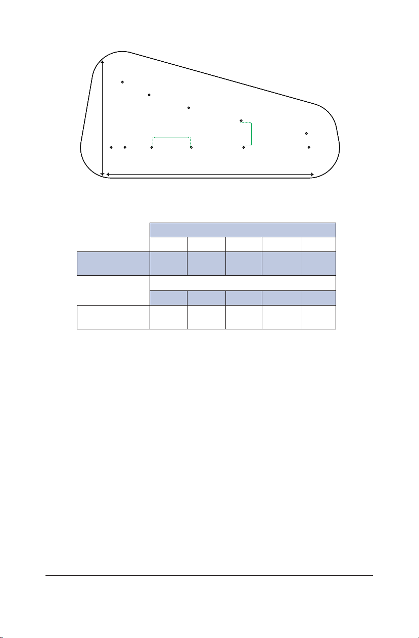
Targets
A1-B1 A2-B2 A3-B3 A4-B-4 A5-B5 A6-B6
Axial
Resolution (mm)
0.25 0.5 1.0 2.0 3.0 4.0
Targets
A1-A2 A2-A3 A3-A4 A4-A5 A5-A6 A6-A7
Lateral
Resolution (mm)
4.00 3.0 2.0 1.0 0.5 0.25
Axial Resolution
Lateral Resolution
A7 A6 A5 A4 A3
B6
B5
B4
B3
B2
A2
B1
A1
Edge to
adjacent Edge
2.00 mm Edge to
adjacent Edge
1.00 mm
Figure 2 - Combined Axial/Lateral Resolution Targets at 3 cm depth(top) and a table
listing distances between them (bottom)
10
ELEVATIONAL TESTING
A full characterization of system resolution requires a measurement of elevational
resolution, or slice thickness. Slice thickness is typically much coarser than axial
and lateral resolution as most ultrasound transducer arrays are mechanically fo-
cused in the thickness dimension.
Elevational resolution may be estimated using a method first described by Skol-
nick(1). It uses the vertical wire targets as follows:
1. Apply coupling gel to the scanning surface or fill the water trough with tap
water.
2. Adjust the instrument settings (gain, TGC, output, etc.) as for a “normal” tech-
nique. Record these settings for use on subsequent testing
3. Orient the transducer to image the length of the vertical target wires, taking
care to adjust the tilt so that the wires are lined up in a vertical column.
4. Rotate the transducer 45°.so that only a partial length of the wires is now vis-
ible.
D5
D4
D3
D2
D1
C1
C2C3C4C5C6
Axial Resolution
Lateral Resolution
Edge to
adjacent Edge
2 mm
Edge to
adjacent Edge
1 mm
Figure 3 - Combined Axial/Lateral Resolution Targets at 11 cm depth
(top) and a table listing the distances between them (bottom)
Targets
C1-D1 C2-D2 C3-D3 C4-D4 C5-D5
Axial
Resolution (mm)
1.0 2.0 3.0 4.0 5.0
Targets
C1-C2 C2-C3 C3-C4 C4-C5 C5-C6
Lateral
Resolution (mm)
5.0 4.0 3.0 2.0 1.0
1.Skolnick, ML. “Estimation of ultrasound beam width in the elevation (section thickness) plane.” Radiology. 1991
Jul;180(1):286-8.

11
5. Freeze the image and measure the length of each wire segment with the elec-
tronic calibers.
6. Record the measurements.
LOW-CONTRAST TARGET DETECTABILITY
Machines have a tendency to represent low-contrast structures smaller than they
actually are and with irregular rather than smooth borders, this is referred to as fill-in.
It is desirous for these effects to be minimal.
In the Model 054GS, five cylinders having no scatter are provided in the phantom to
test a machine's ability to image cyst-like structures over range of depths. The cyl-
inders are 8 mm in diameter and located at depths of 4, 7, 10, 13, and 16 cm. Re-
fer to the target diagram attached to your phantom. The accuracy of the machine's
representation of the mass (proper size and shape) may be determined using this
target. Because of the low attenuation in this mass, you may notice enhancement
behind the target.
Testing for low-contrast target detectability is performed as follows:
1. Apply coupling gel to the scanning surface or fill the water trough with tap
water.
2. Position the transducer above the cyst of interest and perpendicular to the
wires. You should be imaging the circular cross section of the cylinders.
3. Adjust the instrument settings (gain, TGC, output, etc.) as for a “normal”
technique. Record these settings for use on subsequent testing.
4. Align the probe so that the target is maximized.
5. Freeze the image and obtain a hard copy.
6. Observe the general appearance of the tumor. Note if you are able to see the
mass
7. A more detailed analysis can be performed by measuring the width and height
of each mass.
8. Record your observations.
GRAYSCALE CONTRAST SENSITIVITY
In the Model 054GS, six cylinders having contrast ranging from anechoic to hy-
perechoic with respect to the background material are provided in the phantom
to test a machine's dynamic range. The cylinder diameter is 8 mm at a depth of 4
cm. These masses are useful in determining the ultrasonic system's capability of
distinguishing targets of varying gray scale levels. The accuracy of the machine's
representation of the mass (proper size and shape) may also be determined using
this target. Refer to target diagram attached to your phantom.

12
GRAYSCALE CONTRAST SENSITIVITY (CONTINUED)
1. Apply coupling gel to the scanning surface or fill the water trough with tap
water.
2. Position the transducer above the tumor and perpendicular to the wires.
(The tumor should appear as a circular region).
3. Adjust the instrument settings (gain, TGC, output, etc.) as for a “normal”
technique. Record these settings for use on subsequent testing.
4. Align the probe so that the target is maximized.
5. Freeze the image and obtain a hard copy.
6. Observe the general appearance of each tumor. Note if you are able to see
each of the masses.
7. A more detailed analysis can be performed by measuring the width and height
of the mass.
8. Record your observations.
DEAD ZONE ASSESSMENT
The near field group is used to assess the distance from the front face of the
transducer to the closest identifiable echo. This region, where no useful information
is obtained, is commonly referred to as the “dead-zone”, “ring-down distance”, or
"near field resolution." The dead zone occurs because the ultrasound system can-
not send and receive data simultaneously. It is instrument dependent and is dimin-
ished as frequency is increased. A change in your system’s dead zone is indicative
of a problem with the transducer, the pulsing system or both.
The near field group consists of parallel, 100 micron diameter, nylon, monofilament
wires horizontally spaced 6 mm apart from center to center (Figure 4). Vertical dis-
tance from the center of each wire to the top edge of the scanning surface ranges
from 6 mm down to 1 mm in 1 mm increments.
6mm
1mm
2mm
3mm
4mm
5mm
6mm 6mm 6mm
SCANNING
Wire Diameter 0.1mm Positional Accuracy ±0.2mm
6mm
6mm
Figure 4 - Near Field Target Spacing
The depth of the dead zone may be measured as follows:
1. Apply coupling gel to the scanning surface or fill the water trough with tap water.
2. Position the transducer above the near field resolution target and perpendicular
to the wires. (The wires should appear as dots, not lines).
13
3. Adjust the instrument settings (gain, TGC, output, etc.) to maximize
resolution in the near field. Record these settings for use on subsequent
testing.
4. Freeze the image while the near field targets are clearly displayed.
5. Count how many wires of the near field target you can see. Subtracting this
number from the total number of targets gives you the dead zone measurement.
For instance, if 3 targets are visible, the dead zone distance = 3 mm (6mm-
3mm).
An alternative method uses the electronic calipers to measure the distance
between the transducer face and the closest wire target to be resolved
from the everberation. If the first target to be resolved is at 4 mm, then the
dead zone distance is “something less than 4 mm”.
6. Record this distance and compare with baseline measurements.
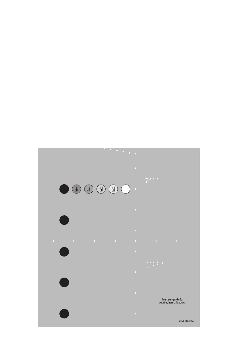
SPECIFICATIONS
TARGET LAYOUT
Hyperechoic
Near
Field
Axial-Lateral
Resolution
Gray Scale
Anechoic
Horizontal Distance
Axial-Lateral
Resolution
Vertical Distance
Anechoic Cylinders

14
WIRE TARGETS
Material Nylon monofilament
NEAR FIELD GROUP
Number of targets 6
Diameter 100 microns
Depth range 1 to 6 mm
Vertical distance between targets 1 mm
VERTICAL DISTANCE GROUP
Number of targets 8
Diameter 100 microns
Depth range 2 to 16 cm
Vertical distance between targets 20 mm
HORIZONTAL DISTANCE GROUP
Number of groups 1
Diameter 100 microns
Depths 9 cm
Number of targets 7
Horizontal distance between targets 20 mm
AXIAL / LATERAL RESOLUTION GROUPS
Group 1
Diameter 80 microns
Depths 3 cm
Axial & Lateral separation between targets 4, 3, 2, 1, 0.5 & 0.25 mm
Group 2
Diameter 80 microns
Depths 11 cm
Axial & Lateral separation between targets 5, 4, 3, 2, & 1 mm
ANECHOIC CYLINDERS
Number of Cylinders 5
Contrast Anechoic
Diameter 8 mm
Depths 4, 7, 10, 13 & 16 cm
PHANTOM
Housing ABS Plastic
Outer Dimensions 17.8 x 12.7 x 20.3 cm (7 x 5 x 8")
Scanning surface 14 x 9 cm Saran-based laminate
Scanning Material Zerdine®tissue mimicking gel
Speed of Sound 1540 m/s
Other Compatible with harmonic imaging

15
GRAY SCALE TARGETS
Number of Targets 6
Contrasts Anechoic, -6 dB, -3 dB, +3 dB,
+6 dB, & Hyperechoic
Diameter 8 mm
Depth 4 cm
ACCESSORIES
Removable water well, Removable endocavity cover, Removable storage cover,
Carry Case, Certificate of Compliance, User Guide and QA worksheet
NOTES
All dimensions without tolerances are nominal
All measurements made at 22˚C ± 1˚C
ZERDINE®
The Model 054GS is constructed from a patented, solid elastic material developed
at CIRS called Zerdine. Phantoms constructed from Zerdine will not melt or leak
when punctured and they do not require refrigeration. Zerdine is also more elastic
than other materials and allows more pressure to be applied to the scanning sur-
face without subsequent damage to the material. At normal room temperatures,
Zerdine will accurately simulate the ultrasound characteristics found in human liver
tissue. Specific proprietary fabrication procedures enable close control over the
homogeneity of Zerdine and the reliability of its acoustic characteristics from batch
to batch.
The formulation system established at CIRS is geared to independently control:
• The speed of sound in the optimal range of 1510 to 1700 m/s.
• Attenuation in the optimal range of 0.05 and 1.5 dB/cm-MHz.
• Scatter or relative contrast in the optimal range of -15 to +15 dB in
relation to a scatter baseline equivalent to human liver tissue.
• Elasticity with a Young Modulus in the optimal range of 4 to 90 kPa.
At normal room temperature, Zerdine response to ultrasonic excitations will simulate
the ultrasonic response of human tissue. The relation between the acoustic attenu-
ation, A, and the acoustic frequency, F, is of the form A = AoFnwith values of the
power coefficient, n, in the range of 0.8 to 1.10, indicating the proportional increase
of the acoustic attenuation with frequency. Backscatter characteristics can be ad-
justed through the addition of predetermined amounts of calibrated scatter material,
and are fully compatible with harmonic imaging. Zerdine can be molded into very
intricate shapes, and the material can be cured in layers allowing the production of
“multi-tissue” phantoms. Zerdine, like most other phantom materials, will desiccate
if unprotected; thus, all phantoms must be stored properly. If stored in the case
provided, your phantom should last many years.

16
WARRANTY
All standard CIRS products and accessories are warranted by CIRS against defects
in material and workmanship for a period as specified below. During the warranty
period, the manufacturer will repair or, at its option, replace, at no charge, a product
containing such defect provided it is returned, transportation prepaid, to the manu-
facturer. Products repaired in warranty will be returned transportation prepaid.
There are no warranties, expressed or implied, including without limitation any im-
plied warranty of merchantability or fitness, which extend beyond the description on
the face hereof. This expressed warranty excludes coverage of, and does not pro-
vide relief for, incidental or consequential damages of any kind or nature, including
but not limited to loss of use, loss of sales or inconvenience. The exclusive remedy
of the purchaser is limited to repair, recalibration, or replacement of the product at
manufacturer’s option.
This warranty does not apply if the product, as determined by the manufacturer,
is defective because of normal wear, accident, misuse, or modification.
Non-Warranty Service
If repairs or replacement not covered by this warranty are required, a repair estimate
will be submitted for approval before proceeding with said repair or replacement.
Returns
If you are not satisfied with your purchase for any reason, please contact your local
distributor prior to returning the product. Visit https://www.cirsinc.com/distributors/
to find your local distributor. If you purchased your product direct through CIRS, call
Customer Service at 800-617-1177, email [email protected], or fax an RMA request
form to 757-857-0523. CIRS staff will attempt to remedy the issue via phone or
email as soon as possible. If unable to correct the problem, a return material
authorization (RMA) number will be issued. Non-standard or “customized” products
may not be returned for refund or exchange unless such product is deemed by
CIRS not to comply with documented order specifications. You must return the
product to CIRS within 30 calendar days of the issuance of the RMA. All returns
should be packed in the original cases and or packaging and must include any
accessories, manuals and documentation that shipped with the product. The RMA
number must be clearly indicated on the outside of each returned package. CIRS
recommends that you use a carrier that offers shipment tracking for all returns and
insure the full value of your package so that you are completely protected if the
shipment is lost or damaged in transit. If you choose not to use a carrier that offers
tracking or insure the product, you will be responsible for any loss or damage to the
product during shipping. CIRS will not be responsible for lost or damaged return
shipments. Return freight and insurance is to be pre-paid.
With RMA number, items may be returned to:
CIRS
Receiving
900 Asbury Ave,
Norfolk, Virginia, 23513 USA
Product Warranty Period
Model 054GS - General Purpose Ultrasound Phantom 48 Months

17
APPENDIX 1: QUALITY ASSURANCE RECORD FOR MODEL 054GS
MODEL 054GS
GENERAL PURPOSE ULTRASOUND PHANTOM
QUALITY ASSURANCE RECORD
Location: ___________________ Unit: _________________Probe: _______________ QC Phantom SN: _______________
Machine Settings:
Depth of Field (FOV) ________________________ cm Gain: _______________________ Power: _________________
Focal Zone(s) ______________ cm ____________ cm _____________cm __________ cm _________cm
Preprocessing__________________ Post Processing _____________________________ Dynamic Range _____________
Other: ________________________________________________________________________________________________
TEST
BASELINE
REMARKS
TEST RESULTS
VARIANCE
COMMENTS
Uniformity
Near Field
Vertical Distance
Depth of
Penetration
Focal Zone
Horizontal
Distance
Axial / Lateral
Resolution
3 cm
11 cm
Anechoic Cylinder
Gray Scale
Duplicate as Needed:
CIRS, Inc., 2428 Almeda Avenue, Suite 316, Norfolk, VA 23513
(800) 617-1177 * (757) 855-2765 or Fax (757) 857-0523
One Sheet Per System Setup
TEST BASELINE
REMARKS
TEST
RESULTS VARIANCE COMMENTS
Uniformity
Depth of
Penetration
Beam Prole/
Focal Zone/
Lateral Width
Response
Vertical Distance
Horizontal
Distance
Axial and Lateral
Resolution
3 cm
11 cm
Elevational
Resolution
Low-Contrast
Target
Detectability
Gray Scale
Contrast
Sensitivity
Near Field
Duplicate as Needed
One Sheet Per System Setup

©
2013 Computerized Imaging Reference Systems, Inc. All rights reserved.
Specifications subject to change without notice.
Publication: 054GS UG 062119
Computerized Imaging Reference Systems, Inc. has been
certified by UL DQS Inc. to (ISO) 13485:2016. Certificate
Registration No.10000905-MP2016.
COMPUTERIZED IMAGING
REFERENCE SYSTEMS, INC.
900 Asbury Ave
Norfolk, Virginia 23513 • USA
TOLL FREE 800.617.1177
TEL: 757.855.2765
FAX: 757.857.0523
EMAIL: [email protected]
www.cirsinc.com
Technical Assistance
1.800.617.1177
Table of contents
Other Cirs Industrial Equipment manuals


