VKS
3
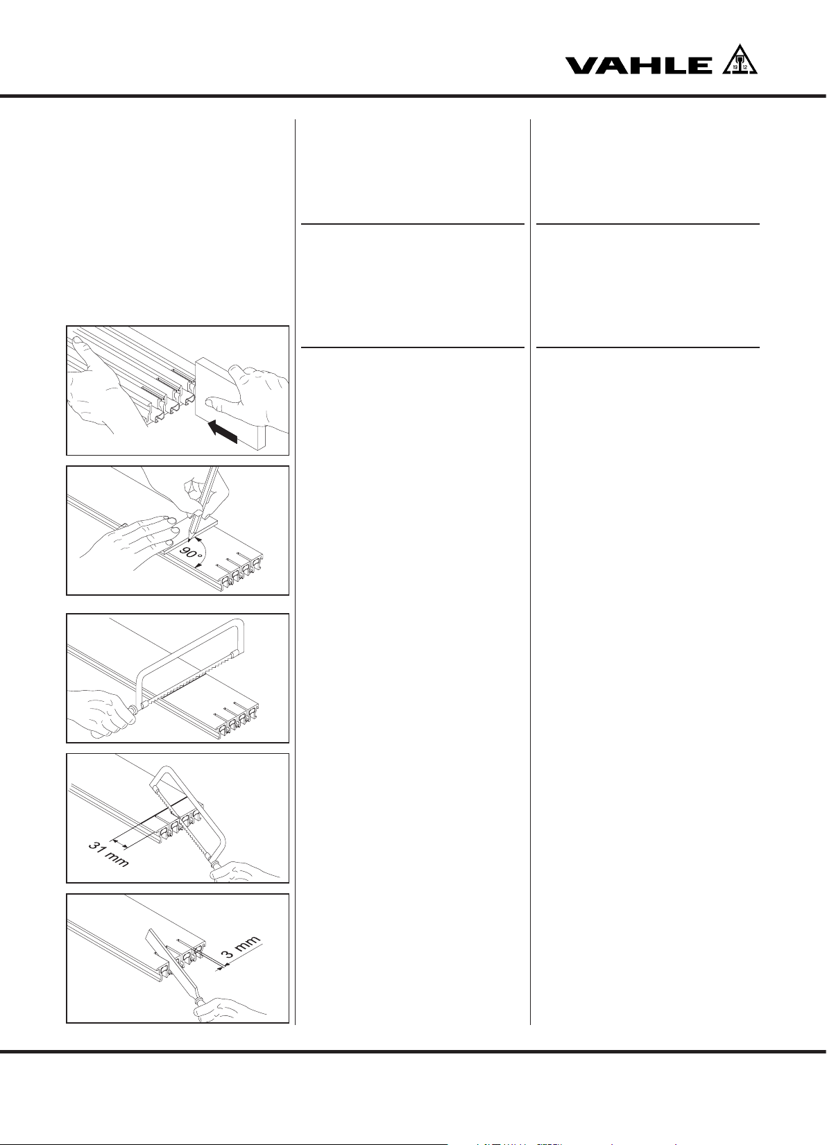
Mounting instructions •Instrukcja monta˝u
Safety Instructions
Warnings and Symbols
The following denominations and sym-
bols are used in this manual for particu-
larly important indications:
BRisk of injury by electric
shock!
Here, you are warned of situa-
tions which may bring about
the risk of electric shock.
SRisk of damage!
Here, you are warned about
situations which may result in
damage to the conductor rails
or other parts of the assembly.
These situations may result in danger to
persons, but also in damage to equip-
ment (e. g. damage to the conductor rail).
HThe hand symbol with the
stretched index finger indi-
cates text passages which
provide you with additional in-
dications and tips.
Read all safety instructions in this manual
carefully and observe them during the
work.
BBefore starting the installa-
tion work, it is mandatory
that you disconnect the plant
from the mains!
Observe the regulations
which apply to your country
during the installation work.
SRisk of pinching!
You must ensure that the
arrangement of the conductor
system provides minimum dis-
tances (0.5 m) between fixed
and mobile plant parts (i.e. be-
tween conductor rail, collector
trolleys and towing arms) so as
to avoid the risk of pinching!
Personnel qualifications
Only such personnel may do installation
work who are qualified as follows:
Instrukcje bezpieczeƒstwa
Wskazówki ostrzegawcze i symbole
W celu wyró˝nienia szczególnie wa˝nych
informacji w niniejszej instrukcji zasto-
sowano nast´pujàce nazewnictwo i oz-
naczenia:
BNiebezpieczeƒstwo obra˝eƒ
na skutek pora˝enia pràdem!
Sygnalizowane sà tutaj sy-
tuacje, w których istnieje
niebezpieczeƒstwo pora˝enia
pràdem elektrycznym.
SNiebezpieczeƒstwo
uszkodzenia!
Sà tutaj sygnalizowane sy-
tuacje, w których mogà zostaç
uszkodzone lub zniszczone
szyny pràdowe lub inne ele-
menty zabudowy.
Sytuacje takie mogà wiàzaç si´ z zagro-
˝eniem dla osób, ale tak˝e z zagro˝eniem
dla wyposa˝enia (np. z uszkodzeniem
szyn pràdowych).
HD∏oƒ z wyciàgni´tym palcem
wskazuje miejsca, w których
mo˝na znaleêç uzupe∏niajàce
wskazówki i porady.
Starannie przeczytaj wszystkie instruk-
cje bezpieczeƒstwa w tej instrukcji mon-
ta˝u i przestrzegaj ich podczas pracy.
BPrzed rozpocz´ciem prac
monta˝owych bezwzgl´dnie
od∏àczyç napi´cie od insta-
lacji!
Podczas wszystkich prac
monta˝owych przestrzegaç
specyficznych przepisów
krajowych.
SNiebezpieczeƒstwo
zmia˝d˝enia!
Nale˝y zagwarantowaç przez
rozmieszczenie szyn pràdo-
wych, szynoprzewodów, odbie-
raków pràdu i ramion zabiera-
ków odst´py bezpieczeƒstwa
nie mniejsze ni˝ 0,5 m mi´dzy
nieruchomymi a ruchomymi
elementami instalacji, by zapo-
biec zagro˝eniu zmia˝d˝eniem!
Kwalifikacje personelu
Monta˝ mo˝na zlecaç tylko odpowiednio
wykwalifikowanemu personelowi, a wi´c
osobom: