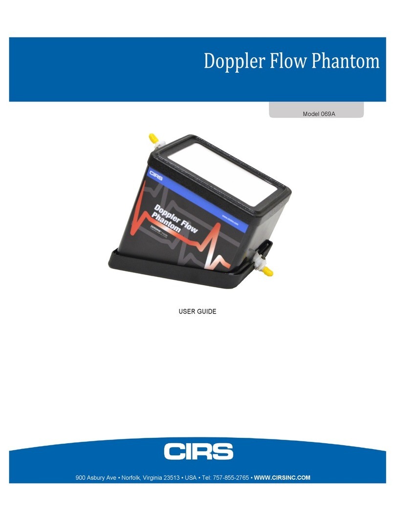
Cirs ATS 527 User manual

ATS Laboratories
A CIRS Company
900 Asbury Ave
Norfolk, VA 23513
Model 527
Directional Discrimination Doppler Flow Phantom
Revised February 2015
Made in USA

INTRODUCTION
The Doppler Flow phantoms provide a reliable means of evaluating a Doppler Flow Imaging
System's ability to detect the location and direction of flow, flow velocity and sensitivity.
The phantoms are constructed of a rubber-based tissue mimicking material. This material extends
the useful life of the phantom by avoiding problems due to melting, freezing, dehydration and
breakage from dropping, which are commonly associated with hydrogel (water-based) phantoms.
By eliminating these problems, the durability, quality and reliability of this product is guaranteed for
three years.
The acoustic properties of all biologic and non-biologic materials are affected by temperature
variations. Most diagnostic imaging systems and tissue-mimicking phantoms are calibrated at
room temperature, commonly referred to as 23°C. To ensure measurement accuracy ATS
incorporates a thermometer strip affixed to the outside surface of the phantom.
The sound velocity of most diagnostic imaging systems is calibrated to 1,540 meters per second
(mps), the assumed average velocity of sound through human soft tissue. The rubber-based
tissue-mimicking material has a sound velocity of 1450 mps with an attenuation coefficient of
0.5dB/cm/Mhz when measured using a 3.5 MHz transducer at room temperature (23°C).
The differences in the speed of sound if gone uncorrected, will cause distortion of the distance
(e.g. depth of penetration) measurements obtained. The measurements are corrected by
multiplying the measurements obtained by the correction factor of 0.94.
The rate of fluid flow through the phantom when measured by a Doppler imaging system is not
affected by the differences in sound velocity, therefore, distortion of these measurements will not
occur.
PRODUCT DESCRIPTION
The Model 527 tissue mimicking Doppler flow phantom is designed to test directional
discrimination of color Doppler flow imaging systems. This phantom monitors the ability of the
system to discriminate the direction of flow in small vessels, of close proximity, at varying depths.
The phantom contains four pairs of 2.0 mm flow channels. Connecting the channels (as shown in
Figure 2) creates bi-directional flow within the pair at equal flow rates. The edge-to-edge spacing
between the flow channels within the each pair progressively increases from 1.0 mm to 4.0 mm.
A fixed-angled scan surface maintains a constant angle between the sound beam and the test
fluid flowing through the phantom at 18° or 56° permitting continuous scanning at depths ranging
from 3.0 to 17.0 cm.
!2

TEST PERFORMED
•Directional Discrimination
•Flow Velocity
•Sensitivity at varying depths
•Maximum Penetration
•Location of Flow
SPECIFICATIONS
GENERAL
Overall Dimensions: 32.0 x 13.5 x 16.0cm*
Weight: 15.2 lbs - 6.9 Kg*
Housing Material: PVC
Wall Thickness: 1.0 cm*
Scan Surfaces: 2
Dimensions: 25.5 x 11.5cm @ 18°
9.5 x 11.5cm @ 56°
TISSUE MIMICKING MATERIAL
Type: Urethane rubber
Freezing Point: < -40°C
Melting Point: > 100°C
Attenuation Coefficient: 0.5 dB/cm/MHz measured at 3.5 MHz
Speed of Sound: 1450 m/s at 23°C
FLOW CHANNELS:
Type: Circular
Number of Channels: 8
Number of Pairs: 4
Diameters: 2.0 mm
Scan Surface Depths: 3.0 - 11.0 cm @ 18°
3.5 - 15.0 cm @ 56°
Maximum Fluid
Pressure: 8 psi
CONNECTORS:
Type: Luer-Lock
*Nominal dimensions
!3

Figure 1
SET-UP PROCEDURE
NOTE: THE SET-UP OF THE MODEL 527 IS UNIQUE PLEASE FOLLOW THE DIRECTIONS
GIVEN BELOW CAREFULLY.
The Model 527 is designed to be used in conjunction with ATS Model 707 Doppler Test Fluid and
the ATS Model 700 ATS Doppler Flow Controller and Pumping System.
Equipment and Materials Required
The Model 527 is supplied with various parts, please check to make sure you have
received the following items:
Procedure
1. Check to make sure the above equipment/materials are available.
2. Select a clean, flat, stable working surface. Arrange the system components to provide easy
access during a testing procedure. The phantom should be positioned near the pumping system.
3. Set-up the Doppler Flow Pumping System according to the manufacturers directions. Follow the
steps below when connecting the Model 527.
16
Male Luer-lock Plugs
1
4" (Inside Diameter 3/32") Connecting Tubing with Male Luer-Lock
connectors on both ends. Used to connect matching channel pairs at
one end of the phantom.
1
6" (Inside Diameter 3/32") Connecting Tubing with Male Luer-Lock
connectors on both ends. Used to connect unmatched pairs at one end
of the phantom, requiring a long distance.
!4

4. Connect the Model 527 phantom to the pumping system as shown on the above diagram.
5. All of the flow channels need to be filled with test fluid to avoid an air-phantom interface.
6. When you are now ready to prime the pumping system and fill the flow channels, turn the
"Speed Dial" on the pump driver to "0". Turn on the pump. Slowly increase the speed of the pump
to achieve the desired fluid flow. Allow the pump to run until it is completely primed and no visible
air-bubbles are seen in the tubing. When is accomplished, turn the "Speed Dial" back to "0".
7. Disconnect the pair #1 flow channel and replace the luer-lock plugs, to prevent the fluid from
leaking out of the channels.
8. Repeat this procedure for the remaining flow channel pairs.
NOTE: In the operation of any flow phantom it is likely some air bubbles will enter the fluid stream;
either through cavitation in areas of expanded diameters or entrainment of air at a fitting or
connector. For these reasons a large reservoir is required. As the pump begins to circulate the test
fluid through the system, entrapped air bubbles will enter the fluid and be pumped into the return
side of the reservoir.
9. Select the desired flow channel pairs for testing. Use the procedure above to connect the flow
channels to the pumping system. If greater edge-to-edge distances are required, a combination of
two flow channel pairs can be used as illustrated in Figure 2.
NOTE: THE PRESSURE OF THE FLUID DELIVERED TO THE PHANTOM MUST NOT EXCEED
8 psi (POUNDS PER SQUARE INCH). IF FLUID PRESSURES ARE USED IN EXCESS OF 8 psi
THE PHANTOM WILL BE PERMANENTLY DAMAGED.
The phantom is now ready for performance testing.
!5

!6

CARE AND HANDLING OF QUALITY ASSURANCE RUBBER-BASED PHANTOMS
For best results the phantom should be kept clean at all times. In particular a build-up of dried coupling gel
on the scan surface should be avoided. The phantom may be cleaned with warm water using a lint free
cloth. Particularly stubborn stains and dirt may be removed with a mild household cleaner. The use of
petroleum solvents should be avoided since they may adversely react with the rubber-based material.
When doppler flow testing has been completed, pump an adequate amount of water through the channels
to remove the test fluid prior to storing.
NOTE: THE PRESSURE OF THE FLUID DELIVERED TO THE PHANTOM MUST NOT EXCEED 8 psi
(POUNDS PER SQUARE INCH). IF FLUID PRESSURES ARE USED IN EXCESS OF 8 psi THE
PHANTOM WILL BE PERMANENTLY DAMAGED.
STATEMENT OF WARRANTY
ATS Laboratories, Incorporated warrants that for the duration of the warranty period, its products are free
from functional defects in materials and workmanship. If ATS Laboratories, Incorporated, deems the
product to be defective, at our sole option, we will repair or replace the product, free of charge in a
reasonable amount of time.
Warranty Period:
The warranty period begins on the date the product is delivered to the purchaser.
Rubber-Based Phantoms Lifetime defined as between 10 years
Conditions of Warranty
1. The defect must be reported and the Product returned to ATS Laboratories, Incorporated within
the warranty period.
2. The Product must be packaged properly to avoid damage during shipping.
3. All transportation charges will be paid by the purchaser.
Invalidation of Warranty
1. If the product has been altered or repaired other than by ATS Laboratories, Incorporated.
2. If the product has been subject to abuse, misuse, negligence or accident such as;
Rubber-Based Doppler Flow Phantoms:
a. If the purchaser has exposed the Phantom to petroleum solvents.
b. If the phantom has been subjected to fluid pressure above 8 psi (pounds per
square inch).
ATS shall not be otherwise liable for any damages, including but not limited to incidental damages,
consequential damages, or special damages.
There are no express or implied warranties which extend beyond the warranties as stated above.
!7

Table of contents
Other Cirs Test Equipment manuals
