Cojali Jaltest SST User manual

English 3
Index
Contenido
Index 3
General Information 4
1.1 PRODUCT DESCRIPTION 4
1.2 GENERAL RULES FOR USE 4
1.3 EQUIPMENT COMPOSITION 5
1.4 FUNCTIONS AND CONNECTIONS 6
Procedures 7
2.1 READ MODE 7
2.2 SIMULATION MODE 8
Connection diagrams 11
Technical data 14
index nextprevious
Access the
content you
need quickly by
clicking on
Easy navigation

English 4
General Information1
1.1 PRODUCT DESCRIPTION
1.2 GENERAL RULES FOR USE
Jaltest SST is a small portable equipment designed to check the correct operation
of active and passive speed sensors, as well as to simulate both sensors to detect
possible errors in the ECUs to which they are connected.
Jaltest SST has a button that allows the user to interact with the device to select the
operating mode. The user, through a lighting panel of LED devices, can easily detect
possible errors without the need to carry out difcult and complex tests.
This product enables the user to signicantly reduce the time spent on checks and
fault detection since it allows for the detection of the focus of the issue.
ٚRead the instructions carefully before using the device for the rst time.
ٚPrevent non-qualied personnel from using the equipment.
ٚPrevent the equipment from getting wet with water or other liquids.
ٚStore the equipment and its components inside their box and in a dry place,
away from heating sources and out of reach of sunlight.
ٚPrevent the equipment from being knocked and falling out.
ٚTurn off the equipment after being used to save battery life.

English 5
1.3 EQUIPMENT COMPOSITION
Jaltest SST is made up of an
electronic device with an
operating interface with a button
and LEDs, as well as a complete
kit of cables and multipins that
allow connection in the sensor
and ECU connector pins. It has
a 9 V alkaline battery type 6LR61.
1. On/Off & mode change button
This mode allows the user to
interact with the device (see
details in the Function table on
page 6). There are 3press types:
• Short press (less than 1s): It changes mode when no mode is selected. If a mode is
selected, it carries out a specic action of the mode (see Function table on page 6).
• Long press (between 1s and 3s): It selects the desired mode. If a mode is already selected,
it returns to start mode.
• Extra-long press (more than 3 s): It turns off the device.
2. Error detection
A red LED lights up if an open circuit, short circuit, or power supply problem is
detected.
3. Sensor type
A green LED indicates whether an active or passive sensor is being read or simulated.
4. Low Battery
A red LED lights up if the battery is too low.
5. Simulation LEDs and signal status
In simulation/read mode, 4 green LEDs ash sequentially clockwise, indicating that
the signal is being simulated/read.
6. Connections
3banana female connectors. The connection positions; power supply (red), signal
(blue), and ground (black) are indicated in the upper part of the control panel.

English 6
1.4 FUNCTIONS AND CONNECTIONS
During the navigation trough different modes, the user will be able to detect the mode
to be selected through lighting of LEDs involved, which will ash simultaneously. In
addition, in this mode, LEDs of the possible errors to be detected will light up.
Connections:
Warning: To prevent possible errors, ensure that you have selected the correct mode
for the desired connection.
To connect Jaltest SST device to sensor or ECU, the multipin kit should be used as
follows:
Function table:
* Depending on the vehicle mode, it may be necessary to connect the device ground to the vehicle chassis (see
IMAGE 5 in the connection diagram section).
Note: An incorrect connection cannot damage the device, since it is protected against polarity inversion.
Jaltest SSTJaltest SST
connectorconnector Function Connect to ACTIVE sensor Connect to PASSIVE sensor
Simulation Read Simulation Read
Red Sensor power
supply (+) YES YES YES YES
Black Ground (-) YES YES NO* NO
Blue SIGNAL YES YES YES YES
DEVICE STATUS SHORT PRESS LONG PRESS EXTRA-LONG PRESS
OFF START MODE - -
START MODE
CHANGE TO
«ACTIVE SENSOR READ
SELECTION» MODE
-IT TURNS OFF THE DEVICE
«ACTIVE SENSOR READ
SELECTION» MODE
CHANGE TO
«PASSIVE SENSOR READ
SELECTION» MODE
CHANGE TOCHANGE TO
«ACTIVE SENSOR READ»«ACTIVE SENSOR READ»
MODEMODE
IT TURNS OFF THE DEVICE
«PASSIVE SENSOR READ
SELECTION» MODE
CHANGE TO «ACTIVE SENSOR
SIMULATION SELECTION»
MODE
CHANGE TOCHANGE TO
«PASSIVE SENSOR READ»«PASSIVE SENSOR READ»
MODEMODE
IT TURNS OFF THE DEVICE
«ACTIVE SENSOR
SIMULATION SELECTION»
MODE
CHANGE TO «PASSIVE
SENSOR SIMULATION
SELECTION» MODE
CHANGE TOCHANGE TO
«ACTIVE SENSOR«ACTIVE SENSOR
SIMULATION» MODESIMULATION» MODE
IT TURNS OFF THE DEVICE
«PASSIVE SENSOR
SIMULATION SELECTION»
MODE
CHANGE TO
«ACTIVE SENSOR READ
SELECTION» MODE
CHANGE TOCHANGE TO
«PASSIVE SENSOR«PASSIVE SENSOR
SIMULATION» MODESIMULATION» MODE
IT TURNS OFF THE DEVICE
«ACTIVE SENSOR READ»
MODE
IT RESETS
PRESENT ERRORS
CHANGE TO
«START» MODE IT TURNS OFF THE DEVICE
«PASSIVE SENSOR READ»
MODE
IT RESETS
PRESENT ERRORS
CHANGE TO
«START» MODE IT TURNS OFF THE DEVICE
«ACTIVE SENSOR
SIMULATION» MODE
IT CHANGES SIGNAL
FREQUENCY AND RESETS
PRESENT ERRORS
CHANGE TO
«START» MODE IT TURNS OFF THE DEVICE
«PASSIVE SENSOR
SIMULATION» MODE
IT CHANGES SIGNAL
FREQUENCY AND RESETS
PRESENT ERRORS
CHANGE TO
«START» MODE IT TURNS OFF THE DEVICE

English 7
2.1 READ MODE
· ACTIVE speed sensor:
In this mode, the speed sensor is disconnected from the ECU and connected to
the Jaltest SST device to be able to check it in isolation. By turning the component
whose sensor the user wants to check, they can determine if the sensor generates
a correct signal.
1 Disconnect the speed sensor from the vehicle and connect it to the Jaltest SST
device through multipins according to the IMAGE 1 of the connection diagram
section.
2Turn on the device and go into Active Sensor Read mode interacting with the
selection button of the mode (1) according to the presses described in the function
table on page 6. The Active Sensor LED must be on, as well as the LED of the errors
that may appear.
3Turn the component whose sensor you want to check.
4 Signal check: When the component is turning at constant speed, the status LEDs
of the signal must ash sequentially, clockwise, and consistently.
5Error check:
ٚThe status LEDs of the signal ash inconsistently: The sensor does not detect a
consistent turn signal.
ٚThe short circuit error LED lights up: Short circuit to power supply has occurred
during the execution of the test.
ٚThe power supply error LED lights up: Incorrect mode has been selected
(simulation).
Note: It is possible to repeat the test with just a short press of the selection button of the mode (1). The
device performs an error reset and starts the test again.
2 Procedures

English 8
· PASSIVE speed sensor:
In this mode, the speed sensor is disconnected from the ECU and connected to the
Jaltest SST device to be able to check it in isolation. By turning the component whose
sensor the user wants to check, they can determine if the sensor generates a correct
signal. For example, by manually turning a vehicle wheel with speed sensor.
1Disconnect the speed sensor from the vehicle and connect it to the Jaltest SST
device through multipins according to the IMAGE 2 of the connection diagram
section.
2Turn on the device and go into Passive Sensor Read mode interacting with the
selection button of the mode (1) according to the presses described in the function
table on page 6. The Passive Sensor LED must be on, as well as the LED of the errors
that may appear.
3Turn the component whose sensor you want to check.
4 Signal check: When the wheel is turning at xed speed, the status LEDs of the
signal must ash sequentially and constantly.
5Error check:
ٚThe status LED of the signal ash inconsistently: the sensor does not detect a
consistent turn signal.
ٚThe open circuit error LED lights up: Wiring or sensor is defective.
ٚThe short circuit error LED lights up: Short circuit to ground (chassis) or power
supply has occurred during the execution of the test.
ٚThe power supply error LED lights up: Incorrect mode has been selected
(simulation).
Note: It is possible to repeat the test with just a short press of the selection button of the Mode. The
device performs an error reset and starts the test again.
2.2 SIMULATION MODE
Important! Jaltest SST cannot operate as a substitute for the vehicle speed sensor
so, in some cases, it is normal that the ECU has present errors concerning the
disconnected component.
ACTIVE speed sensor:
In this mode, the Jaltest SST device generates a signal that simulates the behaviour
of an active sensor. When connecting the Jaltest SST device to the ECU and with

English 9
the help of a diagnosis device that shows the speed read by the ECU, the user will
be able to detect errors in the wiring or in the control unit itself.
1 Disconnect the speed sensor from the vehicle and connect instead the Jaltest SST
device through multipin cable kit according to the IMAGE 3 of the connection
diagram section (it is possible to connect multipins to the ECU or to an intermediate
connector).
2Turn on the device and go into Active Sensor Simulation mode interacting with the
selection button of the mode (1) according to the presses described in the function
table on page 6. The Simulation and Active sensor LEDs must be on, as well as the
LED of the errors that may appear.
Note: In case that the short circuit error appears in the Jaltest SST device, it can be removed once step
3is being carried out with just a short press of the selection button of the Mode.
3Turn the ignition key of the vehicle to the ignition key position.
4 Use a diagnosis software to
verify that the ECU is reading
the speed simulated by the
device (if you do not have a
diagnosis device, go to step 5).
If the ECU is not reading the
speed, perform short presses
of the selection button of the
mode (1) to reset the present
errors and adjust the signal
frequency gradually so that it
can be read by the ECU:
Note: The speed read depends on the vehicle ECU and can vary signicantly depending on it.
5 Error check:
ٚThe power supply error LED lights up: There is an error in the sensor power supply
cable or the ECU does not provide the appropriate voltage for this cable.
ٚThe short circuit error LED lights up: Short circuit to ground (chassis) or power
supply has occurred during the execution of the test.
No. of presses Signal frequency (Hz)
Start (go into Active Sensor
Simulation mode) 50
1 166
2333
3498
4760

English 10
PASSIVE speed sensor:
In this mode, the Jaltest SST device generates a signal that simulates the behaviour
of an active sensor. When connecting the Jaltest SST device to the ECU and with the
help of a diagnosis device that shows the speed read by the ECU, the user will be able
to detect errors in the wiring or in the control unit itself.
1 Disconnect the speed sensor from the vehicle and connect instead the Jaltest SST
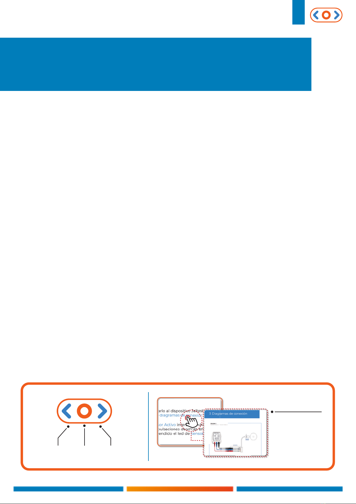
device through multipin cable kit according to the IMAGE 4 of the connection
diagram section (it is possible to connect multipins to the ECU or to an intermediate
connector).
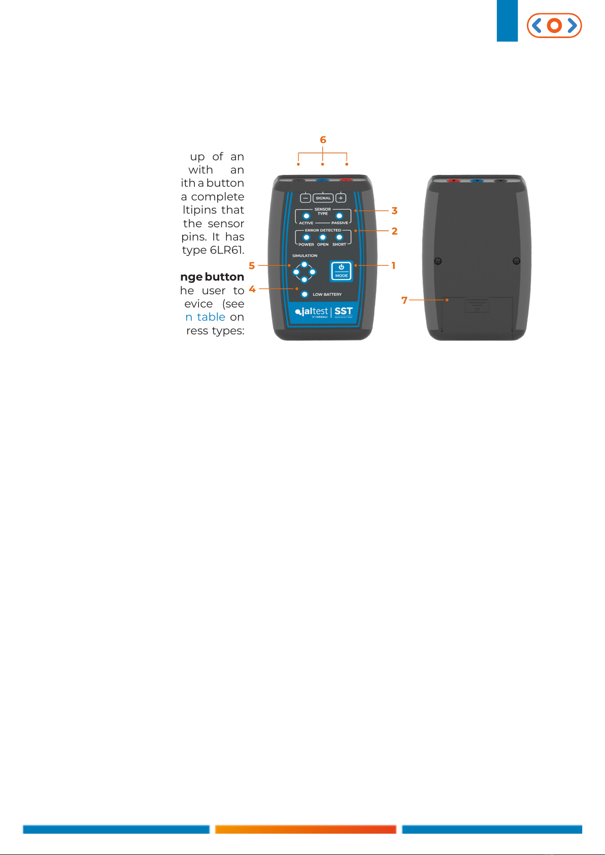
2Turn on the device and go into Passive Sensor Simulation mode interacting with
the selection button of the mode (1) according to the presses described in the
function table on page 6. The Simulation and Passive sensor LEDs must be on, as
well as the LED of the errors that may appear.
Note: In case that the short circuit error appears in the Jaltest SST device, it can be removed once step
3is being carried out with just a short press of the selection button of the Mode.
3 Turn the ignition key of the vehicle to the ignition key position.
4 Use a diagnosis software to
verify that the ECU is reading
the speed simulated by the
device* (if you do not have a
diagnosis device, go to step 5).
If the ECU is not reading the
speed, perform short presses
of the selection button of the
mode (1) to reset the present
errors and adjust the signal
frequency gradually so that
it can be ready by the ECU.
In ABS sensors, the following
speeds are common:
* In case of not being able to connect to the system to perform the speed reading, try to connect with
the Jaltest SST device without going into the Passive Sensor Simulation mode. Once in the system, go
into the Passive Sensor Simulation mode to be able to read the speed values.
Notes:
- The speeds shown in the above table are merely indicative. The speed read depends on the vehicle
ECU and can vary signicantly depending on it.
- If the speed cannot be read with the connections of IMAGE 4of the connection diagram section, try
to invert the «+» and signal connections. If the speed is still not read, use the connections of IMAGE 5
(ground connection). As a last step, invert the «+» and signal connections.
No. of presses Approximate speed (km/h)
Start (go into Passive
Sensor Simulation mode)7
1 30
245
3 60
4 90

English 11
5Error check:
ٚThe power supply error LED lights up: There is an error in the sensor power su-
pply cable or the ECU does not provide the appropriate voltage for this cable
or the ECU connector in which we have connected to is not for a passive speed
sensor.
ٚThe short circuit error LED lights up: Short circuit to ground (chassis) or power
supply has occurred during the execution of the test.
3 Connection diagrams
IMAGE 1
Read mode - Active sensor
SIGNAL SIGNAL
GND
MULTIPINS
ACTIVE
SENSOR

English 13
IMAGE 4
Simulation mode - Passive Sensor
IMAGE 5
Simulation mode - Passive Sensor
Note: In most cases, the «+» multipin must
be connected to the pin with the highest
voltage concerning the ECU ground and the
«SIGNAL» multipin to the lowest voltage pin
concerning the ECU ground.
Note: In most cases, the «+» multipin must
be connected to the pin with the highest
voltage concerning the ECU ground and the
«SIGNAL» multipin to the lowest voltage pin
concerning the ECU ground.
SIGNAL
MULTIPINS
VEHICLE
CHASSIS
SIGNAL
MULTIPINS

English 14
4 Technical data
ٚDevice size: 118 x 79 x 32 mm
ٚCase size: 245 x 205 x 45 mm
ٚDevice weight: ~ 180 g
ٚComplete case weight: ~ 700 g
ٚAs security measure and in order to avoid the total battery discharge, the Jaltest
SST device automatically disconnects the power supply of the electronic
board when it detects an inactive period longer than 5 minutes.
ٚWorking temperature range: From -10 ºC until 40 ºC.
Table of contents
Other Cojali Test Equipment manuals