Cirs ZERDINE Inside 055A User manual

USER GUIDE
U
L
T
R
A
S
O
U
N
D
Q
U
A
L
I
T
Y
A
S
S
U
R
A
N
C
E
ZERDINE®
Inside
A registered trademark of CIRS
Three-Dimensional
Wire Test Object
Model 055A
900 Asbury Ave • Norfolk, Virginia 23513 • USA • Tel: 757-855-2765 • WWW.CIRSINC.COM

2

TABLE OF CONTENTS
1 OVERVIEW
1
2 INSTRUCTIONS FOR USE
2
HANDLING AND CARE
��������������������������������������������������������������� 2
USE OF REMOVABLE WATER WELL AND COVERS
������������������������������������ 3
GENERAL GUIDELINES FOR PERFORMING MEASUREMENTS
������������������������� 4
ESTABLISHING A BASELINE
��������������������������������������������������������� 4
3 TESTING PROCEDURES
5
DISTANCE
��������������������������������������������������������������������������� 5
PERIMETER, AREA AND VOLUME MEASUREMENTS
���������������������������������� 6
UNIFORMITY TESTING
��������������������������������������������������������������� 7
DEPTH OF PENETRATION
������������������������������������������������������������ 8
4 SPECIFICATIONS
9
5 ZERDINE®
10
6 WARRANTY
11

1
OVERVIEW
The Model 055A 3D Wire Test Object
is a sturdy, reliable phantom for as-
sessing volumetric measurement ac-
curacy in either 3D scanning systems
or free hand measurements.
The phantom is made of CIRS' pro-
prietary Zerdine®hydrogel polymer,
which has been formulated to provide
tissue mimicking properties including
compatibility with harmonic imag-
ing. To maximize phantom lifetime,
this gel is contained in a rugged ABS
plastic housing with a Saran-based
laminate membrane
CIRS is certified to ISO 13485:2016 standards. We have an in-house test facility to
measure acoustic properties of speed, attenuation and relative contrast. In addition,
two ultrasound systems are used to visually inspect each phantom. As a result,
every ultrasound phantom is subjected to rigorous testing both during manufacture
and upon completion. A Certificate of Compliance is issued with each phantom.
For further guidance on establishing a quality assurance program, you may want to
reference the accreditation programs established by the ACR and AIUM. You can
access this information at www.acr.org or www.aium.org. If additional information
is required, please call CIRS® technical service at 1-800-617-1177.
Spatial Measurements
with Model 055A
• Linear Distance
• Perimeter
• Area
• Volume (3D system or freehand
calculations
The phantom may also be used to determining
image uniformity and depth of penetration.

2
INSTRUCTIONS FOR USE
HANDLING AND CARE
With proper care, the Model 055A will withstand years of normal use. Below are
some guidelines to follow.
The scanning surface is the most important item on the phantom to protect. It can
withstand normal scanning pressure but DO NOT press on the scanning surface
with your fingernails or any other sharp objects. If the scanning surface becomes
damaged, seal the phantom in an airtight container and IMMEDIATELY contact
RMA Request form to 757-857-0523.
The phantom may be cleaned with mild soap and water ONLY. Avoid solvent-
based, alcohol-based, or abrasive cleaning agents.
For longest life, the phantom should be cleaned after each use and stored at room
temperature in the provided carry case. The primary concern is gel desiccation due
to loss of water vapor through the membrane. In addition, the thermal stresses
associated with the freeze/thaw cycle may cause the gel to crack or damage the
housing integrity, while extreme heat may accelerate water vapor transmission
through the membrane. To minimize desiccation, always store the phantom in the
air-tight carry case with the removable storage cover attached.
Inspect your phantom regularly for signs of damage and weight loss. If any notice-
able changes to the phantom are detected, return the phantom IMMEDIATELY for
repair or replacement.
At least once a year, weigh your phantom and compare to original
weight noted on certificate of compliance. If the phantom has lost
or gained more than 1% of its original weight and you notice a dif-
ference in vertical distance measurements, or if the scan surface
appears depressed, call CIRS at (800) 617-1177.
This product contains Zerdine, a non-flowing water-based, poly-
acrylamide material which is fully sealed within the phantom housing.
Zerdine contains trace amounts of the residual monomer acrylamide
CAS#79-06-1. There are no known hazards when the phantom
is used and stored as intended. Zerdine is fully cured and will not
leak from the housing. Damage to the integrity of the housing may
expose the user to trace amounts of acrylamide monomer. The
amount is not sufficient to pose an acute health risk, but it is still
advised to wear protective gloves if handling exposed Zerdine gel
due to the potential long-term hazards of the monomer. It is also
advisable to wash hands and all surfaces with soap and water after
handling exposed Zerdine gel.
3
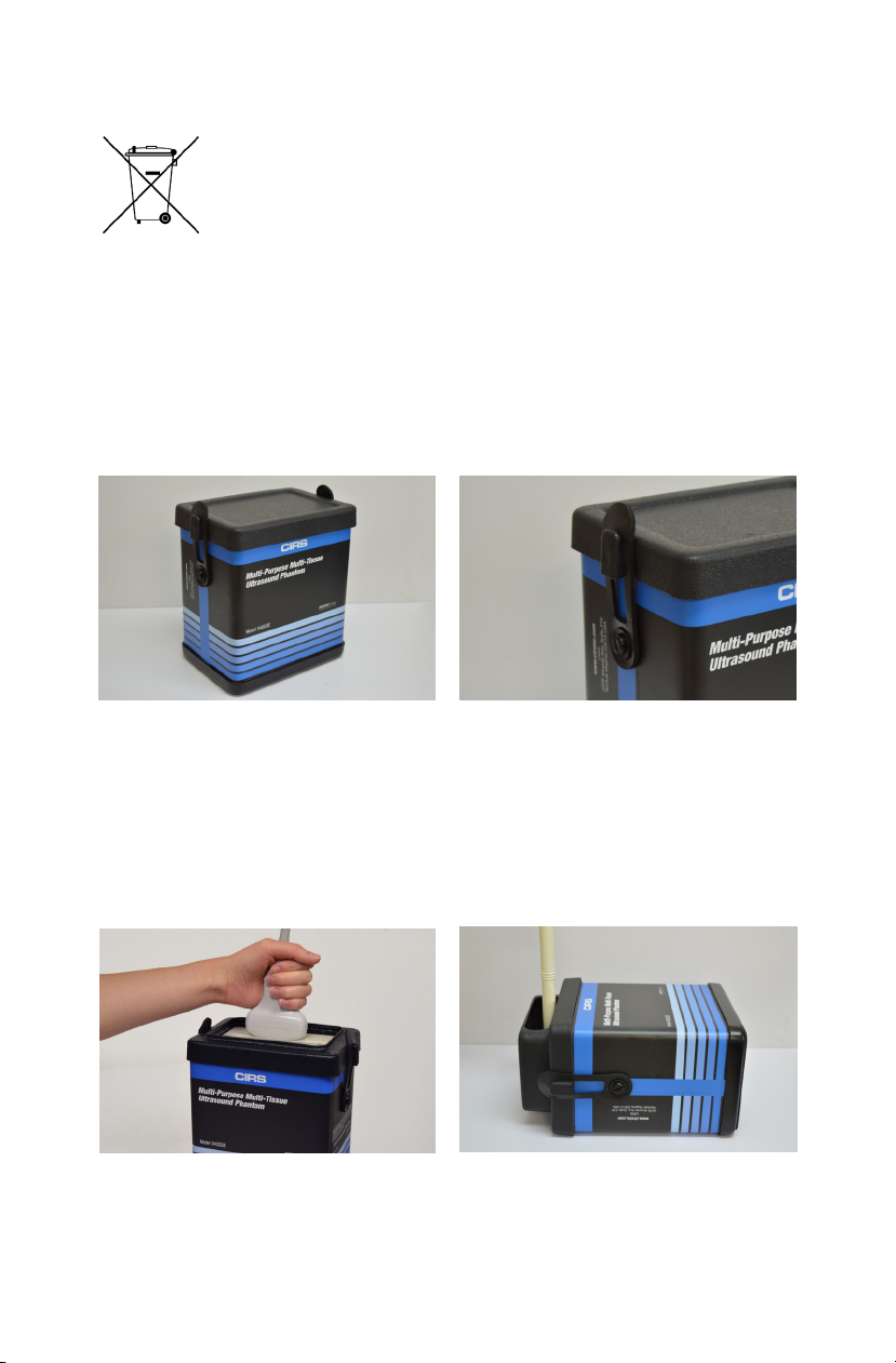
USE OF THE REMOVABLE WATER WELL AND COVERS
The phantom is shipped with the protective cover attached to the phantom. This
can be removed by stretching the elastic latches on either side of the phantom
up and off of the protective cover. The included water well and covers are easily
secured to the phantom with these same rubber latches. Simply place the water
well or cover on top of the phantom and stretch the elastic latches up and over the
attachment point on either side of the accessory.
Coupling gel can be applied directly to the scan surface. This option is best used
with linear transducers. For curved arrays, the water well may be attached and filled
with water to provide better coupling. Side Fire transducers can be particularly chal-
lenging to scan with a standard phantom. CIRS has designed a removable endo-
cavity cover for these transducers. When this accessory is attached, the phantom
should be placed on its back and the cover should be filled with water.
Cover on for storage Attach cover with latches
Water well for coupling curved probes Endocavity well
When finished scanning it is best to clean the scan surface of any water or coupling
gel and replace the protective cover.
Regulations regarding disposal of materials with trace acrylamide
monomer vary by locality. Contact your local authority for instruc-
tions. If assistance is desired in the proper disposal of this product,
including accessories and components, after its useful life, please
return to CIRS.
HANDLING AND CARE (CONTINUED)

4
GENERAL GUIDELINES FOR PERFORMING MEASUREMENTS
It is recommended that all measurements be performed at the most frequently used
imaging arrangements. The importance of these tests is to make sure the system
performance remains constant over an extended period of time. Measurements
may also be used to compare the performance of various setups of the same ma-
chine or to compare different machines in a quantitative manner.
The following are general steps for imaging all targets:
• Some wires will appear as short lines rather than dots. When using the
electronic calipers, always take measurements from a point on one echo
to the same point on the next, i.e., center to center. Otherwise, errors may
be introduced.
• If a convex probe is used, center the target within the scan plane in order to
minimize degradation and distortion introduced on the outer edges of the
probe.
• When assessing vertical distance measurements, DO NOT press on the
scanning surface. Pressure on the scanning surface causes the wires to
become temporarily displaced, making vertical distance measurements inac-
curate.
• When assessing horizontal distance accuracy, ensure the scan plane is
perpendicular to the horizontal target group. Rotation of the probe will result
in inaccurate distances.
• Always be sure the phantom is scanned while at room temperature. A
phantom just received may be colder or hotter than room temperature de-
pending on where it was stored during shipping. Temperature affects the
speed of sound and, ultimately, the perceived measurements. The phantom
should be stored at room temperature for at least 24 hours before use to
ensure its core temperature is correct.
• The most accurate measurements will be made with the phantom 22˚C ±
1˚C (70˚F–73˚F).
ESTABLISHING A BASELINE
Before performing routine quality assurance measurements, establish:
1. System settings for each measurement:
System setup can have a dramatic impact on the results obtained from quality as-
surance measurements. You must establish and record what system settings
should be used for each of the quality assurance tests. These same settings
should be used each time the test is performed. If not, then the conclusions
drawn may not be valid. CIRS recommends that you use the most commonly set-
tings for the type of probe tested- i.e. the liver preset values for an abdominal
probe- which are called a "normal" technique in the sections that follow.

5
2. Baseline measurements:
The first set of measurements taken will be the baseline measurements for the
combination of system settings and phantom. Record the system settings and
phantom serial number used to acquire each measurement along with
your measurement results. On subsequent scans, refer to the baseline results
to determine if the ultrasound system has drifted to an unacceptable level. It is
each facility's responsibility to establish the magnitude of drift allowed
before corrective action is warranted.
3. Allowable deviation from baseline measurements:
The difference between the original baseline measurements and subsequent
measurement should be calculated and recorded. At some point the difference
will be large enough that some action is required (call service, replace system,
etc.). Each facility needs to determine the action level for each test. You should
refer to the user’s manual of your ultrasound scanner and note the stated
accuracies of the system’s general imaging measurements. These stated ac-
curacies may greatly influence the conclusion made when evaluating the ultra
sound system. For example, if the measurement accuracy for your system
is 10% for distances up to 2 cm, the scanner may detect 2.0 cm as being any
where from 1.8 cm to 2.2 cm and still be functioning properly. The user is
responsible for establishing action levels.
4. Frequency of system assessment:
How often each system is evaluated is also up to each facility to deter
mine. CIRS recommends at least annually.
Reference the accreditation programs established by the ACR and AIUM at
www.acr.org or www.aium.org for further guidance on establishing a QA program.
TESTING PROCEDURES
The following sections outline procedures for performing routine quality control tests
with the imaging targets within the Model 055A. It may be useful to refer to the
target map, shown in the Specifications section, when reviewing these procedures.
DISTANCE
A vertical distance is defined as the distance along the axis of the beam. The verti-
cal wire targets are used to assess the accuracy of vertical distance measurements
as follows:
1. Apply coupling gel to the scanning surface or fill the water trough with tap
water.
2. Position the transducer in a vertical plane. (The wires should appear as dots,
not lines). Do not apply excessive pressure as this may temporarily
compress the target and skew the measurements.
3. Adjust the instrument settings (gain, TGC, output, etc.) as for a “normal”
technique. Record these settings for use on subsequent testing.

6
DISTANCE (CONT)
4. Align the probe so that all the vertical targets are displayed at their maximum
intensity level.
5. Freeze the image and obtain a hard copy.
6. Using electronic calipers, measure the distances between two wires at various
depths or align the echoes to the display markers for comparison.
7. Record these measurements.
8. Compare the measured values with the recorded baseline distances.
The horizontal target group is used to determine the accuracy of measurements
made perpendicular to the beam axis. The figure and table on page 9 provide a wire
target map that can be used to find the position of horizontal wire target. Testing is
performed as follows.
1. Fill the water trough with tap water.
2. Position the transducer in a vertical plane. (The wires should appear as dots,
not lines).
3. Adjust the instrument settings (gain, TGC, output, etc.) as for a “normal”
technique. Record these settings for use on subsequent testing.
4. Align the probe so that all the horizontal targets are displayed at their maximum
intensity level.
5. Freeze the image and obtain a hard copy.
6. Using electronic calipers, measure the distances between two wires along the
horizontal plane.
7. Record these measurements.
8. Compare the measured values with the known distances between the targets.
PERIMETER, AREA AND VOLUME MEASUREMENTS
Ultrasound imaging systems may detect differences in echogenicity of tissue struc-
tures and determine the dimensions of those structures through boundary detec-
tion. Spatial measurement data collected will give an indication of the accuracy that
the system is capable of. For more information see “Standard Methods for Calibra-
tion of 2-Dimensional and 3-Dimensional Spatial Measurement Capabilities of Pulse
Echo Ultrasound Imaging Systems.” AIUM: 2004.
Using the 2D shapes shown in the taget diagram on page 9, areas and perimeters
may be determined by connecting lines between the filament targets. Linear mea-
surements are taken from an image which is on a plane perpendicular to the line
targets.

7
To calculate a surface area or volume, an image is taken at a particular scan plane.
Using the calipers, the dimensions of the 2D shape are taken and the area is deter-
mined using the system’s algorithms. Next, perform a 3D scan of the line targets
with the scan planes parallel to each other and the scan direction perpendicular to
the axes of the line targets. The distance between the first scan plane and the last,
multiplied by the 2D area will give the 3D volume. This system calculated value may
then be compared to the actual volumes calculated from the rod lengths, and the
areas coincident with the 2D shape utilized.
Testing Procedure:
1. Place the phantom on a clean, flat surface with scanning surface #1
positioned for use.
2. Apply an adequate amount of low viscosity gel the scan surface.
3. Adjust the instrument settings (TGC, output, etc.) to establish baseline
values for a "normal" technique. If the bottom of the phantom is seen,
adjust the gain settings until the bottom of image goes entirely black. Record
these settings on the quality assurance record. These settings should be used
for subsequent testing.
4. Position the transducer over the line target group until a clear image is ob-
tained.
5. Freeze image and obtain a hard copy.
6. Measure the appropriate 2D dimensions
7. Perform a 3D scan.
8. Compare computed and system algorithm spatial measurements
9. All findings should be documented on the quality assurance record
UNIFORMITY TESTING
Uniformity is defined as the ability of the machine to display echoes of the same
magnitude and depth with equal brightness on the display. This is a good test to
ensure all crystals within the transducer are functioning, and is performed as
follows:
1. Apply coupling gel to the scanning surface or fill the water trough with tap water.
2. Position the transducer on the scanning surface in a region with a minimum
number of targets.
3. Adjust the instrument settings (gain, TGC, output, etc.) as for a “normal”
technique. Record these settings for use on subsequent testing.
4. Align the probe so that the targets are maximized.
5. Freeze the image and obtain a hard copy.
6. Observe the general appearance of the phantom. Note if all regions at the
same depth are displayed with the same intensity across the image.
7. Record your observations.

8
DEPTH OF PENETRATION TESTING
Depth of penetration, also called maximum depth of visualization or sensitivity, is the
greatest distance in a phantom for which echo signals caused by scattering in the
background material can be detected on the display. The depth of penetration is
determined by the frequency of the transducer, the attenuation of the medium being
imaged and the system settings. It is measured with the aid of the vertical distance
group of wire targets, as follows:
1. Apply coupling gel to the scanning surface or fill the water trough with tap water.
2. Position the transducer to acquire an image of a vertical plane target. (The
wires should appear as dots, not lines).
3. Adjust the instrument settings (gain, TGC, output, etc.) as for a “normal”
technique. Record these settings for use on subsequent testing.
4. Align the probe so that all the vertical targets are displayed at their maximum
intensity level.
5. While actively scanning, look to see where the backscattered echoes within the
background material disappear. Be careful not to confuse electronic noise with
the background backscattered echoes. Electronic noise will move but back-
scattered echoes will remain stationary while maintaining the transducer in a
fixed position.
6. Freeze the image.
7. With electronic calipers measure the distance between the scanning surface
and the last identifiable echoes due to scattering. Note: Usually the wires stay
visible even though the backscattered echoes are not. Remember to measure
the distance to the scattered echoes, not to the last visible wire.
8. Record this distance on a record sheet and compare with baseline depth.
9
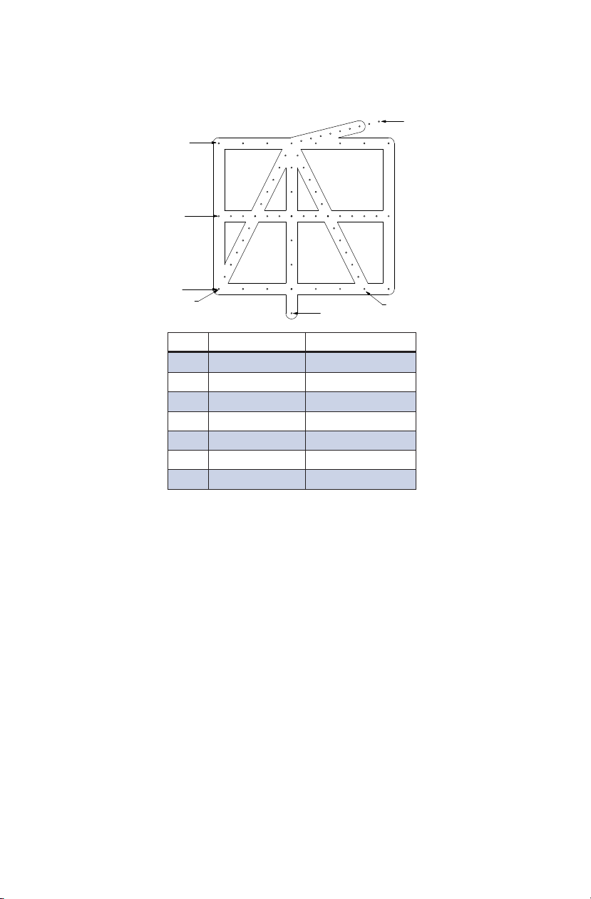
SPECIFICATIONS – MODEL 055A
TARGET LAYOUT
GROUP 1
GROUP 2
GROUP 3
GROUP 4
GROUP 5
GROUP 6 GROUP 7
GROUP STARTING POSITION (X, Y) SUBSEQUENT WIRE MOVES
1(0 cm, 0 cm) ∆x= 1 cm, ∆y= 0 cm
2(0 cm, 3 cm) ∆x= 0.5 cm, ∆y= 0 cm
3(0 cm, 6 cm) ∆x= 1 cm, ∆y= 0 cm
4(3 cm, 0 cm) ∆x= 0.4 cm, ∆y= -0.1 cm
5(3 cm, 0 cm) ∆x= 0 cm, ∆y= 1 cm
6(3 cm, 0 cm) ∆x= -0.25 cm, ∆y= 0.5 cm
7(3 cm, 0 cm) ∆x= 0.25 cm, ∆y= 0.5 cm
PHANTOM HOUSING
Material 1/4” Black ABS
Dimensions (Outer) 18 cm x 13 cm x 11 cm
Dimensions (Inside) 11.5 cm x 16.5 cm x 11 cm
Scanning Surface Saran-based Laminate
BACKGROUND MATERIAL
Material Zerdine®
Speed of Sound 1540 m/s
Other Compatible with harmonic imaging
WIRE TARGETS
Material Nylon monofilament
Diameter 0.1 mm
NEAR FIELD GROUP
Number of targets 10
Depth range 1 mm to 10 mm
Vertical distance between targets 1 mm

10
VERTICAL GROUP
Number of groups 3
Depth range 1-8 cm
Number of targets Groups 6 & 7: Qty. 13
Group 5: Qty. 8
Vertical distance between targets Groups 6 & 7: 0.5 cm
Group 5: 1 cm
HORIZONTAL GROUP
Number of groups 3
Depth of each group 1, 4, & 7 cm
Horizontal distance between targets Groups 1 & 3: 1 cm
Group 2: 0.5 cm
ACCESSORIES
• Removable water well (made of 1/8” ABS with a 14.4x9.5x1.0 cm opening)
• Removable endocavity cover (made of 1/8” ABS plastic)
• Removable storage cover (made of 1/8” ABS plastic)
• Carry case, Certificate of Compliance
• Model 055A User Guide
NOTES
All dimensions without tolerances are nominal
All measurements made at 22˚C ± 1˚C
ZERDINE®
The Model 055A is constructed from a patented, solid elastic material developed
at CIRS called Zerdine®. Zerdine, unlike other phantom materials on the market, is
not affected by changes in temperature. It can be subjected to boiling or freezing
conditions without sustaining significant damage. Zerdine is also more elastic than
other materials and allows more pressure to be applied to the scanning surface
without subsequent damage to the material. At normal room temperatures, Zerdine
will accurately simulate the ultrasound characteristics found in human liver tissue.
Specific proprietary fabrication procedures enable close control over the homoge-
neity of Zerdine and the reliability of its acoustic characteristics from batch to batch.
The speed of sound in Zerdine can be adjusted between 1430 and 1650 meters
per second. The acoustic attenuation can be adjusted between 0.05 dB/cm-MHz
and 1.50 dB/cm-MHz. The relation between the acoustic attenuation, A, and the
acoustic frequency, F, is of the form A = AoFnwith values of the power coefficient, n,
in the range of 0.8 to 1.10, indicating the proportional increase of the acoustic at-
tenuation with frequency. Backscatter characteristics can be adjusted through the
addition of predetermined amounts of calibrated scatter material, and are fully com-
patible with harmonic imaging. Zerdine can be molded into very intricate shapes,
and the material can be cured in layers allowing the production of “multi-tissue”
phantoms. Zerdine, like most other phantom materials, will desiccate if unprotect-
ed; thus, all phantoms must be stored properly. If stored in the case provided, your
phantom should last many years.

11
WARRANTY
All standard CIRS products and accessories are warranted by CIRS against defects
in material and workmanship for a period as specified below. During the warranty
period, the manufacturer will repair or, at its option, replace, at no charge, a product
containing such defect provided it is returned, transportation prepaid, to the manu-
facturer. Products repaired in warranty will be returned transportation prepaid.
There are no warranties, expressed or implied, including without limitation any im-
plied warranty of merchantability or fitness, which extend beyond the description on
the face hereof. This expressed warranty excludes coverage of, and does not pro-
vide relief for, incidental or consequential damages of any kind or nature, including
but not limited to loss of use, loss of sales or inconvenience. The exclusive remedy
of the purchaser is limited to repair, recalibration, or replacement of the product at
manufacturer’s option.
This warranty does not apply if the product, as determined by the manufacturer,
is defective because of normal wear, accident, misuse, or modification.
NON-WARRANTY SERVICE
If repairs or replacement not covered by this warranty are required, a repair estimate
will be submitted for approval before proceeding with said repair or replacement.
RETURNS
If you are not satisfied with your purchase for any reason, please contact your local
distributor prior to returning the product. Visit https://www.cirsinc.com/distributors/
to find your local distributor. If you purchased your product direct through CIRS, call
Customer Service at 800-617-1177, email [email protected], or fax an RMA request
form to 757-857-0523. CIRS staff will attempt to remedy the issue via phone or
email as soon as possible. If unable to correct the problem, a return material
authorization (RMA) number will be issued. Non-standard or “customized” products
may not be returned for refund or exchange unless such product is deemed by
CIRS not to comply with documented order specifications. You must return the
product to CIRS within 30 calendar days of the issuance of the RMA. All returns
should be packed in the original cases and or packaging and must include any
accessories, manuals and documentation that shipped with the product. The RMA
number must be clearly indicated on the outside of each returned package. CIRS
recommends that you use a carrier that offers shipment tracking for all returns and
insure the full value of your package so that you are completely protected if the
shipment is lost or damaged in transit. If you choose not to use a carrier that offers
tracking or insure the product, you will be responsible for any loss or damage to the
product during shipping. CIRS will not be responsible for lost or damaged return
shipments. Return freight and insurance is to be pre-paid.
WITH RMA NUMBER, ITEMS MAY BE RETURNED TO:
CIRS
Receiving
900 Asbury Ave,
Norfolk, Virginia, 23513 USA
PRODUCT WARRANTY PERIOD
Model 055A - 3D Wire Test Object 48 Months

12

©
2013 Computerized Imaging Reference Systems Inc. All rights reserved.
Specifications subject to change without notice.
Publication: 055A UG 032520
Computerized Imaging Reference Systems, Inc. has been
certified by UL DQS Inc. to (ISO) 13485:2016. Certificate
Registration No.10000905-MP2016.
COMPUTERIZED IMAGING
REFERENCE SYSTEMS, INC.
900 Asbury Ave
Norfolk, Virginia 23513 • USA
TOLL FREE 800.617.1177
TEL: 757.855.2765
FAX: 757.857.0523
EMAIL: [email protected]
www.cirsinc.com
Technical Assistance
1.800.617.1177
Table of contents
Other Cirs Test Equipment manuals


