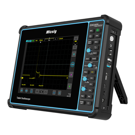
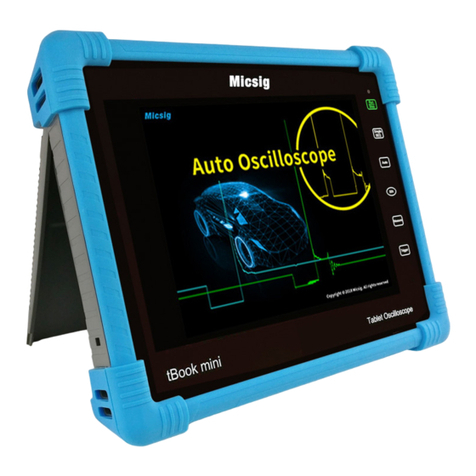
Micsig tbook mini Series User manual

Version Info
Version
Date
Remarks
V1.0
2016.10
V2.0
2020.04

Preface
Preface
Dear customers,
Congratulations! Thank you for buying Micsig instrument. Please read this manual carefully before use and
particularly pay attention to the “Safety Precautions”.
If you have read this manual, please keep it properly for future reference.
The information contained herein are furnished in an “as-is” state, and may be subject to change in future versions
without notice.

Table of Contents
i
Table of Contents
TABLE OF CONTENTS ................................................................................................................................................I
CHAPTER 1. SAFETY PRECAUTIONS .........................................................................................................................4
1.1 SAFETY PRECAUTIONS...........................................................................................................................................4
1.2 SAFETY TERMS AND SYMBOLS ..............................................................................................................................5
CHAPTER 2. QUICK START GUIDE OF OSCILLOSCOPE ...............................................................................................7
2.1 INSPECT PACKAGE CONTENTS...............................................................................................................................8
2.2 USE THE BRACKET ................................................................................................................................................8
2.3 REAR PANEL & SIDE PANEL ....................................................................................................................................9
2.4 FRONT PANEL........................................................................................................................................................9
2.5 POWER ON/OFF THE OSCILLOSCOPE.....................................................................................................................10
2.6 UNDERSTAND THE OSCILLOSCOPE DISPLAY INTERFACE......................................................................................11
2.7 INTRODUCTION BASIC OPERATIONS OF TOUCH SCREEN......................................................................................12
2.8 MOUSE OPERATION .............................................................................................................................................14
2.9 CONNECT PROBE TO THE OSCILLOSCOPE.............................................................................................................14
2.10 USE AUTO .........................................................................................................................................................15
2.11 LOAD FACTORY SETTINGS .................................................................................................................................17
2.12 USE AUTO-CALIBRATION...................................................................................................................................17
2.13 PASSIVE PROBE COMPENSATION .......................................................................................................................17
2.15 MODIFY THE LANGUAGE ...................................................................................................................................19
CHAPTER 3 HORIZONTAL SYSTEM.......................................................................................................................... 20
3.1 MOVE THE WAVEFORM HORIZONTALLY..............................................................................................................21
3.2 ADJUST THE HORIZONTAL TIME BASE (TIME/DIV)...............................................................................................21
3.3 PAN AND ZOOM SINGLE OR STOPPED ACQUISITIONS...........................................................................................23
3.4 ROLL, XY............................................................................................................................................................23
3.5 ZOOM MODE .......................................................................................................................................................26
CHAPTER 4 VERTICAL SYSTEM ............................................................................................................................... 29
4.1 OPEN/CLOSE WAVEFORM (CHANNEL, MATH, REFERENCE WAVEFORMS)...........................................................30
4.2 ADJUST VERTICAL SENSITIVITY ..........................................................................................................................32
4.3 ADJUST VERTICAL POSITION ...............................................................................................................................32
4.4 OPEN CHANNEL MENU........................................................................................................................................33
4.4.1 Set Channel Coupling...................................................................................................................................33
4.4.2 Set Bandwidth Limit ....................................................................................................................................35
4.4.3 Waveform Inversion ....................................................................................................................................36
4.4.4 Set Probe Type .............................................................................................................................................37
4.4.5 Set Probe Attenuation Coefficient ...............................................................................................................38
CHAPTER 5 TRIGGER SYSTEM ................................................................................................................................ 39
5.1 TRIGGER AND TRIGGER ADJUSTMENT .................................................................................................................40

ii
5.2 EDGE TRIGGER ....................................................................................................................................................45
5.3 PULSE WIDTH TRIGGER.......................................................................................................................................47
5.4 LOGIC TRIGGER...................................................................................................................................................51
5.5 NTH EDGE TRIGGER (OPTIONAL)........................................................................................................................53
5.6 RUNT TRIGGER (OPTIONAL)................................................................................................................................55
5.7 SLOPE TRIGGER...................................................................................................................................................56
5.8 TIMEOUT TRIGGER (OPTIONAL)..........................................................................................................................58
5.9 VIDEO TRIGGER ..................................................................................................................................................60
5.10 SERIAL BUS TRIGGER ........................................................................................................................................62
CHAPTER 6 ANALYSIS SYSTEM ............................................................................................................................... 63
6.1 AUTOMATIC MEASUREMENT ...............................................................................................................................64
6.2 FREQUENCY METER MEASUREMENT...................................................................................................................68
6.3 CURSOR...............................................................................................................................................................68
CHAPTER 7 SCREEN CAPTURE, MEMORY DEPTH AND WAVEFORM STORAGE........................................................ 72
7.1 SCREEN CAPTURE FUNCTION ..............................................................................................................................73
7.2 VIDEO RECORDING..............................................................................................................................................73
7.3 WAVEFORM STORAGE .........................................................................................................................................74
CHAPTER 8 MATH AND REFERENCE....................................................................................................................... 79
8.1 DUAL WAVEFORM CALCULATION .......................................................................................................................80
8.2 FFT MEASUREMENT ...........................................................................................................................................82
8.3 REFERENCE WAVEFORM CALL ............................................................................................................................85
CHAPTER 9 DISPLAY SETTINGS AND FUNCTION BUTTONS ..................................................................................... 88
9.1 WAVEFORM SETTINGS.........................................................................................................................................89
9.2 GRATICULE SETTING ...........................................................................................................................................89
9.3 PERSISTENCE SETTING ........................................................................................................................................89
9.4 HORIZONTAL EXPANSION CENTER.......................................................................................................................90
9.5 TIME BASE MODE SELECTION .............................................................................................................................90
9.6 WAVEFORM REFRESH RATE (HIGH REFRESH MODE).............................................................................................91
9.7 RUN/STOP AND SINGLE SEQ ...............................................................................................................................91
9.8 AUTO...................................................................................................................................................................91
9.9 MEASUREMENT ...................................................................................................................................................92
9.10 TRIGGER............................................................................................................................................................92
9.11 HOME ................................................................................................................................................................92
CHAPTER 10 SAMPLING SYSTEM ........................................................................................................................... 93
10.1 SAMPLING OVERVIEW .......................................................................................................................................94
10.2 RUN/STOP KEY AND SINGLE SEQ KEY..............................................................................................................96
10.3 SELECT SAMPLING MODE..................................................................................................................................97
10.4 RECORD LENGTH AND SAMPLING RATE ..........................................................................................................100
CHAPTER 11 HOMEPAGE FUNCTIONS.................................................................................................................. 102
11.1 OSCILLOSCOPE (SEE CHAPTERS 2~13).............................................................................................................103
Table of Contents
iii
11.2 CONTACT US ....................................................................................................................................................103
11.3 FILE MANAGER ...............................................................................................................................................103
11.4 SETTINGS.........................................................................................................................................................104
11.5 QUICKGUIDE....................................................................................................................................................109
11.6 PHOTO .............................................................................................................................................................109
11.7 VIDEO..............................................................................................................................................................111
11.8 TIME................................................................................................................................................................112
11.9 SHUTDOWN、LOCK SCREEN AND UNLOCK.............................................................................................................112
CHAPTER 12 SERIAL BUS TRIGGER AND DECODE (OPTIONAL) ............................................................................. 115
12.1 UART (RS232/RS422/RS485) BUS TRIGGER AND DECODE ...........................................................................117
12.2 LIN BUS TRIGGER AND DECODE .....................................................................................................................122
12.3 CAN BUS TRIGGER AND DECODE ...................................................................................................................126
12.4 SPI BUS TRIGGER AND DECODE ......................................................................................................................129
12.5 I2C BUS TRIGGER AND DECODE......................................................................................................................133
12.6 ARINC429 BUS TRIGGER AND DECODE .........................................................................................................136
12.7 1553B BUS TRIGGER AND DECODE .................................................................................................................139
CHAPTER 13 REMOTE CONTROL.......................................................................................................................... 143
13.1 HOST COMPUTER.............................................................................................................................................144
13.1.1 Installation of Host Computer Software ..................................................................................................144
13.1.2 Connection of Host Computer .................................................................................................................144
13.1.3 Main Interface Introduction ....................................................................................................................145
13.1.4 Operation Interface Introduction ............................................................................................................146
13.1.5 Storage and View of Pictures and Videos ................................................................................................146
13.2 MOBILE REMOTE CONTROL ............................................................................................................................147
13.3 FTP .................................................................................................................................................................148
13.4 SCPI................................................................................................................................................................151
CHAPTER 14 REFERENCE ..................................................................................................................................... 152
14.1 MEASUREMENT CATEGORY .............................................................................................................................153
14.2 POLLUTION DEGREE........................................................................................................................................153
14.3 SOFTWARE AND FIRMWARE UPDATES ..............................................................................................................154
CHAPTER 15 TROUBLESHOOTING........................................................................................................................ 155
CHAPTER 16 SERVICES AND SUPPORT ................................................................................................................. 158
ANNEX ................................................................................................................................................................ 159
ANNEX A:TECHNICAL SPECIFICATIONS ................................................................................................................159
ANNEX B:MAINTENANCE AND CARE OF OSCILLOSCOPE.........................................................................................164
ANNEX C: ACCESSORIES .........................................................................................................................................165

4
Chapter 1. Safety Precautions
1.1 Safety Precautions
The following safety precautions must be understood to avoid personal injury and prevent damage to this product
or any products connected to it. To avoid possible safety hazards, it is essential to follow these precautions while
using this product.
⚫Only professionally trained personnel can operate the maintenance procedure.
⚫Avoid fire and personal injury.
⚫Use proper power cord. Use only the power cord specified for this product and certified for the
country/region of use.
⚫Connect and disconnect probes properly. Connect the instrument probe correctly, and its ground terminal
is ground phase. Do not connect or disconnect probes or test leads while they are connected to a voltage
source. Disconnect the probe input and the probe reference lead from the circuit under test before
disconnecting the probe from the measurement product.
⚫Ground the product. To avoid electric shock, the instrument grounding conductor must be connected
to earth ground.
⚫Observe all terminal ratings. To avoid fire or shock hazard, observe all rating and markings on the product.
Consult the product manual for further information of ratings before making connections to the product.
⚫User correct probes. To avoid excessive electric shock, use only correct rated probes for any measurement.
⚫Disconnect AC power. The adapter can be disconnected from AC power and the user must be able to access
the adapter at any time.
⚫Do not operate without covers. Do not operate the product with covers or panels removed.
⚫Do not operate with suspected failures. If you suspect that there is damage to this product, have it inspected
by service personnel designated by Micsig.
⚫Use adapter correctly. Supply power or charge the equipment by power adapter designated by Micsig, and
charge the battery according to the recommended charging cycle.
⚫Avoid exposed circuitry. Do not touch exposed connections and components when power is present.
⚫Provide proper ventilation.
⚫Do not operate in wet/damp conditions.
⚫Do not operate in a flammable and explosive atmosphere.
⚫Keep product surfaces clean and dry.
⚫The disturbance test of all models complies with Class A standards, based on

Chapter 1. Safety Precautions
5
EN61326:1997+A1+A2+A3, but do not meet Class B standards.
Measurement Category
The TO1000 series oscilloscope is intended to be used for measurements in Measurement Category I.
Measurement Category Definition
Measurement category I is for measurements performed on circuits not directly connected to the MAINS. Examples
are measurements on circuits not derived from MAINS, and specially protected (internal) MAINS derived circuits. In
the latter case, transient stresses are variable; for that reason, the user must understand the transient withstand capability
of the equipment.
Warning:
IEC Measurement Category. Under IEC Category I mounting conditions, the input terminal can be connected to
the circuit terminal with a maximum line voltage of 300Vrms. To avoid the risk of electric shock, the input
terminal should not be connected to the circuit with a line voltage greater than 300Vrms. Instantaneous
overvoltage is present in circuits that are isolated from the mains supply. The TO1000 series digital oscilloscope
is designed to safely withstand sporadic transient overvoltage up to 1000Vpk. Do not use this equipment for any
measurements in circuits where the instantaneous overvoltage exceeds this value.
1.2 Safety Terms and Symbols
Terms in the manual
These terms may appear in this manual:
Warning. Warning statements indicate conditions or practices that could result in injury or loss of life.
Caution. Caution statements indicate conditions or practices that could result in damage to this product
or other property.
Terms on the product
These terms may appear on the product:
Danger indicates an injury hazard immediately accessible as you read the marking.
Warning indicates an injury hazard not immediately accessible as you read the marking.
Caution indicates a hazard to this product or other properties.
Symbols on the product
The following symbols may appear on the product:

6
Hazardous Voltage Caution Refer to Manual Protective Ground Terminal
Chassis Ground Measurement Ground Terminal
Please read the following safety precautions to avoid personal injury and prevent damage to this product
or any products connected to it. To avoid possible hazards, this product can only be used within the
specified scope.
Warning
If the instrument input port is connected to a circuit with the peak voltage higher than 42V or the power exceeding
4800VA, to avoid electric shock or fire:
⚫User only insulated voltage probes supplied with the instrument, or the equivalent product indicated in the
schedule.
⚫Before use, inspect voltage probes, test leads, and accessories for mechanical damage and replace when
damaged.
⚫Remove voltage probes and accessories not in use.
⚫Plug the battery charger into the AC outlet before connecting it to the instrument.

Chapter 2. Quick Start Guide of Oscilloscope
7
Chapter 2. Quick Start Guide of Oscilloscope
This chapter contains checks and operations of the oscilloscope. You are recommended to read them carefully to
understand appearance, power on/off, settings and related calibration requirements of the tBook mini series
oscilloscope.
⚫Inspect package contents
⚫Use bracket
⚫Rear panel & side panel
⚫Front panel
⚫Power on/off the oscilloscope
⚫Understand the oscilloscope display interface
⚫Introduction to basic operations of oscilloscope
⚫Mouse operation
⚫Connect probe to the oscilloscope
⚫Use automatic
⚫Use factory settings
⚫Use auto-calibration
⚫Passive probe compensation
⚫Modify the language

8
2.1 Inspect Package Contents
When you open package after receipt, please check the instrument according to the following steps.
1) Inspect if there is any damage caused by transportation
If the package or foam is found to be severely damaged, please retain it until the instrument and accessories
pass the electrical and mechanical properties test.
2) Inspect the accessories
A detailed description is given in “Annex C” of this manual. You can refer it to check if the accessories are
complete. If the accessories are missing or damaged, please contact Micsig’s agent or local office.
3) Inspect the instrument
If any damage to oscilloscope is found by the appearance inspection or it fails to pass the performance test,
please contact Micsig’s agent or local office. If the instrument is damaged due to transportation, please retain
the package and contact the transportation company or Micsig’s agent, and Micsig will make arrangement.
2.2 Use the Bracket
Put the front panel of the oscilloscope flatly on the table. Use your two index fingers to hold the underside of the
bracket and open the bracket by slightly upwards force, as shown in Figure 2-1.
Figure 2-1 Open Bracket

Chapter 2. Quick Start Guide of Oscilloscope
9
2.3 Rear panel & side panel
Figure 2-2 Rear panel & side Panel
2.4 Front Panel
Figure 2-3 Front Panel of Tablet Oscilloscope

10
Touch button
Description
Run/Stop: Touch to start/Stop acquisition
Single SEQ: Touch to trigger on a single waveform
Auto:Touch to activate automatic waveform setup
Note: Automatic setup requires the frequency of the test signal to be at least
20Hz if the signal is sinusoidal. Otherwise, automatic setup may fail and the
quick parameter measurement function displayed in the menu will also be
unavailable
50%:Touch to set:
⚫The channel zero point quickly returns to the center of the screen
⚫The trigger position quickly returns to the center of the screen
⚫Trigger level quickly returns to the center of waveform
⚫The cursor automatically adjusts to the center of the screen on both
sides, horizontal or vertical
Measure:Touch to turn on / off measurement menu
Trigger:Touch to turn on / off trigger menu
Home:Touch to return to the homepage
Table 2-1 Description of Oscilloscope Front Panel
2.5 Power on/off the Oscilloscope
Power on/off the oscilloscope
First time start
⚫Connect power adapter to the oscilloscope, and the oscilloscope should not be pressed on the adapter cable.
⚫Press the power button to start the instrument.
Power on
⚫Press the power button to start the instrument while ensuring it is connected to a power supply.
Power off
⚫Press the power button , go to power-off interface, and click to turn off the instrument.
⚫Long press the power button for forced power-off of the instrument.
Caution: Forced power-off may result in loss of unsaved data, please use with caution.

Chapter 2. Quick Start Guide of Oscilloscope
11
2.6 Understand the Oscilloscope Display Interface
This section provides a brief introduction and description of the tBook mini Series oscilloscope user’s interface.
After reading this section, you can be familiar with the oscilloscope display interface content within the shortest
possible time. The specific settings and adjustments will be detailed in subsequent chapters and sections. The
following items may appear on the screen at a given time but not all items are visible. The oscilloscope interface
is shown in Figure 2-4.
Figure 2-4 Oscilloscope Interface Display
No.
Description
1
Micsig logo
2
Oscilloscope status, including RUN, STOP, WAIT, AUTO
3
Trigger point
4
Sampling rate, memory depth
5
The area in “[]” indicates the position of waveform displayed on the screen throughout the memory
depth
6
Delay time, the time at which the center line of the waveform display area is relative to the trigger

12
No.
Description
point
7
Center line of waveform display area
8
Memory depth indicatrix
9
Current trigger type indication
10
Current trigger source, trigger level
11
Trigger level indicator
12
CH1、CH2、CH3、CH4 cchannel icons and vertical sensitivity icon. Tap the channel icons to
open channels and corresponding channel menu, or close channels, operate in a loop; Tap mV or
V to adjust the vertical sensitivity of channels; Display the vertical sensitivity of channels; Display
the sampling mode
13
Trigger level adjustment, press on the button to modify the trigger level through upward and
downward movements
14
Display areas of USB-PC connection, USB connection, battery level, time etc.
15
Switch to MATH and REF channel
16
Horizontal and vertical cursors open and close
17
Current channel selection. Click to pop up the current channel switching menu to switch the current
channel.
18
Horizontal time base control icon. Tap the left/right time base buttons to adjust the horizontal time
base of the waveform. Tap the time base to turn on the time base knob and turn the knob to adjust
the time base.
19
Quick save. Tap to quickly save the waveform as a reference waveform.
20
Fine adjustment button. Tap the button to finely adjust the last operation, including waveform
position, trigger level position, trigger point and cursor position.
21
Waveform display area displays information such as waveforms, cursors, and related waveform
measurements.
22
Channel indicator can indicate the zero-level position of the open channel.
Table 2-1 Description of Oscilloscope Display Interface
2.7 Introduction Basic Operations of Touch Screen
The tBook mini Series oscilloscope operates mainly by tap, swipe, single-finger drag, and multi-finger drag.

Chapter 2. Quick Start Guide of Oscilloscope
13
Figure 2-5 Basic Operations of tBook mini series Oscilloscope
Tap
Tap button on the touch screen to activate the corresponding menu and function. Tap any blank space on the
screen to exit the menu.
Swipe
Single-finger swipe: to open/close menus, including main menu, shortcut menu button and other channel menu
operations. For example, the main menu is opened as shown in Figure 2-6. The closing method is the opposite of
the opening method.
Figure 2-6 Slide out of Main Menu
Tap the options in the main menu to enter the corresponding submenu.

14
The opening methods of channel menu and math menu are slightly different from that of the main menu. Tap the
channel icon and math icon to open the corresponding menu.
Three-finger slide: to quickly turn on/off Zoom. Refer to “3.5 Zoom Mode” for details.
Four-fingers slide: for quick screen capture. Refer to “7.1 Screen Capture Function” for details.
Single-finger drag: For coarse adjustments of vertical position, trigger point, trigger level, cursor, etc. of the
waveform. Refer to “3.1 Horizontal Move Waveform” and “4.3 Adjust Vertical Position” for details.
2.8 Mouse Operation
Connect the mouse to the “USB Host” interface, then operate the oscilloscope with the mouse. The menu will
pop up with the right mouse button. The left mouse button has the same function as the finger touch, and the
horizontal time base can be adjusted by rolling the mouse wheel. The right mouse button menu is shown in Figure
2-7.
Figure 2-7 Mouse Cursor
2.9 Connect Probe to the Oscilloscope
1) Connect the probe to the oscilloscope channel BNC connector.
2) Connect the retractable tip on the probe to the circuit point or measured equipment. Be sure to connect the
probe ground wire to the ground point of the circuit.
Maximum input voltage of the analog input
Category I 300Vrms, 400Vpk.

Chapter 2. Quick Start Guide of Oscilloscope
15
2.10 Use Auto
Once the oscilloscope is properly connected and a valid signal is input, tap the Auto Set button to
quickly configure the oscilloscope to be the best display effects for the input signal.
Auto is divided into Auto Set and Auto Range. It is defaulted as Auto Set.6
Auto Set — Single-time auto, and each time press “Auto”, the screen displays “Auto” in the upper left corner.
The oscilloscope can automatically adjust the vertical scale, horizontal scale and trigger setting according to the
amplitude and frequency of signals, adjust the waveform to the appropriate size and display the input signal.
After adjustments, exit from the auto set, the “Auto” in the upper left corner disappears.
Channels may be automatically opened. Any channel greater or less than the threshold level can be opened or
closed automatically according to the set threshold level. The threshold level can be settable.
Source can be automatically triggered, and the triggered source channel can be automatically set to select priority
to the current signal or to the maximum signal.
Open the main menu. Tap “Auto” to open the auto set menu, including channel open/close setting, threshold
voltage setting and trigger source setting.
Figure 2-9 Open Auto Set
Automatic configuration includes: single channel and multiple channels; automatic adjustment of the horizontal
time base, vertical sensitivity and trigger level of signal; the oscilloscope waveform is inverted off, the bandwidth
limit sets to full bandwidth, it sets as DC coupling mode, the sampling mode is normal; the trigger type is set to
edge trigger and the trigger mode is automatic.
Note: The application of Auto Set requires that the frequency of measured signal is no less than 20Hz, the
duty ratio is greater than 1% and the amplitude is at least 2mVpp. If these parameter ranges are exceeded,
Auto Set will fail.

16
Figure 2-10 Auto Set Waveform
Auto Range - Continuously automatic, the oscilloscope continuously adjusts the vertical scale, horizontal time
base and trigger level in a real-time manner according to the magnitude and frequency of signal. It is defaulted
as off and needs to be opened in the menu. This function is mutually exclusive with “Auto Set”.
Open the main menu and tap “Auto” to open the auto range menu for the corresponding settings. When the
oscilloscope auto range function is turned on, the oscilloscope will automatically set various parameters,
including: vertical scale, horizontal time base, trigger level, etc. When the signal is connected, these parameters
will automatically change, and the signal does not need to be operated again after the change. The oscilloscope
will automatically recognize and make the appropriate changes.
⚫Auto range: Turn the auto range function on or off
⚫Vertical scale: Turn on the vertical scale automatic adjustment function;
⚫Horizontal time base: Turn on the horizontal time base automatic adjustment function;
⚫Trigger level: Turns on the auto-adjust trigger level function.
Figure 2-11 Open Auto Range
Auto Range is usually more useful than Auto Set under the following situations:
1) It can analyze signals subject to dynamic changes.

Chapter 2. Quick Start Guide of Oscilloscope
17
2) It can quickly view several continuous signals without adjusting the oscilloscope. This function is very
useful if you need to use two probes at the same time, or if you can only use the probe with one hand
because the other hand is full.
3) Control the automatic adjustment setting of the oscilloscope.
2.11 Load Factory Settings
Open the main menu, tap “User Settings” to enter the user setting page. Tap “Factory Settings” and the dialog
box for loading factory settings will pop-up. Press “OK” and load the factory settings. The dialog box for loading
factory settings is shown in Figure 2-12.
Figure 2-12 Load Factory Settings
2.12 Use Auto-calibration
Open the main menu, tap “User Settings” to enter the user setting page. Tap “Auto Calibration” to enter the auto-
calibration mode. When the auto-calibration function is active, the upper left corner of the screen displays
“Calibrating” in red, and after calibrating is finished, the word in red disappears. When the temperature changes
largely, the auto-calibration function can make the oscilloscope maintain the highest accuracy of measurement.
⚫Auto-calibration should be done without probe.
⚫Auto-calibration process takes about two minutes.
⚫If the temperature changes above 10℃, we recommended users perform the auto-calibration.
2.13 Passive Probe Compensation
Before connecting to any channels, users should make a probe compensation to ensure the probe match the input
channel. The probe without compensation will lead to larger measurement errors or mistakes. Probe
compensation can optimize the signal path and make measurement more accurate. If the temperature changes 10℃
or above, this program must run to ensure the measurement accuracy.
Probe compensation may be conducted in the following steps:
1) First, connect the oscilloscope probe to CH1. If a hook head is used, make sure that it is in good
connection with the probe.
2) Connect the probe to the calibration output signal terminal and connect the probe ground to the ground
terminal. As shown in Figure 2-13.
This manual suits for next models
5
Table of contents
Other Micsig Test Equipment manuals

Micsig
Micsig DP750-100 User manual

Micsig
Micsig SATO1000 Series User manual

Micsig
Micsig DP750 User manual

Micsig
Micsig MDP Series User manual

Micsig
Micsig ATO1000 Series User manual

Micsig
Micsig DP5013 User manual

Micsig
Micsig Smart Series User manual

Micsig
Micsig MS300 Series User manual

Micsig
Micsig CP2100A User manual

Micsig
Micsig ATO Series User manual