Cisco MERAKI MT20 User manual

MT20 Installation Guide - Open/Close Detection
Overview
The Cisco Meraki MT20 is a cloud managed Intrusion Detection sensor that is exceptionally simple to configure and deploy due to its integration with the Meraki
dashboard and the use of BLE technology. The MT family eliminates the complex and costly setup required by traditional solutions by removing the limitations of
placement of these sensors.
About this Guide
This guide provides instructions on how to install and configure your MT20 Environmental Sensors.
Product Overview
Physical Specifications
Dimensions
Main device: 81.2mm x 39.7mm x 19.5mm
(length x width x height)
Magnet cover: 59.5mm x 12mm x 13.35mm
(length x width x height)
Power • 1x AA Alkaline Battery
•Rating: 1.5V; 100mA
Operating Environment •Temperature: 0°C - 55°C (32F - 131F)
•Relative Humidity: 0 - 95% RH
Hardware
• Multicolor, multifunction status LED
• General purpose button
• Reset button
• Main device and a magnet enclosure
1
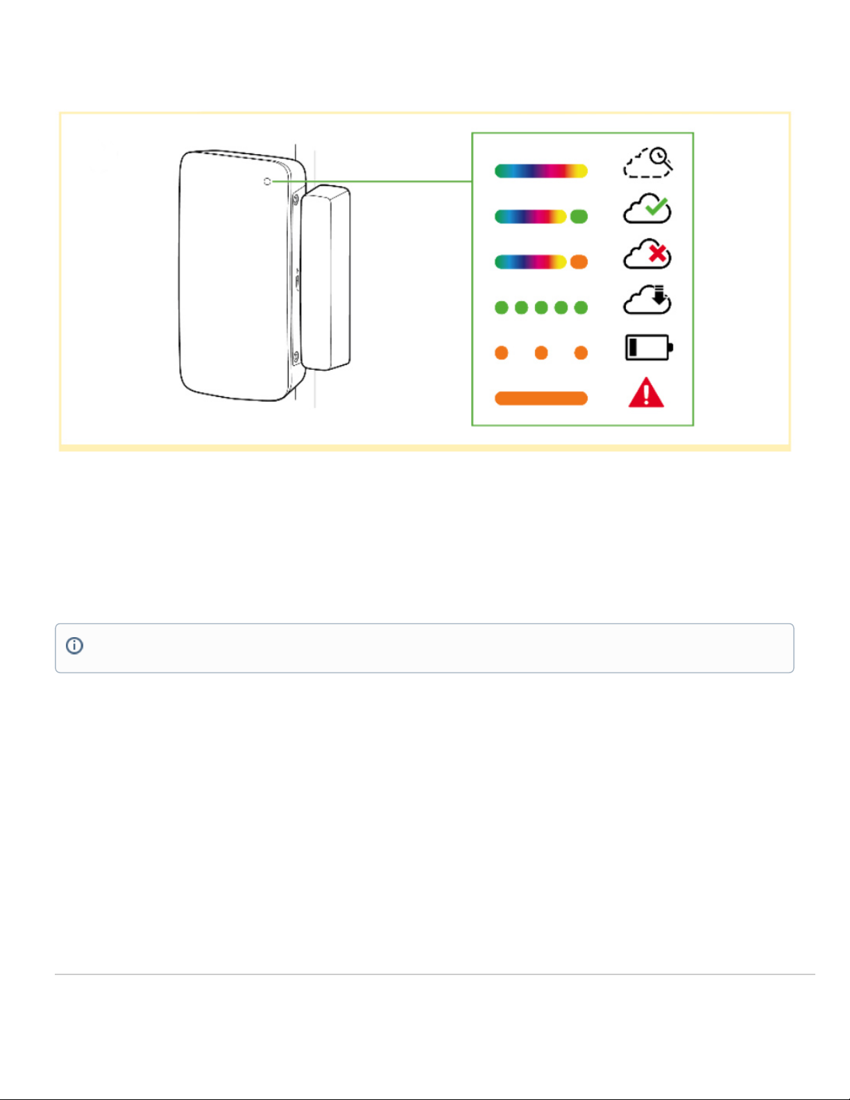
LED Indicators
• Rainbow - MT is initializing or looking for a gateway.
• Solid Green (for n seconds) - Connected to a gateway.
• Solid Amber (for n seconds) - MT could not find a gateway to connect
• Flashing Green - MT is upgrading its firmware
• Flashing Amber - MT is running on a low battery.
General Purpose Button
The MT20 has a pinhole general purpose button on the top which allows you to wake up the sensor and test if it is able to connect to a gateway.
Factory Reset Button
Next to the battery compartment, there is a pinhole button to factory reset the sensor. If the button is pressed and held for at least five seconds and then
released, the sensor will reboot and it will be restored to its original factory settings by deleting all configuration information stored on the unit.
To conserve battery life, the LEDs on the MT20 don't always remain ON.
2
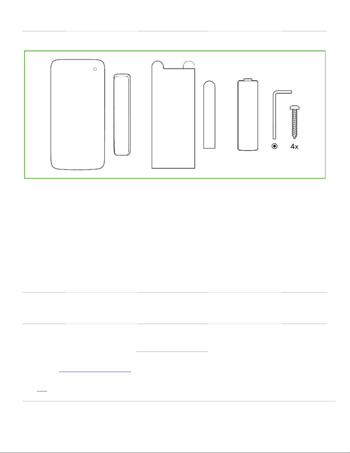
Package Contents
Unit MT20-HW
Guides Quick Install Guide
Battery 1x AA Batteries
Magnet Enclosure Cover with a magnet attached to the bottom
Mounting equipment
1x Torx key
4x Screws
2x VHB Tape
Pre-Installation Preparation
You should complete the following steps before going on-site to perform an installation
Configure Your Network in Dashboard
The following is a brief overview only of the steps required to add an MT12 to your network. For detailed instructions about creating, configuring and managing
Meraki Sensor networks, refer to the online documentation (https://documentation.meraki.com/MT).
1. Login to http://dashboard.meraki.com. If this is your first time, create a new account.
2. Find the network to which you plan to add your sensor or create a new network.
3. Add the sensors to your network. You will need your Meraki order number (found on your invoice) or the serial
number of each sensor, which looks like Qxxx-xxxx-xxxx, and is found on the back of the unit or included in the
3
box.
4. Add the gateway (MV or MR) to the same network as the sensor.
List of Compatible Gateways:
MV MR
MV12(W/NE), MV22(X), MV32, MV72(X) MR36, MR45, MR44, MR46, MR46E, MR55, MR56, MR76, MR86
Minimum Firmware Version
MV
MT sensors can only connect to a compatible MV gateway running MV 4.8+. Please refer to Managing Firmware Upgrade to schedule an upgrade.
MR
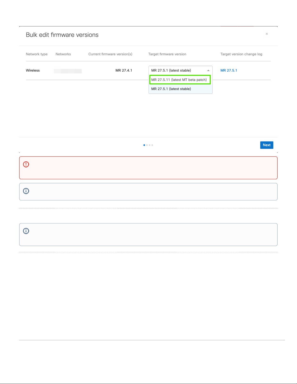
In order to use a compatible MR device as a gateway for MT sensors, the Network in question should be set to MR27.5.11. This is a patch release that is based
off MR 27.5.1(latest stable) with additional support for MT sensors. Please refer to Managing Firmware Upgrade to schedule an upgrade.
NOTE: Make sure the gateway is in the same network and is online and operational.
MV Set up Instructions and MR Set up Instructions.
WARNING: Environmental Sensors are only supported with 2nd Gen MV Cameras and Wifi 6 Compatible APs
4
Installation Instructions
Choosing Your Mounting Location
As MT sensors rely on a gateway for connectivity to the Dashboard, while choosing a mounting location, make sure that a working compatible gateway is in
range of the sensor.
Some ideal mounting locations:
1. Doors and rack enclosures with a flushed frame: In this scenario, the installation is pretty straightforward and either mounting options can be used.
2. Sliding Doors: The MT20 can also be installed on sliding doors with up to 2 cm of Z-axis separation between the sensor and the magnet enclosure.
MR 27.5.1 release DOES NOT SUPPORT MT sensors. The network HAS to be running 27.5.11 for MT sensors to be connected to the eligible MR
gateways.
MR 27.5.11 version will only show up on Organization that has at least 1 MT sensor claimed in a network.
NOTE: Each MT20 comes with an instruction manual within the box. This manual contains detailed step by step guide and images to assist you with
the physical installation of the sensor.
5

The picture above shows the ideal mounting locations and also the acceptable distance for the most accurate results.
For most mounting scenarios, the MT20 has flexible options to provide quick and simple mounting. The instructions are as follows:
1. Start by removing the battery compartment cover by unscrewing it from the grey panel. Insert the AA battery into the battery compartment.
2. In order to mount the sensors there are 2 options:
NOTE: If the magnet is too close to the sensor or has been incorrectly placed, the sensor will be put in an alerting mode for Device Tampering
Detected. Make sure there’s at least a 5 mm gap between the sensor and the magnet.
6
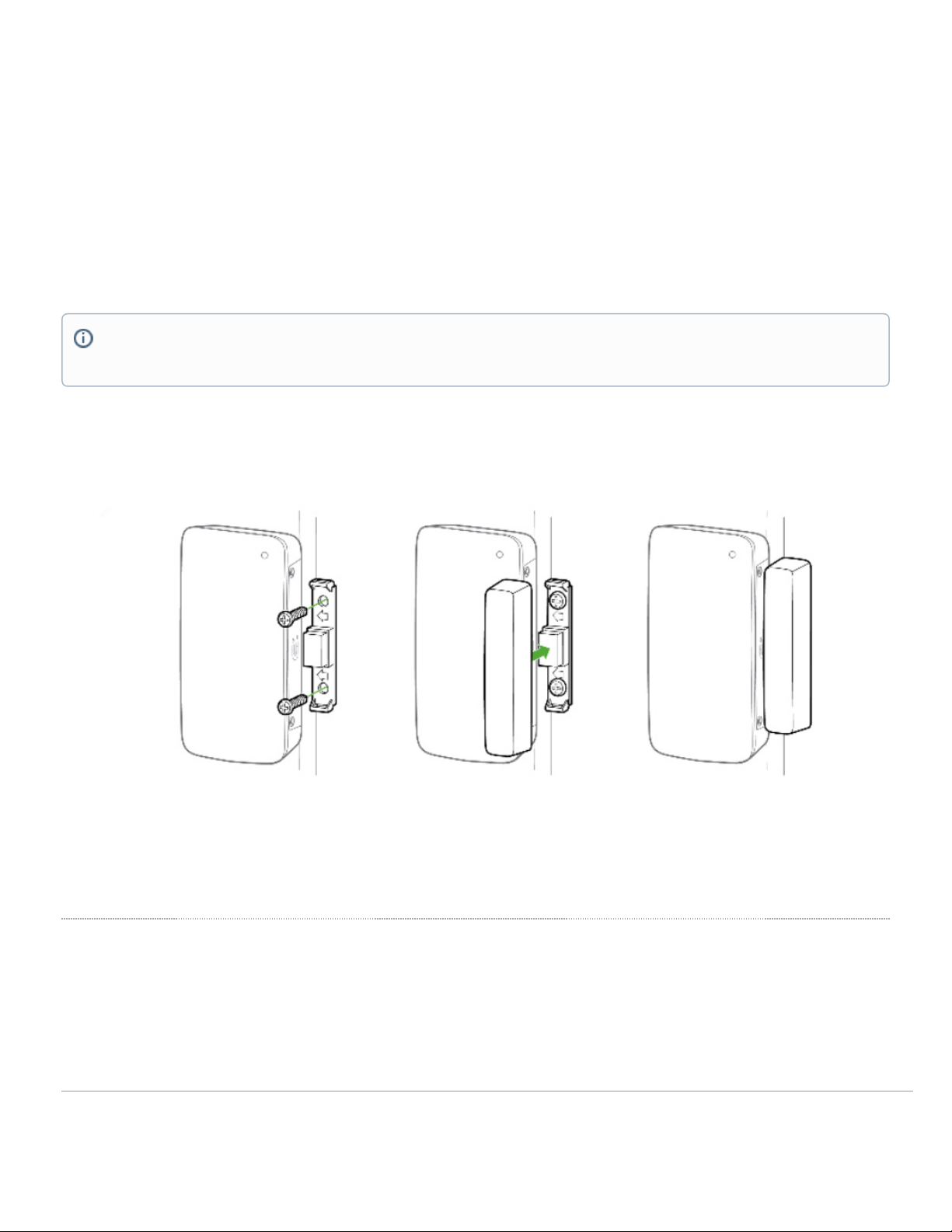
Screws Mount
As shown in the picture below, once the battery cover is removed, the 2 screws can be inserted through the holes. After the screws are tightly fitted, the battery
compartment needs to be closed to ensure security of the sensor. Ideally, the main sensor body should be mounted on the door. Make sure that the grey panel
with the Magnet icon faces towards the outer edge of the door where you intend to install the magnet cover.
The magnet cover can also be removed to access the holes for the screw. Ideally, this part should be mounted on the door frame. Make sure the grey side with
the magnet symbol, faces towards the sensor.
VHB Tape
Alternatively, the 2 double sided VHB tape can also be used for a less permanent solution. Note this option doesn’t ensure the security of the sensor.
Incorrect Installation
In order for the MT20 to detect the correct magnetic field, the Main sensor body and the magnet needs to be aligned properly.
NOTE: The grey panel on the sensor and the magnet cover should be facing towards each other. This orientation will always have the magnet poles
in opposite directions.
7
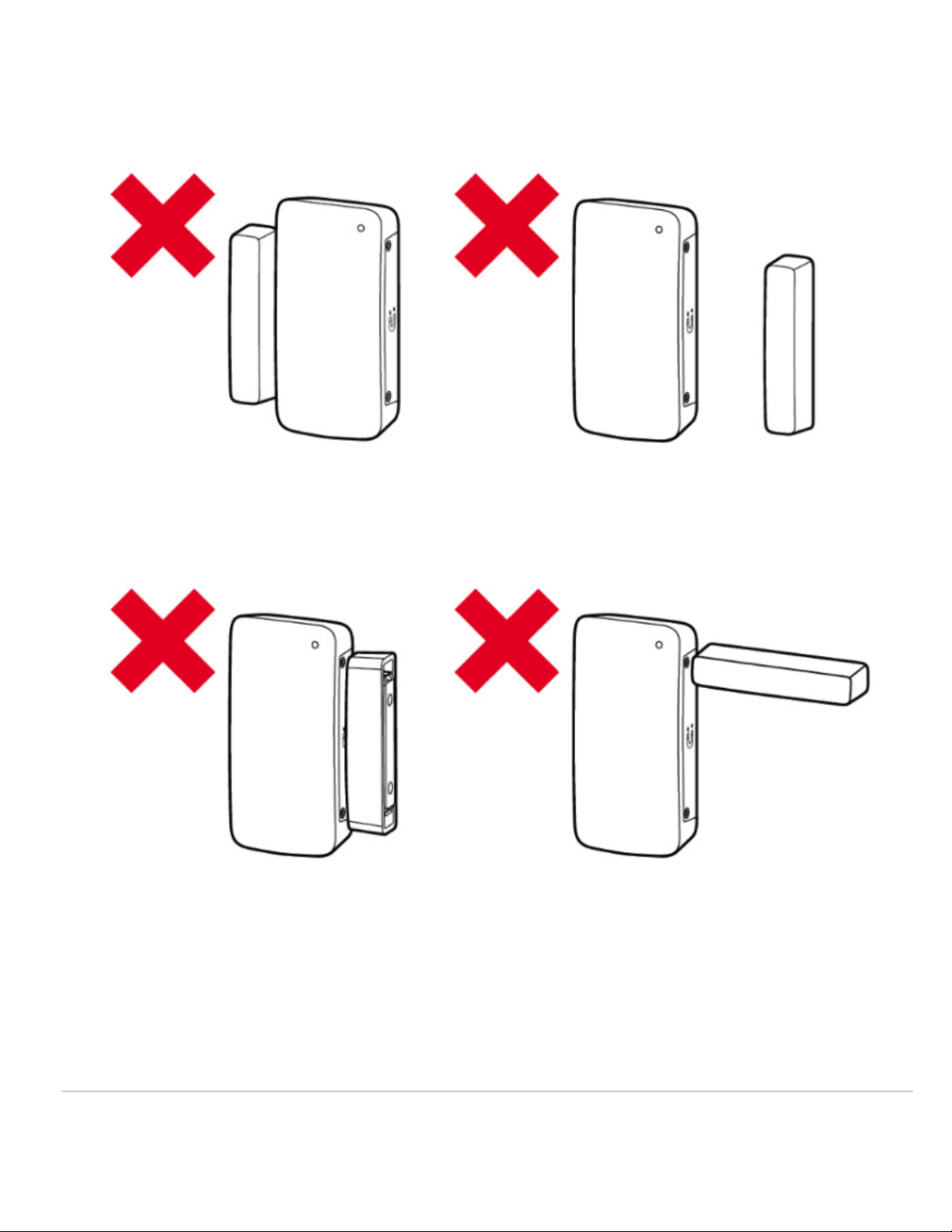
As noted in the illustration above, all of these orientations are an example of an incorrect installation and can result in inaccurate readings.
8

Support and Additional Information
If issues are encountered with device installation or additional help is required, contact Meraki Support by logging in to dashboard.meraki.com and opening a
case by visiting the Get Help section.
For additional information on Meraki hardware and for other installation guides, please refer to documentation.meraki.com.
WARNING: Magnet polarity can also cause incorrect readings. Do make sure when installing the magnet cover, the arrows on the plastic is facing
the sensor body
9
Table of contents
Other Cisco MERAKI Accessories manuals


