manuals.online logo
Brands
  1. Home
  2. •
  3. Brands
  4. •
  5. Cisco
  6. •
  7. Network Router
  8. •
  9. Cisco 12000 GSR Series Service manual

Cisco 12000 GSR Series Service manual

This manual suits for next models

3

Other Cisco Network Router manuals

Cisco ASR 9000 Series Instruction Manual

Cisco

Cisco ASR 9000 Series Instruction Manual

Cisco CPA2501 User manual

Cisco

Cisco CPA2501 User manual

Cisco 2600 Series Manual

Cisco

Cisco 2600 Series Manual

Cisco 2611XM User manual

Cisco

Cisco 2611XM User manual

Cisco 1751 User manual

Cisco

Cisco 1751 User manual

Cisco vEdge 100 Manual

Cisco

Cisco vEdge 100 Manual

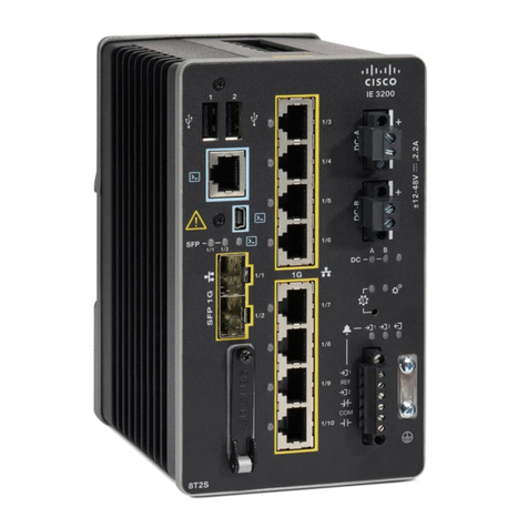
Cisco 805 Series Operating and safety instructions
Cisco

Cisco 805 Series Operating and safety instructions

Cisco ASR 5000 Series User manual

Cisco

Cisco ASR 5000 Series User manual

Cisco Linksys WET610N User manual

Cisco

Cisco Linksys WET610N User manual

Cisco 1005 Installation guide

Cisco

Cisco 1005 Installation guide

Cisco 520-T1 - Small Business Pro SR Secure Router User manual

Cisco

Cisco 520-T1 - Small Business Pro SR Secure Router User manual

Cisco XR 12000 User manual

Cisco

Cisco XR 12000 User manual

Cisco 1811W - Integrated Services Router Wireless User manual

Cisco

Cisco 1811W - Integrated Services Router Wireless User manual

Cisco Cisco 12416 Operator's manual

Cisco

Cisco Cisco 12416 Operator's manual

Cisco 500 Series Original instructions

Cisco

Cisco 500 Series Original instructions

Cisco 1750 Manual

Cisco

Cisco 1750 Manual

Cisco ASR 903 User manual

Cisco

Cisco ASR 903 User manual

Cisco 2811 - Voice Security Bundle Router Installation instructions

Cisco

Cisco 2811 - Voice Security Bundle Router Installation instructions

Cisco ASR 9000 Series Installation manual

Cisco

Cisco ASR 9000 Series Installation manual

Cisco ASR 900 Series User manual

Cisco

Cisco ASR 900 Series User manual

Cisco WS-C3550-12G User manual

Cisco

Cisco WS-C3550-12G User manual

Cisco WRT54G2 Linksys User manual

Cisco

Cisco WRT54G2 Linksys User manual

Cisco WRT54GR User manual

Cisco

Cisco WRT54GR User manual

Cisco Linksys X2000 User manual

Cisco

Cisco Linksys X2000 User manual

Popular Network Router manuals by other brands

TRENDnet TEW-435BRM - 54MBPS 802.11G Adsl Firewall M Quick installation guide

TRENDnet

TRENDnet TEW-435BRM - 54MBPS 802.11G Adsl Firewall M Quick installation guide

Siemens SIMOTICS CONNECT 400 manual

Siemens

Siemens SIMOTICS CONNECT 400 manual

Alfa Network ADS-R02 Specifications

Alfa Network

Alfa Network ADS-R02 Specifications

Barracuda Networks Link Balancer quick start guide

Barracuda Networks

Barracuda Networks Link Balancer quick start guide

ZyXEL Communications ES-2024PWR Support notes

ZyXEL Communications

ZyXEL Communications ES-2024PWR Support notes

HPE FlexNetwork 5510 HI Series Openflow configuration guide

HPE

HPE FlexNetwork 5510 HI Series Openflow configuration guide

Allied Telesis AT-AR236E quick start guide

Allied Telesis

Allied Telesis AT-AR236E quick start guide

ADTRAN NetVanta 3458-PoE quick start

ADTRAN

ADTRAN NetVanta 3458-PoE quick start

C&H Technologies EM405-8 manual

C&H Technologies

C&H Technologies EM405-8 manual

Huawei WiFi Mesh 3 Product description

Huawei

Huawei WiFi Mesh 3 Product description

Addonics Technologies ISC8P2G-S Quick install guide

Addonics Technologies

Addonics Technologies ISC8P2G-S Quick install guide

Atel W02 Arch+ Faqs

Atel

Atel W02 Arch+ Faqs

Allnet ALL0333AU user guide

Allnet

Allnet ALL0333AU user guide

Sercomm Genesis OC3505D Quick installation guide

Sercomm

Sercomm Genesis OC3505D Quick installation guide

Billion BIPAC 5102 Series user manual

Billion

Billion BIPAC 5102 Series user manual

TP-Link TD-8817 QIG

TP-Link

TP-Link TD-8817 QIG

Motorola MR1900 user guide

Motorola

Motorola MR1900 user guide

NETGEAR WGE101 Reference manual

NETGEAR

NETGEAR WGE101 Reference manual

manuals.online logo
manuals.online logoBrands
  • About & Mission
  • Contact us
  • Privacy Policy
  • Terms and Conditions

Copyright 2025 Manuals.Online. All Rights Reserved.

Course Reference Material
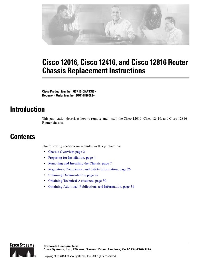
Cisco Installing and Maintaining Routers Part 4: 12000 GSR Series and XS5032 Modules
NETg course 20614
Copyright © 2000 National Education Training Group, Inc.
All rights reserved. No part of the material protected by this copyright may be reproduced or utilized in any
form or by any means, electronic or mechanical, including photocopying, recording, broadcasting, or by any
information storage and retrieval system, without permission in writing from National Education Training
Group, Inc.
Skill Builder is a registered trademark of National Education Training Group, Inc. All other trademarks
referenced are the trademark, service mark, or registered trademark of their respective holders. National
Education Training Group, Inc. is not affiliated with any company or any other product or vendor mentioned
in this course and its accompanying materials.
The software and technology used to implement this course contain trade secrets that NETG considers to be
confidential and proprietary information, and your right to use this material is subject to the restrictions in the
license agreement under which you obtained it.
Contents
Objectives
Cisco 12000 Series GSR Routers
Cisco 12000 Router Installation
Cisco 12008 GSR
Cisco 12008 GSR: Installation
20614 Cisco Installing and Maintaining Routers Part 4: 12000 GSR Series and XS5032 Modules
1
Cisco 12004 GSR
Cisco 12000 Series GSR Line Cards
Cisco 12000 Series GSR: Troubleshooting
Catalyst 3000 and 5000 Router Modules
Catalyst 3000 Router: Installation
Catalyst 5000 RSM: Installation
Catalyst 5000 RSM: Configuring
Procedures
Cisco 12000 Series GSR Routers
Cisco 12000 Router Installation
Cisco 12008 GSR: Installation
Catalyst 3000 and 5000 Router Modules
Catalyst 3000 Router: Installation
Catalyst 5000 RSM: Installation
Glossary
Alphabetical List of Terms
Objectives
Total number of objectives = 41
Note: (ULT) is the unit, lesson, topic ID.
Cisco 12000 Series GSR Routers
Major Components and Optional Modules
12000 Series Routers: Overview (ULT 112): Identify the 12000 series Gigabit Switch Routers (GSRs).• GRP (ULT 113): Identify the characteristics of the 12000 series Gigabit Route Processor (GRP).• Alarm Card (ULT 114): Identify the functions and features of the alarm card.• Switch Fabric (ULT 115): Identify the characteristics of the switch fabric.• Power Supplies (ULT 116): Identify the Cisco 12000 power supplies.• Blower Modules (ULT 117): Identify the features of the Cisco 12000 series cooling system.•
20614 Cisco Installing and Maintaining Routers Part 4: 12000 GSR Series and XS5032 Modules
2
Cisco 12000 Router Installation
Preinstallation Guidelines (ULT 121): Identify preinstallation guidelines for the Cisco 12000 router.• AC−Input Power Supply: Installing (ULT 122): Sequence the steps involved in installing an AC−input
power supply.
•
DC−Input Power Supply: Installing (ULT 123): Sequence the steps involved in installing a DC−input
power supply.
•
System Startup (ULT 124): Sequence the steps involved in starting the Cisco 12012 system.• Installed Interfaces: Configuring (ULT 125): Identify the function of the setup command in configuring
installed interfaces.
•
Cisco 12008 GSR
Cisco 12008 GSR: Overview (ULT 131): Identify the characteristics of the Cisco 12008 Gigabit Switch
Router (GSR).
•
Power and Airflow Guidelines (ULT 132): Identify guidelines for power and airflow safety.• Cable Management System (ULT 133): Identify the functions and features of the cable management
system.
•
Cisco 12008 GSR: Installation
Upper Card Cage: Removing Cards (ULT 141): Identify the steps involved in removing cards from the
upper card cage.
•
Power Supply: Removing (ULT 142): Sequence the steps involved in removing a 12008 GSR power
supply.
•
CSC Alarm−Monitoring Facilities (ULT 143): Identify the functions of the Cisco Systems Capital (CSC)
alarm−monitoring facility.
•
Cisco 12004 GSR
Cisco 12004 GSR: Overview (ULT 151): Identify the characteristics of the Cisco 12004 Gigabit Switch
Router.
•
Power Supply and Fan Tray (ULT 152): Identify the characteristics of the Cisco 12004 GSR power supply
and fan tray.
•
Cable Management (ULT 153): Identify the characteristics of the Cisco GSR cable management system.• Maintenance Bus (ULT 154): Identify the features of the Cisco 12004 maintenance bus.•
Cisco 12000 Series GSR Line Cards
Quad OC−3c/STM−1c Line Card (ULT 161): Identify the characteristics of the Quad OC−3c/STM−1c POS
line card.
•
OC−12c/STM−4c POS Line Card (ULT 162): Identify the characteristics of the OC−12c/STM−4c POS line
card.
•
OC−12c/STM−4c ATM Line Card (ULT 163): Identify the characteristics of the OC−12c/ STM−4c ATM
line card.
•
Line Card Memory (ULT 164): Identify the characteristics of line card onboard memory for Cisco 12000
routers.
•
20614 Cisco Installing and Maintaining Routers Part 4: 12000 GSR Series and XS5032 Modules
3
Cisco 12000 Series GSR: Troubleshooting
Startup Problems: Identifying (ULT 171): Identify Cisco 12000 Series Gigabit Switch Router (GSR) startup
problems.
•
Power Subsystem: Troubleshooting (ULT 172): Identify guidelines for troubleshooting the power
subsystem.
•
Processor Subsystem: Troubleshooting (ULT 173): Identify guidelines for troubleshooting the processor
subsystem.
•
Cooling Subsystem: Troubleshooting (ULT 174): Identify the guidelines for troubleshooting the 12000
series GSR cooling subsystem.
•
Cisco 12012: Running Diagnostics (ULT 175): Identify the steps involved in loading and running
diagnostics.
•
Catalyst 3000 and 5000 Router Modules
Catalyst 3000 Router: Installation
WS−X3011 Router Module: Overview (ULT 212): Identify the characteristics of the WS−X3011 router
module.
•
Router Card: Installing (ULT 213): Sequence the steps involved in connecting to the router console after
installing the router card.
•
Router Card: Network Connection (ULT 214): Identify the methods for connecting the router card to a
network.
•
Router Card: Configuring (ULT 215): Identify the steps involved in configuring the router card.•
Catalyst 5000 RSM: Installation
Catalyst 5000 Series Switch Architecture (ULT 221): Identify the characteristics of Catalyst 5000 series
switch architecture.
•
RSM: Installing (ULT 222): Identify the steps involved in installing the Route Switch Module (RSM).• RSM: Configuring for Inter−VLAN Routing (ULT 223): Identify guidelines for configuring the Route
Switch Module (RSM) for Inter−VLAN routing.
•
User Interface: RSM Command Modes (ULT 224): Identify each of the Route Switch Module (RSM)
command modes and their access methods.
•
Catalyst 5000 RSM: Configuring
Session Command: Using (ULT 231): Identify the functions of the session command.• RSM: Booting for the First Time (ULT 232): Identify the phases involved in booting the Route Switch
Module (RSM) for the first time.
•
RSM: Configuration Task List (ULT 233): Identify the different Route Switch Module (RSM)
configuration tasks for Inter−VLAN routing.
•
20614 Cisco Installing and Maintaining Routers Part 4: 12000 GSR Series and XS5032 Modules
4
Procedures
Cisco 12000 Series GSR Routers
Cisco 12000 Router Installation
AC−Input Power Supply: Installing
Attach an antistatic wrist strap to yourself and to one of the two ESD connection sockets.• Verify that the power supply power switch is in the STANDBY position.• Slide the power supply into the vacant bay, using two hands to support it.• Tighten the captive screw on the power supply faceplate.• Check that the AC power cord shipped with the power supply is the correct type for your site.• Plug the AC power cord into the power supply AC receptacle.• Clip the spring clip over the power cord plug to secure the plug in place.• Connect the other end of the AC power cord to the source AC receptacle.• Check that the source AC circuit breaker servicing the source AC receptacle is switched on.• Repeat the previous steps for the rest of the AC−input power supplies.• Turn the power supply switch on.•
DC−Input Power Supply: Installing
Attach an antistatic wrist strap to yourself and to one of the two ESD connection sockets on the front edges
of the upper card cage.
•
Check that the DC−input power supply switch is turned OFF (O).• Remove the front cover of the power supply from the power supply faceplate.• Remove the DC power cable bracket from the power supply faceplate.• Thread the source DC power cable leads up underneath the power supply handle.• Remove the nut and locking washer from the power supply threaded terminals and attach the source DC
power cable lug to the terminals.
•
Thread the circuit breaker external alarm leads up through the handle and attach them to the circuit breaker
alarm terminal block.
•
Position the source DC power cable leads underneath the power supply handle on the power supply
faceplate.
•
Place the DC power cable bracket over the power cable leads and secure the cable leads and the cable
bracket to the power supply faceplate.
•
Verify that the source DC wiring from the source DC breaker to the power supply is correct.• Replace the power supply front cover on the power supply faceplate.• Slide the power supply into the power supply bay.• Turn the captive jackscrew on the power supply faceplate clockwise to seat the power supply into the
backplane power connector.
•
Turn on the source DC circuit breakers servicing each DC−input power supply.•
20614 Cisco Installing and Maintaining Routers Part 4: 12000 GSR Series and XS5032 Modules
5
System Startup
Turn each system power switch to the ON position.• Check that the blower modules are operating by listening for them.• As the GRP boots, observe the GRP alphanumeric LED displays.• As the line cards boot, observe the alphanumeric LED indicators on each line card. Line cards boot from
left to right.
•
Boot the Cisco IOS software image you want to use by entering the appropriate b command at the ROM
monitor prompt (>).
•
Proceed with the setup facility or exit from setup and use configuration commands to configure global and
interface−specific parameters.
•
Cisco 12008 GSR: Installation
Upper Card Cage: Removing Cards
Attach an antistatic ESD wrist strap to your wrist.• Insert the banana jack into the ESD connection socket.• Write down each card type and card location.• Loosen the captive screws.• Pivot the two card ejector levers away from the faceplate to unseat the card.• Slide the card out of its slot.• Stack the removed card on an antistatic mat for ESD protection.•
Power Supply: Removing
Set the power to the off position.• Turn the captive screw on the power supply faceplate.• Pull the power supply unit halfway out of its bay.• Pull the power supply unit out completely.• Set the power supply unit aside in a safe place.•
Catalyst 3000 and 5000 Router Modules
Catalyst 3000 Router: Installation
20614 Cisco Installing and Maintaining Routers Part 4: 12000 GSR Series and XS5032 Modules
6
Router Card: Installing
Connect the switch to a computer or other data terminal equipment (DTE) device.• Connect the EIA−232 cable to the console, the DB−9 connector, on the switch.• Use the console configuration default settings for communication with the switch.• Power up the switch.• At the Greeting screen, press Return to enter the switch Main menu.• Press Ctrl and R from the switch Main menu to access the router card command−line interface (CLI).•
Router Card: Configuring
Connect an auxiliary terminal to the auxiliary port on your switch.• Turn on the power switch.• The switch Greeting screen appears. To access the router card from the Main menu, you press Ctrl and R.• Select Configuration from the Main menu.• Select Router Configuration from the Configuration menu.• Enter the box and port numbers and press the Enter key.• Select the required option from the Router Configuration menu.•
Catalyst 5000 RSM: Installation
RSM: Installing
Connect an ASCII terminal to a computer running terminal emulation software to the console port on the
Catalyst switch.
•
Use a screwdriver to loosen the captive installation screws and remove the module filler plate or the
existing module from the slot that you want to use.
•
Guide the RSM into the slot, aligning the sides of the RSM with the guides in the slot.• While keeping the module oriented horizontally, carefully slide it into the slot until its front panel makes
contact with the ejector levers.
•
Simultaneously push the left lever and the right lever in to fully seat the module in the backplane connector.• Tighten the captive installation screws on the left and right sides of the module.• Check the status of the module.• After verifying that the RSM is operational, enter the session mod/num command at the Cat5k>prompt.•
Glossary
Alphabetical List of Terms
(DTE) Data Terminal Equipment
20614 Cisco Installing and Maintaining Routers Part 4: 12000 GSR Series and XS5032 Modules
7
data terminal equipment. Device at the user end of a user−network interface that serves as a data source,
destination, or both. DTE connects to a data network through a DCE device (for example, a modem) and
typically uses clocking signals generated by the DCE. DTE includes such devices as computers, protocol
translators, and multiplexers.
10BaseT
10−Mbps baseband Ethernet specification using two pairs of twisted−pair cabling (Category 3, 4, or 5): one
pair for transmitting data and the other for receiving data. 10BaseT, which is part of the IEEE 802.3
specification, has a distance limit of approximately 328 feet (100 meters) per segment.
ASIC
Application Specific Integrated Circuit, a chip designed for a particular application. ASICs are built by
connecting existing circuit building blocks in new ways
ATM
Asynchronous Transfer Mode. International standard for cell relay in which multiple service types (such as
voice, video, or data) are conveyed in fixed−length (53−byte) cells. Fixed−length cells allow cell processing
to occur in hardware, thereby reducing transit delays. ATM is designed to take advantage of high−speed
transmission media such as E3, SONET, and T3.
Attachment Unit Interface (AUI)
attachment unit interface. IEEE 802.3 interface between an MAU and a NIC. The term AUI can also refer to
the rear panel port to which an AUI cable might attach. Also called transceiver cable.
AUI
Attachment Unit Interface
AWG
American Wire Gauge
Basic Rate Interface (BRI)
Basic Rate Interface. ISDN interface composed of two B channels and one D channel for circuit−switched
communication of voice, video, and data.
BNC
BNC coonector. Standard connector used to connect IEEE 802.3 10Base2 coaxial cable to an MAU.
BRI
Basic Rate Interface
BTU
20614 Cisco Installing and Maintaining Routers Part 4: 12000 GSR Series and XS5032 Modules
8
British thermal unit
buffer
A temporary storage area, usually in RAM.
C.S.C
Cisco Systems Capital
cage
a piece of hardware into which cards are installed
CEF
Cisco express forwarding
Challenge Handshake Authentication Protocol (CHAP)
Challenge Handshake Authentication Protocol. Security feature supported on lines using PPP encapsulation
that prevents unauthorized access. CHAP does not itself prevent unauthorized access, it merely identifies the
remote end. The router or access server then determines whether that user is allowed access.
Channel Service Unit (CSU)
channel service unit. Digital interface device that connects end−user equipment to the local digital telephone
loop. Often referred to together with DSU, as CSU/DSU.
channelized
Channelized modules are modules that can be broken down into time slots.
chassis
a box that houses main electonic components
Command Line Interface (CLI)
command line interface. Interface that allows the user to interact with the operating system by entering
commands and optional arguments. The UNIX operating system and DOS provide CLIs.
Compressed Serial Link Internet Protocol (CSLIP)
Compressed Serial Link Internet Protocol. Extension of SLIP that, when appropriate, allows just header
information to be sent across a SLIP connection, reducing overhead and increasing packet throughput on SLIP
lines.
CRC
20614 Cisco Installing and Maintaining Routers Part 4: 12000 GSR Series and XS5032 Modules
9
Cyclic redundancy check. Error−checking technique in which the frame recipient calculates a remainder by
dividing frame contents by a prime binary divisor and compares the calculated remainder to a value stored in
the frame by the sending node.
CSC
Clock and scheduler card
CSU
Channel Service Unit. Digital interface device that connects end−user equipment to the local digital telephone
loop. Often referred to together with DSU, as CSU/DSU.
CxBus
Cisco Extended Bus. Data bus for interface processors on Cisco 7000 series routers.
Data Circuit−terminating Equipment (DCE)
data circuit−terminating equipment (ITU−T expansion). Devices and connections of a communications
network that comprise the network end of the user−to−network interface. The DCE provides a physical
connection to the network, forwards traffic, and provides a clocking signal used to synchronize data
transmission between DCE and DTE devices. Modems and interface cards are examples of DCE.
Data Service Unit (DSU)
data service unit. Device used in digital transmission that adapts the physical interface on a DTE device to a
transmission facility such as T1 or E1. The DSU is also responsible for such functions as signal timing. Often
referred to together with CSU, as CSU/DSU.
DB−25 connector
A 25−pin connector used by parellel ports data bus connector
dBus
Diagnostic bus
dial−on−demand routing (DDR)
dial−on−demand routing. Technique whereby a router can automatically initiate and close a circuit−switched
session as transmitting stations demand. The router spoofs keepalives so that end stations treat the session as
active. DDR permits routing over ISDN or telephone lines using an external ISDN terminal adaptor or
modem.
DIMM
dual in−line memory module
DRAM
20614 Cisco Installing and Maintaining Routers Part 4: 12000 GSR Series and XS5032 Modules
10