Citel EXTender 1100 User manual

EXTender 1100A
Remote Module
Quick Installation Guide
Document Number: R-1100A-QIG Version: Rev AG

EXTender 1100A Remote Module: Quick Installation Guide 2
Copyright Information
© Copyright 2008 Citel plc All Rights Reserved
No part of this publication, including text, examples, diagrams, or icons, may be
reproduced, transmitted, or translated in any form or by any means, electronic,
mechanical, manual, optical, or otherwise, for any purpose, without prior written
permission of Citel Technologies.
Citel Technologies and its wholly-owned subsidiaries may have patents or
pending patents applications, trademarks, copyrights, or other intellectual
property rights covering subject matter in this publication. The furnishing of this
document does not give the recipient license to these patents, trademarks,
copyrights, or other intellectual properties.
Trademark Information
Citel, Citel Technologies, the Citel logo, Citel EXTender™, Citel IP PBXgateway
and The VoIP Migration Company are trademarks or registered trademarks of
Citel or its wholly-owned subsidiaries in the United States and other jurisdictions.
All other trademarks, registered trademarks, and service marks are the property
of their respective owners.
Accuracy Notice
Every effort was made to ensure that the information in this guide is complete
and accurate. However, Citel makes no representations or warranties, whether
expressed or implied, as to the accuracy or completeness of these materials and
shall not be liable for any loss or damage suffered or incurred as a result of
reliance upon or use of them.
Information in this publication is subject to change without notice. Citel
Technologies reserves the right, without prior notice, to change the equipment,
designs or documentation referred to herein as it considers necessary.
Your Responsibility for your System’s Security
Toll fraud is the use of your telecommunications system by an unauthorized
party, for example, persons other than your company’s employees, agents,
subcontractors, or persons working on your company’s behalf. Please note that
there may be a risk of toll fraud associated with your telecommunications system
and, if toll fraud occurs, it can result in substantial additional charges for your
telecommunications services.
You and your System Manager/System Administrator are responsible for the
security of your system such as programming and configuring your equipment to
prevent unauthorized use. The System Manager is also responsible for reading
all installation, instruction and system administration documents provided with
this product in order to understand fully the features that can introduce risk of toll
fraud and the steps that can be taken to reduce that risk. Citel Technologies does
not warrant that this product is immune from or will prevent unauthorized use of
common-carrier telecommunications services or facilities accessed through or
connected to it. Citel Technologies will not be responsible for any charges that
result from such authorized use.
Document Number: R-1100A-QIG Version: Rev AG © Copyright 2008 Citel plc All Rights Reserved
EXTender 1100A Remote Module: Quick Installation Guide 3
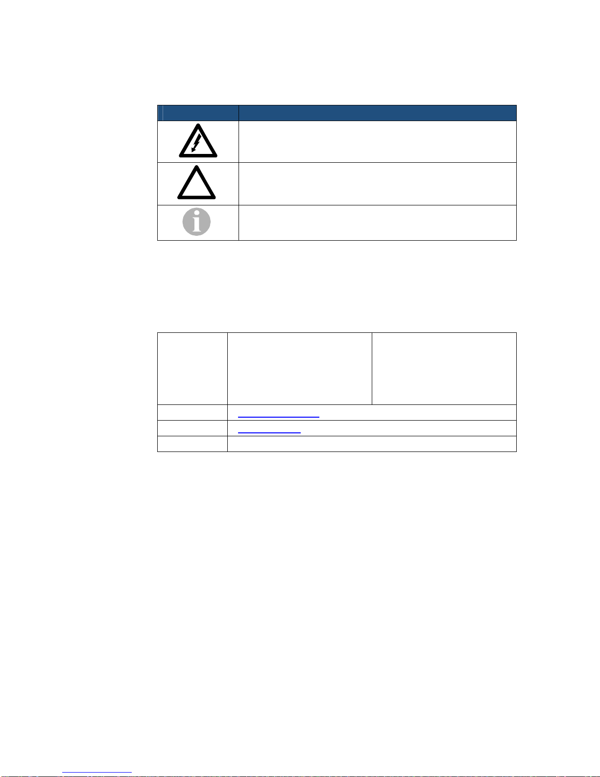
Symbols and Conventions
Important symbols and conventions used throughout this guide are shown below.
Icon Description
Important safety information. Ignoring this information may
lead to physical danger to people.
Information alerting you to potential loss of data or damage
to an application, system or device.
Highlights important information.
!
Contacting Citel Technologies
Mail Citel Technologies
3131 Elliott Avenue
Suite 250
Seattle, WA 98121
Citel Technologies
4 Wheatcroft Business Park
Landmere Lane
Edwalton
Nottinghamshire
NG12 4DG UK
Email support@citel.com
Web www.citel.com
Telephone +1 877 248 3587 – select the support option
© Copyright 2008 Citel plc All Rights Reserved

EXTender 1100A Remote Module: Quick Installation Guide 4
Products
The information contained within this document refers to the following products:
Part Number (North America) Description
E-1100A-SUC EXTender 1100A Switch Module
E-1100A-RUC EXTender 1100A Remote Module
Part Number (European Union) Description
E-1100A-SUC41 EU EXTender 1100A Switch Module
E-1100A-RUC41 EU EXTender 1100A Remote Module
Table 1: Product Part Numbers
Terms and Conventions
1. The EXTender 1100A Remote Module is a single-user communications
device that resides at the remote location and is referred to as the Remote
Module. The Remote Module connects to the Switch Module at the corporate
site thru the PSTN network.
2. The Management Console is the programming interface that is accessed
through the PC’s serial port and is referred to as the MC.
3. The Management Browser is the programming interface that is accessed
through a Web Browser and is referred to as the MB.
4. The Telephone Management Interface is the programming interface that is
accessed through the offline phone menus and is referred to as the TMI.
5. The corporate PBX (Private Branch Exchange), KTS (Key Telephone
System) and KSU (Key Service Unit) is the phone system currently used by
the client. For simplicity, they will be referred to as the PBX.
© Copyright 2008 Citel plc All Rights Reserved

EXTender 1100A Remote Module: Quick Installation Guide 5
Safety Information
WARNING – INPORTANT SAFETY INSTRUCTIONS
1. Read and make sure you understand all warnings and instructions, including
those marked on the product.
2. Do not install this product near water. For example, in a wet basement
location.
3. Do not install this product or associated wiring during a lightening storm.
4. Do not overload wall outlets as this can result in the risk of fire or electrical
shock.
5. Do not attach the power supply cord to building surfaces. Do not allow
anything to rest on the power cord. Do not place this product where anyone
can step on the cord.
6. Do not touch non-insulated wires or terminals unless the telephone wiring
has been disconnected at the network interface.
7. Unplug the product from the wall outlet before cleaning. Use a damp cloth for
cleaning. Do not use liquid or aerosol cleaners.
8. Do not operate the system if a chemical or gas leakage is suspected in the
area. Use a telephone located in another safe area to report the trouble.
9. The AC/DC adapter must only be used in an easily accessible outlet.
10. Do not open the PBXgateway or Remote. There are no user-serviceable
parts inside. Only an authorized technician should open the unit for required
maintenance or upgrading purposes.
Power Surges
Sudden surges in electrical current can damage sensitive equipment. To
reduce the risk of damage to your equipment caused by lightening strikes,
for example, install surge a surge protector between your equipment and
both the AC power outlet, as well as, the telephone line.
!
© Copyright 2008 Citel plc All Rights Reserved

EXTender 1100A Remote Module: Quick Installation Guide 6
Contents
1INTRODUCTION ...................................................................................................................... 8
Important.............................................................................................................................. 8
What’s in the Box?............................................................................................................... 8
2PLANNING AND PREREQUISITES ............................................................................................. 9
You Need to Check ............................................................................................................. 9
You Need to Know............................................................................................................... 9
You Need to Have............................................................................................................. 10
You Need to Point Out....................................................................................................... 10
3INSTALLING THE REMOTE MODULE....................................................................................... 11
Installation Diagram........................................................................................................... 11
Physical Installation........................................................................................................... 12
Removal................................................................................................................... 12
Setting up the COM Port ................................................................................................... 13
Power up LED Sequence........................................................................................ 14
4CONFIGURING THE REMOTE MODULE ................................................................................... 15
The Setup Wizard.............................................................................................................. 15
Navigating the Management Console............................................................................... 16
Remote Module Telephone Management Interface.......................................................... 16
Accessing the Phone Telephone Management Interface........................................ 17
Menu Legend........................................................................................................... 17
Essential Configuration...................................................................................................... 18
Essential Setup Wizard Configuration..................................................................... 18
Essential Connect Parameters - Modem Settings................................................... 18
Essential Connect Parameters – Dial Numbers...................................................... 18
Recommended Connect Parameters – User ID...................................................... 19
Testing the Installation....................................................................................................... 20
Optional Configuration Method.......................................................................................... 20
Enabling the Management Browser ........................................................................ 20
5CONNECTING AND DISCONNECTING THE LINK BETWEEN THE REMOTE AND GATEWAY ............ 21
Steps to Connect............................................................................................................... 21
Steps to Disconnect........................................................................................................... 21
6CONFIGURATION QUICK REFERENCE.................................................................................... 22
Essential Configuration – Quick Reference....................................................................... 22
Advanced Configuration – Quick Reference..................................................................... 23
APPENDIX A: TECHNICAL SPECIFICATIONS................................................................................................ 26
APPENDIX B: REGULATORY AND COMPLIANCE STATEMENTS ..................................................................... 27
Regulatory Notices............................................................................................................ 27
© Copyright 2008 Citel plc All Rights Reserved

EXTender 1100A Remote Module: Quick Installation Guide 7
FCC Part 15 Statement ........................................................................................... 27
Problems, Repair and Warranty.............................................................................. 27
Industry Canada Statements................................................................................... 27
Notice d'Industrie Canada ....................................................................................... 27
Making Changes or Modifications ........................................................................... 28
Protection of the Environment – The WEEE Directive............................................ 28
Electricity at Work Regulations 1989....................................................................... 28
APPENDIX C: SUPPORTED TELEPHONES ................................................................................................... 29
© Copyright 2008 Citel plc All Rights Reserved

EXTender 1100A Remote Module: Quick Installation Guide 8
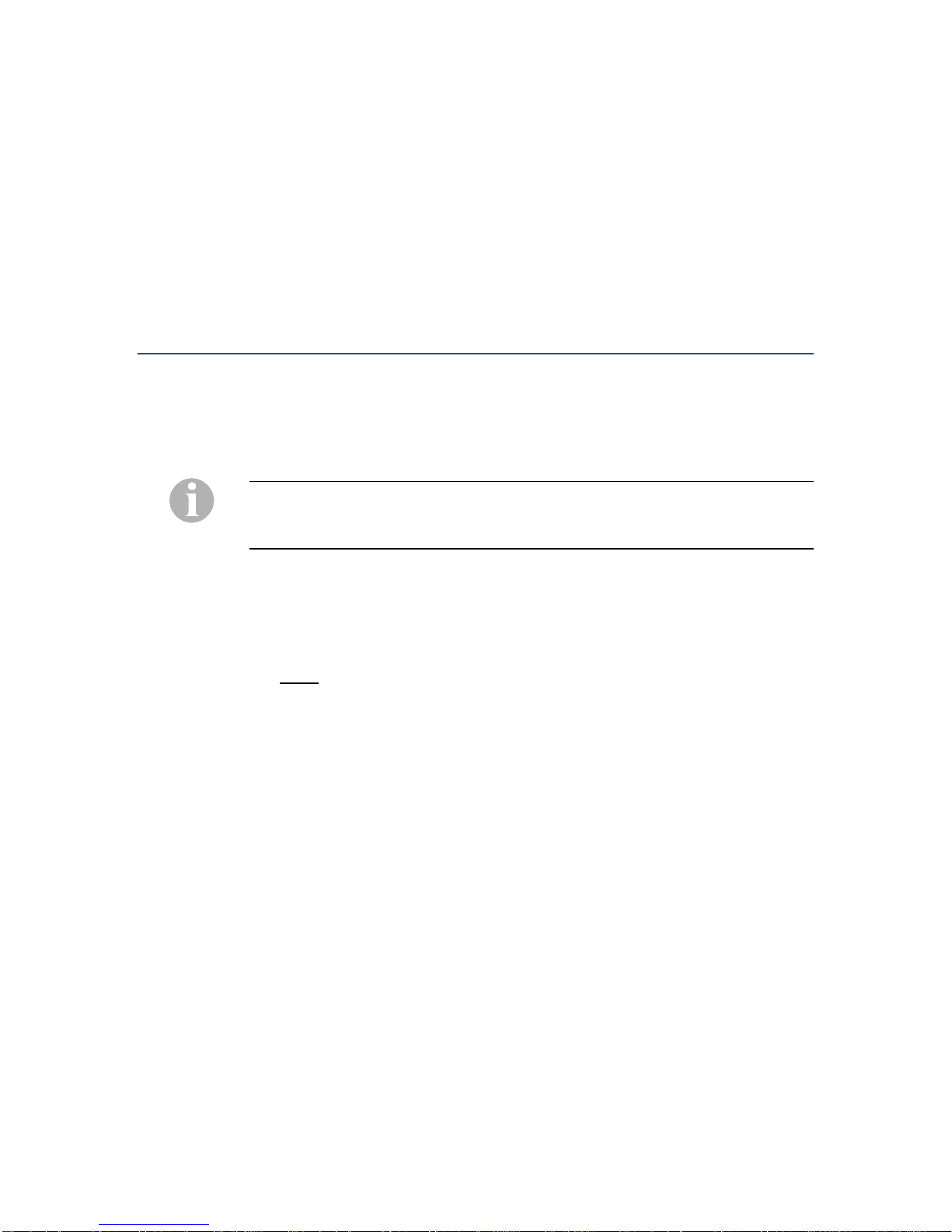
1 INTRODUCTION
Important
Before beginning the installation process ensure that the instructions have
been read and understood completely. Also, ensure that the safety
information about this system has been communicated to appropriate
users and administrators.
Only trained, qualified service personnel should install or maintain this
product. Failure to follow the instructions may result in improperly installed
equipment or risk of electrical shock.
Changes or modifications not expressly approved by Citel Technologies
could void the user’s authority to operate the equipment and will impact
any warranty agreements.
!
What’s in the Box?
Remote Module:
EXTender 1100A Remote Module (1)
Figure 1: Remote Module
Citel System Administration CD (1)
Release Notes – if required (1)
Universal Power Supply A-PUNIV-1 (1)
Power Cord (1)
RJ45ST Patch Cable (1)
RJ45 to DB9 RS232 Cable (1)
RJ45 to RJ11 Digital Phone Cable (1)
RJ11 to RJ11 Telco Line Cable (1)
© Copyright 2008 Citel plc All Rights Reserved

EXTender 1100A Remote Module: Quick Installation Guide 9
2 PLANNING AND PREREQUISITES
You should read the information in this chapter before starting the installation
process as you may need to obtain some information or make changes that
could be difficult when on site.
You Need to Check
1. Which model of PBX is used at the corporate site
2. Which digital telephone at the remote location will be communicating with the
Remote Module port
3. Where the Remote Module will be physically located
4. Access to the power to be supplied to the Remote Module
5. The Remote Module (at the branch office) must be installed properly and the
PSTN line must be operational (a functioning analog line must be connected
to the Remote Module)
6. Power and Wiring
a) The system is designed to operate at 120-240V AC. Do not apply power
to the Remote Module until you are instructed to do so in the installation
procedure
b) Install the Remote Module power supply and cabling away from high RF
noise devices such as computers, fans, fluorescent ballasts and power
supplies
c) Use good wiring practices. Do not run wires over fluorescent lights,
computers, air conditioners, etc., as this can introduce noise.
d) Ensure that the power supply is within 5 feet (1.5 meters) of the Remote
Module
You Need to Know
1. The phone number of the analog line used by the Remote Module.
2. IP Settings (for configuring the units remotely, this is optional):
a) Address – This is the IP address of the Remote Module
b) Subnet Mask – A number used to identify the IP subnet on the LAN
c) Default Router – The address of a device used to reach IP hosts not on
this IP sub-network
3. The unique device name to be used for identifying the Remote Module.
Mike’s Home Office, Sally’s Home Office for example.
4. The model number and release of the PBX in use at the corporate site
5. Corporate guidelines for password configuration and implementation
© Copyright 2008 Citel plc All Rights Reserved

EXTender 1100A Remote Module: Quick Installation Guide 10
6. How to tune the voice parameters to match the network characters by
adjusting the Jitter Delay (described in the System Administrator’s Guide).
7. Any special needs or specific user requirements
You Need to Have
1. All of the items provided in the box with the Remote Module (see the What’s
in the Box? section on Page 7)
2. A copy of the latest software version available for the Remote Module (if
performing a software upgrade)
3. Mounting screws and screwdriver (if wall mounting is required)
4. Access to the supported PBX ports
5. A PC or laptop to connect to the Remote Module with the following
capabilities:
a) A serial port
b) A network port (optional)
c) A terminal emulator such as Windows HyperTerminal for accessing the
Remote Management Console (MC)
d) Microsoft Internet Explorer 5.x or later for configuring the Remote via the
Management Browser (optional configuration method)
6. A Digital telephone with a LCD display. An alternative way to configure the
Remote Module once the protocol is selected.
You Need to Point Out
If a user dials emergency services from the remote location when connected to
the Remote Module and linked to the Switch Module they will reach the
emergency facility that serves the location of the PBX and not the location of the
Remote Module. To ensure that you reach the correct emergency services for
your area use a telephone connected locally.
© Copyright 2008 Citel plc All Rights Reserved
EXTender 1100A Remote Module: Quick Installation Guide 11
3 INSTALLING THE REMOTE MODULE
Instructions for installing the Remote Module and connecting it to the existing
telephone infrastructure are provided in this chapter. Ensure that all of the
prerequisites have been met and that the planning tasks have been completed
prior to beginning the installation.
Before handling or operating the Remote Module make sure that the cover
is correctly secured to the base of the unit – hazardous voltages are
present inside.
Do not attempt to modify the Remote.
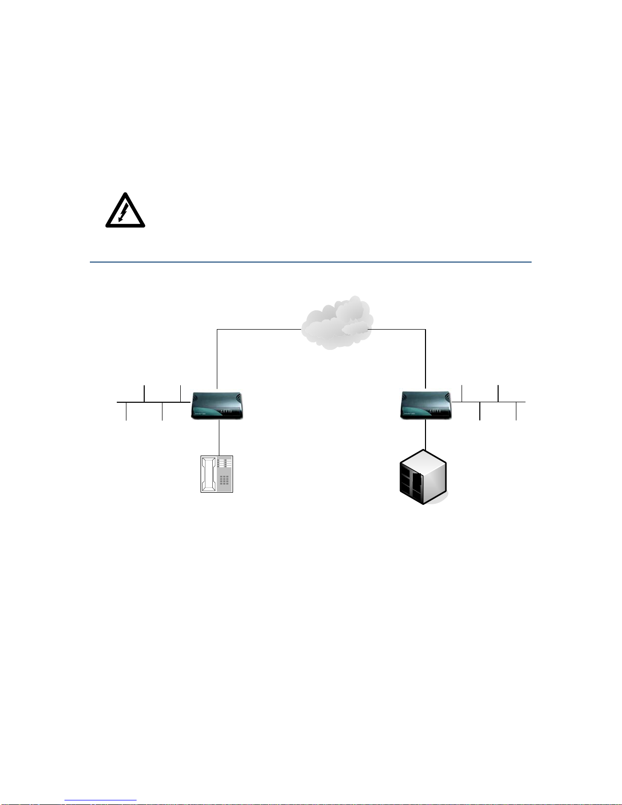
Installation Diagram
PSTN
Analog
Line Analog
Line
EXTender 1100A
(Remote Module) EXTender 1100A
(Switch Module)
Digital
Telephone PBX / KTS /KSU
LAN
(optional)
LAN
(optional)
Figure 2: Installation Diagram
© Copyright 2008 Citel plc All Rights Reserved

EXTender 1100A Remote Module: Quick Installation Guide 12
Physical Installation
Remote Module (left side of Figure 2 – previous page):
1. Place the unit in the destination location. The Remote Module can either be
wall mounted or placed on any desktop.
2. Connect the LAN port to the LAN with an RJ-45 Ethernet cable (optional
configuration method).
3. Prepare to connect the supplied RJ-45 to RJ-11 cable between the port on
the rear of the Remote and a supported telephone set. Do NOT connect the
telephones until the setup wizard has been run.
If the PBX type has not been selected by running the Setup Wizard this can
cause damage to the PBX line cards. Line voltages can vary greatly depending
on the PBX being used.
4. Connect the supplied RJ-45 to DB-9 console cable between the console port
(labeled COMM) and the PC’s serial (COM) port.
5. Connect the supplied RJ-11 to RJ11 cable between the analog line provided
by the PSTN to the Telco port on the rear of the Switch Module.
Do not apply power to the unit until instructed to do so. An improperly
configured Remote can cause damage to the unit or to the telephone sets.
!
Removal Refer to the instructions below when moving or removing the Remote Module:
1. Power down the unit
2. Disconnect the RJ-11 to RJ-11 Telco Phone Cable between the analog line
and the Telco port
3. Disconnect the RJ-45 from the LAN port
4. Disconnect the RJ-45 to RJ-11 cable between the port on the Remote
Module and the telephone
5. Disconnect the RJ-45 to DB-9 console cable between the console port and
the PC’s serial (COM) port
6. Remove the unit from the desktop or wall (if wall mounted)
© Copyright 2008 Citel plc All Rights Reserved

EXTender 1100A Remote Module: Quick Installation Guide 13
Setting up the COM Port
The Remote Module can be configured through the serial port when using a
terminal emulator such as Windows HyperTerminal. The following are the steps
necessary to access the Remote Module’s Management Console.
1. Start a HyperTerminal session. On a default installation of Windows XP, for
example, at the Start menu select Programs, Accessories,
Communications and finally HyperTerminal.
2. Enter a name for the new connection in the Name box – Remote, for
example
3. Select the COM port you are using from the options in the Connect drop-
down list
4. Check the configuration of the communications port and make sure that the
settings are as follows:
Bits per second 9600
Data bits 8
Parity None
Stop bits 1
Flow Control None
5. Plug the power supply in to the Remote Module and then into the AC wall
outlet. Allow the unit to complete the bootup sequence.
6. Wait a few seconds and the “Press ‘Enter’ to start the shell…” prompt is
displayed.
7. Press Enter. A password prompt is displayed if a password is set (there is no
default password).
If the Remote Module is running but you do not see these prompts the serial
connection between your computer and the unit may be at fault. You must
correct this problem before you can use the HyperTerminal connection
successfully.
8. Type the unit’s password, if one was set, and press Enter. The Management
Console welcome screen is displayed
9. To ensure that you can see all the information displayed you must set the
screen size to 24 lines by 80 columns. The screen size is correctly set when
the Welcome screen is displayed with the ‘#’ border.
© Copyright 2008 Citel plc All Rights Reserved
EXTender 1100A Remote Module: Quick Installation Guide 14
Power up LED Sequence
During power up of the Remote Module the following LED flashing sequences
are presented:
Test LED Status
DRAM Test Status LED 1 – Green Flicker
Status LED 2 – Off
PSTN LED – Off
Self Test Status LED 1 – Solid Green
Status LED 2 – Off
PSTN LED – Off
ROM Countdown Status LED 1 – Solid Green
Status LED 2 – Off
PSTN LED – Green Flicker
Loading Image Status LED 1 – Green Flashing
Status LED 2 – Off
PSTN LED – Solid Green
Loading Image Successful Status LED 1 – Solid Green
Status LED 2 – Off
PSTN LED – Solid Green
Table 2: Power up LED Sequence
© Copyright 2008 Citel plc All Rights Reserved
EXTender 1100A Remote Module: Quick Installation Guide 15
4 CONFIGURING THE REMOTE
MODULE
This chapter describes the necessary steps to configure the Remote Module
using the Management Console (MC). The unit is programmed at the factory with
default settings to provide the basic parameters to accommodate most network
environments.
The Setup Wizard
After the unit has been powered up a series of self diagnostics tests will be
performed. When complete, the following prompt will be presented:
Press ‘Enter’ to start the shell...
If power is supplied to the Remote Module prior to running Windows
HyperTerminal (or equivalent communications software) this message will not be
displayed.
Pressing Enter will result in the administrator being prompted to run the Setup
Wizard. The Setup Wizard will ask the administrator a series of questions to
assist with the configuration process. It is highly recommended that the Setup
Wizard be run at the start of any new installation. The administrator can also run
the Setup Wizard at any time to change the configuration parameters:
Path: Remote->Utilities->Setup Wizard
Follow the Setup Wizard to configure the Minimum Required parameters:
1. A unique name for the Remote (i.e. Mike’s Home Office)
2. Region Code – the region is set automatically depending on the country code
selected
3. Select the appropriate PBX type
4. Enable or disable the Leased Line Mode depending on the analog line type
being used
5. Enter the Office Dial Number – this is the phone number of the analog line
that is connected to the Switch Module (only required if Leased Line is
disabled).
Additional Configuration Parameters:
6. Manually enter the Connect Rate (default is Auto)
7. Enable or disable Pulse Dialing depending on the analog line service
8. Enable or disable Dialback – the Dialback feature is used for the Switch to
automatically call back the remote during a connection attempt
9. Enter a User ID (if required) – the User ID is used to “map” the port to a
specific port on the Switch Module. Typically used for connecting to one of
© Copyright 2008 Citel plc All Rights Reserved

EXTender 1100A Remote Module: Quick Installation Guide 16
Citel’s multi-user PBXgateways (refer the System Administrator’s Guide for
more details).
10. IP Parameters (or DHCP):
a) IP Address
b) Subnet Mask
c) Default Router
11. When complete the administrator is prompted to save the changes and
reboot.
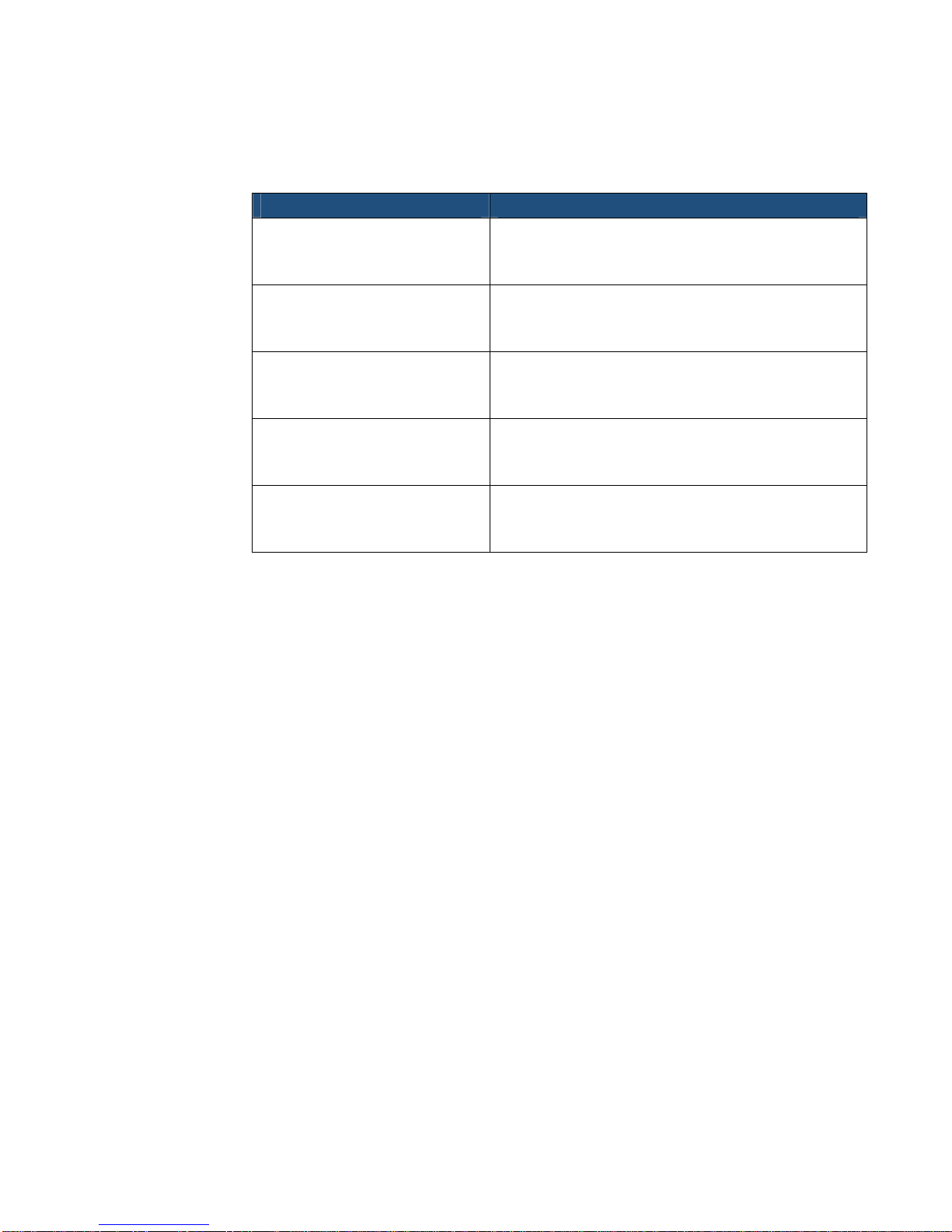
Navigating the Management Console
After the Setup Wizard has been run successfully the main Management
Console (MC) screen can be accessed. The MC uses command keys and cursor
keys to navigate through the sub-menus:
Key Description
Cancel, leaving values at their previous settings.
Accepts the change you have entered or exits the
current menu option. Administrator will also be
prompted to save configuration changes if required.
or
Access the currently selected menu item.
or Go to an item in a menu. You can also select a menu
item by typing the first character in its name.
or + A Help screen. This help screen is for the UI itself and
not the features listed in the UI.
or + R Refreshes the current screen.
Table 3: Navigating the Management Console
Remote Module Telephone Management Interface
The Telephone Management Interface (TMI) can also be used for setting the
configuration parameters for the 1100A Remote Module using a digital telephone
with a display. For ease of use it is recommended that a telephone with a two-
line display be utilized for any telephone MI programming.
You must set the PBX type, in the Console Setup Wizard, before being able to
use the Remote Module TMI.
© Copyright 2008 Citel plc All Rights Reserved

EXTender 1100A Remote Module: Quick Installation Guide 17
Accessing the Phone Telephone Management Interface
Press the “Hold” key on the telephone four times. This can be done while offline
or online (Extended). When Online you only access the Disconnect menu, you
must again press ‘Hold” key on the telephone four times to access the online
menu.
Menu Legend
Navigating through the telephone interface menus is done using the keypad on
the telephone or soft menu keys below the LCD display (if the telephone is
equipped with Soft menu keys). The menu legend shows each applicable
numeric key and the screen or command to which it corresponds in the interface.
Prv/Prev = 1(left most soft key) on the telephone keypad: Previous
Screen
Ok = 2(middle soft key) on the telephone keypad: Accept
changes/enter
menu
Nxt/Next =3 (right most soft key) on the telephone keypad: Next Screen
© Copyright 2008 Citel plc All Rights Reserved

EXTender 1100A Remote Module: Quick Installation Guide 18
Essential Configuration
Essential Setup Wizard Configuration
You must run the Setup Wizard to set the Region Code and PBX type, both are
part of the Minimum Required configuration.
Path: Remote->Utilities->Setup_Wizard
1. Setting the Region Code is done only through the Setup Wizard. When you
select the Country code for you unit the Region Code will be determined from
what country is configured.
2. Setting the PBX Type is done only through the Setup Wizard. You are
prompted one at a time of supported PBX types. Simply select the PBX type
you want your Switch Module to be configured for.
Essential Connect Parameters - Modem Settings
There is only one essential Modem Setting configuration for the Remote side and
that is the Telco type which is the Leased Line setting, using the default setting
for the remaining Modem Settings should be satisfactory. Modem Settings can
be configured using the Setup wizard or using the MC.
Path: Remote->Utilities->Setup_Wizard
Path: Remote->Configuration->Connect
You can also configure Modem setting using the TMI
TMI Path: (Remote Only)->Set Config->Modem Menu
3. Setting the Modem Settings Telco Type – Telco Type determines how the
modem connection will be initiated. If Leased Line is disabled then the
connection is dial-up (will use dial numbers) if enabled then will use a tone
handshaking mechanism to trigger the modem connection.
a) Leased Line – An analog leased line is a telephone line type offered by
the telephone service provide (CO) and would be a dedicated line
between the Switch and Remote Module (not a “dialup” connection).
Only ‘wet’ leased lines are supported. A standard analog line (Leased
Line disabled) is the default setting.
Essential Connect Parameters – Dial Numbers
The Dial Numbers are used to connect to the Switch Module from the Remote
Module over the PSTN via the internal modem. They are only required if Leased
Line mode is disabled (in dial-up mode). They can be configured using either the
Setup Wizard or the Configuration menu item.
Path: Remote->Utilities->Setup_Wizard
Path: Remote->Configuration->Connect->Dial_Numbers
You can also configure the Dial Numbers using the TMI
TMI Path: (Remote Only)->Set Config->Connect Menu->Office Number
© Copyright 2008 Citel plc All Rights Reserved

EXTender 1100A Remote Module: Quick Installation Guide 19
4. Setting the Dial Numbers – Dial Numbers are used to connect the Switch
Module from the Remote Module:
a) Office Number – This is the phone number of the telephone line
connected to the Switch Module. Is always required for Dial up
connections.
b) Remote Number – This is the phone number of the telephone line
connected to the Remote Module. This number will be transmitted to the
Switch Module for use with the Dialback feature (and is also used to
identify the Remote Module connected to the Switch module). The
remote Number is only required for Dialback operation. Refer to the
Advanced Configuration for more details.
Recommended Connect Parameters – User ID
There is one more Recommend connect parameter to configure. The User ID is
required for all 1100A connections. The default Remote User ID is not
configured so on each connection the user would be prompted to enter the
desired User ID. If the User ID is configured then the remote User will not be
prompted each connection. The User ID can be configured using the Setup
Wizard or the MC.
Path: Remote->Utilities->Setup_Wizard
Path: Remote->Configuration->Port
You can also configure some Connect Parameter settings using the TMI
TMI Path: (Remote Only)->Set Config->Connect Menu-> User ID
5. Setting the User ID. A User ID “maps” a specific port on the Remote Module
to a specific port on the Switch Module. When connecting to the 1100A
Switch you require a User ID. The default ID is 1 (representing the port
number). This feature is also typically used when connecting to one of Citel’s
multi-user devices such as a PBXgateway. If this remote is connecting to a
multi-user device refer to the System Administrator’s Guide of the
PBXgateway for more information.
THE ESSENTIAL CONFIGURATION PARAMETERS FOR THE
REMOTE MODULE ARE NOW COMPLETE.FOR ADVANCED
CONFIGURATION PARAMETERS REFER TO THE LIST ON
Advanced Configuration – Quick Reference OR THE
SYSTEM ADMINISTRATOR’S GUIDE FOR FULL DETAILS.
PLEASE TEST THE CURRENT CONFIGURATION BY MAKING A
FEW “TEST”PHONE CALLS PRIOR TO GOING ON TO THE
ADVANCED CONFIGURATION SECTION.
© Copyright 2008 Citel plc All Rights Reserved
EXTender 1100A Remote Module: Quick Installation Guide 20
Testing the Installation
If the units are installed properly, but you still cannot connect the remote
telephone to the Switch Module, you should test the Dial Numbers.
1. Connect the Remote Module’s telephone line to an analog phone
2. Connect the Switch Module’s telephone line to an analog phone also
3. Call the Switch Module’s telephone number from the Remote Module’s
location. Confirm that the phone rings and that the voice path is established.
4. Make the necessary changes to the Dialback numbers if required. Reconnect
the analog lines to the Switch and Remote Modules and attempt to connect.
If problems persist refer to the Trouble Shooting section in the System
Administrator’s Guide. There are optional configuration parameters also available
to the administrator.
Optional Configuration Method
There is an optional configuration method also available to the administrator.
Enabling the Management Browser
The Remote Module can also be configured via an HTML interface. The Web
Server feature must first be enabled in order to administer the units with this
method.
1. Web Server – In order to configure the units using the Management Browser
(MB) the Web Server must be set to “Enabled.”
Path: Remote->Configuration->IP->LAN
2. There must also be a valid IP Address entered for the Remote.
Path: Remote->Configuration->IP->LAN->Address
Additional Management Browser parameters can also be configured either prior
to launching the MB or any time after.
3. Web Timeout – This parameter determines the amount of time a
Management Browser screen can be left idle (no programming activity)
before the session is terminated.
Path: Remote->Configuration->IP
4. Web Refresh LED – The Port Status LEDs update every 10 seconds. If the
frequent updates are found to be a hindrance during administration of the
Switch Module the LED refreshing can be disabled.
Path: Remote->Configuration->IP
© Copyright 2008 Citel plc All Rights Reserved
Other manuals for EXTender 1100
2
This manual suits for next models
1
Table of contents
Other Citel Switch manuals


Popular Switch manuals by other brands

3Com
3Com OfficeConnect 140 user guide

Moxa Technologies
Moxa Technologies ICS-G7526A Series Quick installation guide

ATEN
ATEN CS1708i Specifications

Siemens
Siemens 3VL9800-3HA0 operating instructions

Enabling Devices
Enabling Devices Gooshey Switch 636 manual

Lantronix
Lantronix SISTP1040-382B-LRT install guide


