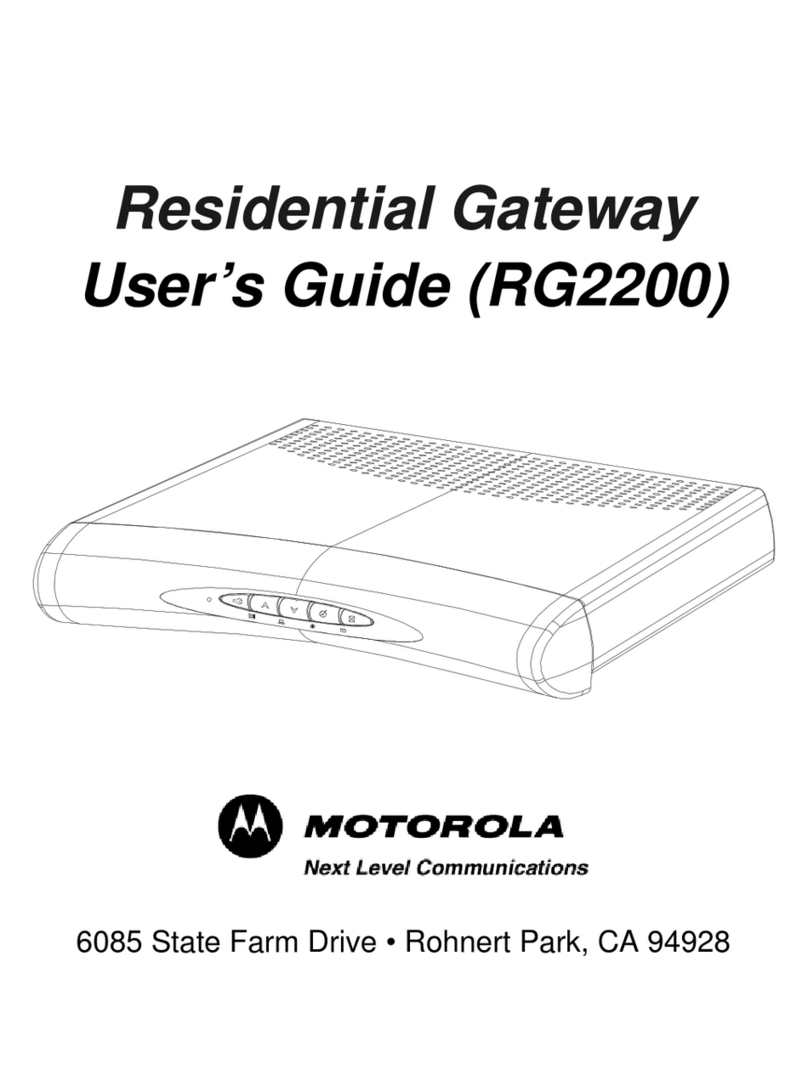
CITELlink SIP Handset Gateway User manual

©CITEL Technologies Ltd 2004
SIP Handset Gateway
Installation& Configuration
Guide
IP Centrex/Softswitch Compatibility Asterisk, Broadsoft, Sylantro
Telephone Compatibility Nortel–Meridian 1, Norstar
Document Number 1764
Version 1.00

2
1764 Version1.00 ©CITEL Technologies Ltd 2004
!
Copyright information
CITEL and CITELlink are trademarks of CITEL Technologies Ltd.
Broadsoft and Sylantroare registered trademarks of Broadsoft Inc. andSylantro Systems Corporation
respectively.Asterisk is The Open Source PBX, details available fromwww.asterisk.org. Other names
may be trademarks owned by third parties.
© 2004 CITEL Technologies Ltd. Proprietary. No part of these materials may be disseminated, copied
or reproduced without prior written consent of CITEL Technologies Ltd. All rights reserved.
The contents of these materials are for information purposes only. CITEL Technologies Ltd makes no
representations or warranties whether express or implied as to the accuracy or completeness of these
materials and shall not be liable for any loss or damage suffered or incurred as a result of reliance upon
or use of them.
CITEL Technologies Ltd reserves the right, without prior notice, to change the equipment, designs or
documentation referred to herein as it considers necessary.
Conventions
Table 1lists conventions used throughout this guide.
Table 1–Notice Icons
Icon Notice Description
Warning
Information that alerts the reader to a potential
danger of physical harm to personnel.
Caution
Information that alerts the reader to potential loss of
data or damage to an application, system, or device.
Information
note
Information that describes important features or
instructions.
Electrostatic
Sensitive
Device
Information to alert the reader to the presence of
devices sensitive to electrostatic discharges.

3
1764 Version1.00 ©CITEL Technologies Ltd 2004
CONTENTS
Conventions .................................................................................................... 2
1ABOUTTHISGUIDE 6
Important ........................................................................................................ 6
2ABOUT THE PRODUCT 7
Product description.......................................................................................... 7
3BOX CONTENTS 9
In-box items .................................................................................................... 9
4PLANNING AND PRE-REQUISITES 11
Installer..........................................................................................................11
Phone Users ..................................................................................................11
Hardware.......................................................................................................11
Software........................................................................................................12
Limitations .....................................................................................................12
5INSTALLATION AND CONFIGURATION 13
Gateway Installation .......................................................................................14
Gateway Removal ..........................................................................................14
Gateway Configuration...................................................................................14
6SOFTWARE UPGRADES 26
Overview .......................................................................................................26
7USER INFORMATION 27
Telephone Functionality..................................................................................27
Country-Specific Safety and Operating Information ...........................................27
8TROUBLESHOOTING 28
Checklist........................................................................................................28
Dealing with damaged or faulty items...............................................................28
APPENDIX A –TECHNICAL SPECIFICATION 29
Front panel.....................................................................................................30
RJ21x Wiring..................................................................................................33
SIP Gateway wiring chart for legacy Telephones ..............................................34

4
1764 Version1.00 ©CITEL Technologies Ltd 2004
APPENDIX B –SAFETY INFORMATION 36
Important Safety Instructions ...........................................................................36
Scope............................................................................................................36
General..........................................................................................................36
Installation of Telecommunications Wiring........................................................37
Symbols.........................................................................................................37
Installation Summary ......................................................................................38
Fuse and Component Replacement.................................................................38
System Grounding (Earthing) ..........................................................................39
General Grounding .........................................................................................39
Grounding Conductor.....................................................................................39
Protective Grounding Conductor......................................................................39
Regulatory Notices .........................................................................................40
Notice to US Customers..................................................................................40
Notice to Canadian Customers ........................................................................41
Notice to European Customers........................................................................42
APPENDIX C –SERIAL CONNECTION TOTHE GATEWAY 44
Serial Connection...........................................................................................44
APPENDIX D –EXAMPLE CONFIGURATION SESSION USING
HYPERTERMINAL 45
HyperTerminal Session Output........................................................................45
APPENDIX E –GLOSSARY 47
Terms and Acronyms......................................................................................47
APPENDIX F –CONTACTING ABP TECHNOLOGY49

5
1764 Version1.00 ©CITEL Technologies Ltd 2004

6
1764 Version1.00 ©CITEL Technologies Ltd 2004
!
1ABOUT THIS GUIDE
This guide provides instructions on how to set up the CITELlink SIP Handset Gateway, and is
intended for CITEL Authorized Partners only.
These instructions provide basic installation information, necessary for the proper and safe
functioning of this equipment. Persons installing or maintaining this product must read all of
the safety instructions and the parts of system grounding which are applicable to the system
being maintained. Only trained, qualified service personnel shall install or maintain this
product.
Important
This guide and warranty and liability details are published in the downloads area at
www.citel.com -note you need the CITEL Choice Partner password to access the
information. Any questions regarding the use of this guide may be directed to
If release notes are provided for the product and the information therein differs from the
information in this guide, the release notes override this guide.
Before attempting installation, ensure you have read and comply withall instructions
including the Safety Information in this guide. Also ensure you communicate the
same information to the users and administrators of the telephone system in which a
CITELlink SIP Handset Gateway is operating.
Failure to follow all instructions may result in improper equipment operation and/or
risk of electrical shock.
Changes or modifications not expressly approved by CITEL could void the user's authority to
operate the equipment

7
1764 Version1.00 ©CITEL Technologies Ltd 2004
2ABOUT THE PRODUCT
Product description
The CITELlink SIP Handset Gateway (the Gateway) enables users of legacy Northern
Telecom (Nortel) digital telephones to access an IP Centrex telephone system.The Gateway
acts as an interface between the legacy Nortel telephones and the SIP proxy servers. When
supported telephones are configured on the Gateway, phone features—including the
displays, softkeys, and supported hardkeys—function like they do on SIP telephones.
Legacy telephone models supported are listed below. Refer to Telephone Button Mapping
guides at www.citel.com for details of specific telephone model functionality.
Supported Telephones
Table 2 –Supported Telephones
Nortel Norstar
M7100 T7100
M7208 and M7208N T7208
M7310 and M7310N T7316
M7324 and M7324N T7406 (digital cordless)
Nortel Meridian 1
M2006 M3901
M2008 M3902
M2616 M3903
M3110 M3904
M3310
M3820
The Gateway is a rack-mountable unit. Each Gateway supports up to 24 legacy telephones
and is connected to the legacy telephones using the existing telephone wiring, punchdown
blocks and connectors. No additional telephone power is required. The legacy telephones are
line powered from the SIP Gateway through an integral power source.
The maximum loop length is 1600ft/500m. THIS MUST NOT BE EXCEEDED.

8
1764 Version1.00 ©CITEL Technologies Ltd 2004
Figure 1–Example installation of the CITELlink SIP Gateway

9
1764 Version1.00 ©CITEL Technologies Ltd 2004
3BOX CONTENTS
In-box items
The Gateway is supplied in one box containing four items:
1CITELlink SIP Gateway unit (with warranty information).
Figure 2 –CITELlink SIP Gateway unit
2Rack mounting Brackets and fasteners.
Figure 3 –Rack Mounting Brackets and Fasteners

10
1764 Version1.00 ©CITEL Technologies Ltd 2004
3Power supply lead: All boxes contain a US power supply lead as standard. For
other countries an alternative country-specific power supply lead is also provided
as a separate item (without charge). Refer to Appendix A for specification.
Figure 4 –Power Supply Lead
4Overview document for the product.

11
1764 Version1.00 ©CITEL Technologies Ltd 2004
4PLANNING AND PRE-REQUISITES
This chapter provides a checklist-format note of planning considerations prior to installation.
Installer
1The Gateway must be installed by a certified CITEL partner, contact
Phone Users
1Ensure all the legacy telephones aresupported on the Gateway
2Ensure you have 24 or fewer legacy telephones per Gateway
3Ensure each legacy telephone is relabeled for the new IP Centrex functions
4Ensure legacy telephone users have been trained on the new IP Centrex
telephone functionality
Hardware
Ensure you have the following minimum hardware to install and operate the Gateway:
1All in-box items for the Gateway
2Connection via LAN or WAN to a supported IP Centrex System, using CAT5
straight-through cable with RJ-45 connectors
3A.C. power source within 5 feet / 1.5 m (see Appendix A for other environmental
specifications)
4Correct power cord for the country of installation (see Appendix A for
specifications)
5RJ21x 50-way extension line with 25-pair/50-way Amphenol-type connectors to
connect between the 50-way male connector on the gateway, and a punchdown
block (may reuse existing wiring)
6Punchdown block and telephone cables (may reuse existing wiring)
7Ensure the station wiring for each telephone is within the maximum loop length
(see page 7)
8Ensure the station wiring for each legacy telephone is appropriate quality for
digital telephone operation (Cat 3 minimum)
9RS232 straight-through DTE 9-pin serial cable

12
1764 Version1.00 ©CITEL Technologies Ltd 2004
Software
Appropriate IP Centrex system software must be installed and functioning, to install and
operate the Gateway:
1An allocated extension range from your Service Provider.
Limitations
CITEL publishes Release Notes for the CITELlink SIP Gateway at www.citel.com. Refer to
those Notes for specific information on product status. Get details of the SIP Feature Set from
your ISP.

13
1764 Version1.00 ©CITEL Technologies Ltd 2004
5INSTALLATION AND CONFIGURATION
This chapter describes installation and configuration of the CITELlink SIP Gateway. Please
read through the whole of this document before installing and configuring the SIP Gateway.
The following steps are required to register the legacy telephones and install and configure
the Gateway:
1Install the Gateway
2Configure the Gateway to register the legacy telephones
3Test telephone operation
Before handling or operating the CITELlink SIP Gateway, always ensure the cover is
correctly secured to the base of the unit -hazardous voltages are present inside
Do not attempt to modify the Product

14
1764 Version1.00 ©CITEL Technologies Ltd 2004
Gateway Installation
1Place the unit in the destination location (conforming to environmental
requirements in Appendix A). If mounting it in a 19-inch rack, use the mounting
brackets supplied. These fasten to the sides of the rack
2Connect a CAT 5 cable between the Gateway ethernet port and a layer 2 switch
on the LAN or WAN where it is to be installed
3Apply power to the Gateway, and allow it time to complete the boot sequence
(check LED information on page 30 for details).
4Connect the RJ21x 50-way extension line connector between the Gateway front
panel and the punchdown block
The legacytelephones will then terminate on this block. For wiring details, see page 34
GatewayRemoval
To remove the CITELlink SIP Handset Gateway, disconnect the RJ21x 50-way extension line
and remove power and LAN connections to the unit. You may then remove the SIP Gateway.
Gateway Configuration
The CITELlink SIP Gateway requires configuration for:
•SIP Gateway IP Addressing
Specify relevant IP addresses:
-SIP server IP addresses, including TFTP and other servers if required;
-2 IP addresses for the CITELlink SIP Gateway (one for ports 1-12, a second for
ports 13-24). Generally static IP addresses are recommended, as these IP
addresses are also used to access the CITELlink web interface. If you do not use
static addresses, consider how you will make the CITELlink web interface available
when needed (e.g. a DNS to DHCP lookup might be needed)
•Configuration ofthe line (AOR) on each SIP Gateway port
•Configuration ofbutton mappings and line appearances for eachtelephone
If you do not configure the CITEllink SIP Handset Gateway with IP and line information, the
legacy telephoneswill not operate.

15
1764 Version1.00 ©CITEL Technologies Ltd 2004
CITELlink SIP Gateway IP Addressing
When you first install the Gateway on a new network, you must set the following details.
Setting these details for the first time is achieved using a serial connection as described
below. Subsequent configuration changes may be made via the web interface as on page 18.
Figure 6 –Gateway Configuration Details
Value Description
Interface 1 (Ports 1-12) IP Address
If DHCP is enabled, this setting is not required
If DHCP is not enabled, you must assign a static
IP address for Gateway ports 1 to 12
Whether or not DHCP is enabled, the DHCP IP
address used by Interface 1 is used for web
browser access to the CITELlink Web
Configuration for these ports
Interface 2 (Ports 13-24) IP Address
If DHCP is enabled this setting is not required
If DHCP is not enabled, you must assign a static
IP address for Gateway ports 13 to 24
Whether or not DHCP is enabled, the DHCP IP
address used by Interface 2 is used for web
browser access to the CITELlink Web
Configuration for these ports
DHCP Enabled?
Default is TRUE
If FALSE, static IP addresses must be entered
for Interface 1 and Interface 2 (above)
The IP addresses assigned to Interface 1 and
Interface 2 are also used to access the
CITELlink web interface. If you enable DHCP,
consider how you will make the CITELlink web
interface available for browser access (e.g. a
DNS to DHCP lookup might be needed)
Net Mask
Specify the appropriate IP Net Mask for your
network, e.g. 255.255.255.0
Config Address
Specify the appropriate IP address for the
Configuration Server for your network
The Configuration Server hosts a TFTP Server
which serves up configuration files to the
Gateway, at boot time

16
1764 Version1.00 ©CITEL Technologies Ltd 2004
!
App FileName
Specify the appropriate filename for the
CITELlink software e.g. tig_sip_<phone>.bin
The Gateway checks for updates in the root
directory of the TFTP Server. If a file with the
specified name is present, and is different to the
current software load, the Gateway will load the
file when the next Update is triggered. Updates
are triggered from AutoUpdate at boot time, or
via a HyperTerminal menu command (also see
Auto Update)
Auto Update
Default is FALSE
If TRUE, the Gateway will check for updates at
the next boot (also see App FileName)
Optionally, you may also provide the following details:
Default Route
Specify the appropriate IP address for the
default router for your network
Not a mandatory setting.
DNS Server
Specify the appropriate IP address for the DNS
Server for your network
Not a mandatory setting.
Syslog Server
Specify the appropriate IP address for the
Syslog server
If the Gateway is configured to output
diagnostics, the Syslog Server specifies the IP
address to which the output is directed. This
feature is intended for use when advised by
CITEL Technical Support
Not a mandatory setting.
Clear All User Configuration
Default is FALSE
If TRUE, all user configuration settings (except
basic IP details) are removed
Do NOT use this option unless
you intend to delete all port, line
and handset configurations
(including passwords)

17
1764 Version1.00 ©CITEL Technologies Ltd 2004
!
Initial IP Configuration
The Gateway is shipped with addresses unset, and DHCP enabled as the default
configuration. Initial configuration is achieved using a serial cable and HyperTerminal
session, working through a configuration menu as described below. Details of how to connect
a HyperTerminal session between a PC and the Gateway are provided in Appendix C.
Output from an example configuration session is provided in Appendix D.
The HyperTerminal connection to the Gateway offers access to a full diagnostic and
configuration command structure. Only use the commands listed and described in this
document, unless otherwise instructed by CITEL.
Caution –incorrect command use may take the CITELlink SIP Gateway out of service.
Once you have established a HyperTerminal session, boot the Gateway by connecting the
power supply. You will see the boot sequence start to output data to the HyperTerminal
session. Wait until the boot is completed (check the LEDs for normal operation, as described
in Table 6 .
At the prompt DCP [support]$, enter the following commands to configure the IP details:
setcfg answer the questions as they appear, entering appropriate IP addresses for the
Gateway, the net mask, and the configuration address. Ensure appropriate
values are set for all other attributes. Also ensure your final selection is
INFO : WriteToFlash?: TRUE
.. supply the password (default is citel –you should change this as soon as
possible), then you get a new prompt, DCP [/]$
boot you get a new prompt, DCP [boot]$
reboot this causes the Gateway to reboot, using the new configuration settings

18
1764 Version1.00 ©CITEL Technologies Ltd 2004
Configuration via the Web Browser
Once the initial configuration is completed and the Gateway has rebooted, all future
configuration may be achieved via the CITELlink SIP Gateway Web Browser interface
(Gateway Portal). Navigate to the relevant screen (use the appropriate IP address for the
Gateway), and enter the configuration details as described below.
Note that configuration changes require a reset to either the Gateway or the Telephone
(depending on what configuration change has been made).
Figure 7 –Gateway Portal
Use the System Information option to list the current Gateway configuration.

19
1764 Version1.00 ©CITEL Technologies Ltd 2004
Figure 8 –Gateway Portal –System Information
Use the Configure option to change configuration details. Other options are available to
Configure Passwords, Set Date and Time, and access the Log.
If you use the Configure option the following dialog box appears.

20
1764 Version1.00 ©CITEL Technologies Ltd 2004
Figure 9 –Gateway Portal –IP Configuration
Enter the appropriate values for your own network configuration and click on Submit, then
Reset. This causes the Gateway to reboot, using the new configuration details.
Table of contents

