CiTO Power CPI-500 Series User manual

USER MANUAL
CiTO Power-INVERTERS Series
CPI-500 / CPI-1000

General Precautions
1. Before using CPI-500 / CPI-1000, read all instructions and cautionary
markings on : (1)CPI-500M / 1000M (2) The batteries (3) This manual
2. CAUTION --To reduce risk of injury, charge only lead-acid type
rechargeable batteries. Other types of batteries may cause damage and
injury.
3. Do not expose Inverter to rain, snow or liquids of any type. Inverter is
designed for indoor.
4. Do not disassemble the Inverter. Take it to a qualified service center when
service or repair is required.
5. WARNING: Provide ventilation to outdoors from the battery compartment.
The battery enclosure should be designed to prevent accumulation and
concentration of hydrogen gas at the top of the compartment.
6. NEVER charge a frozen battery.
7. Input/output AC wiring must be no less than 18 AWG gauge copper wire
and rated for 75oC or higher. Battery cables must be rated for 75oC or
higher and should be no less than 10AWG gauge. The inner diameter of
the copper ring terminal which is used to connect battery cables to
Inverter DC terminals should be no less than 6mm.
8. Be extra cautious when working with metal tools around batteries.
Short-circuiting the batteries could cause an explosion.
9. For battery installation and maintenance: read the battery manufacturer’s
installation and maintenance instructions prior to operating.
10. CiTO Power Inverters can be used with fan, bulb, TV, heater, iron, etc.
Consult local technicians for more advices.
Personnel Precautions
1. Have plenty of fresh water and soap nearby in case battery acid contacts
skin, clothing, or eyes.
2. Avoid touching eyes while working near batteries.
3. NEVER smoke or allow a spark or flame in vicinity of a battery.
4. Remove personal metal items such as rings, bracelets, necklaces, and
watches when working with batteries. Batteries can produce a short-circuit
current high enough to make metal melt, and could cause severe burns.

5. If a remote or automatic generator start system is used, disable the
automatic starting circuit or disconnect the generator to prevent accident
during servicing.
Introduction
CiTO Power Inverters CPI-500 / 1000 is a DC-to-AC inverter with auto
line-to-battery transfer and integrated charging system, serving as an
extended run UPS, a standalone power source or an automotive inverter.
CPI-500 / 1000 supplies power from AC power and DC source. When AC
cable is connected to a wall socket, utility power goes to connected
equipment(s) and/or charges the battery set via charging system. In UPS
mode, Inverter automatically converts battery energy into AC power for
backing up the connected devices.
Features:
zAutomatic line-to-battery switchover
zSelectable Input voltage ranges
zHigh efficient DC-to-AC conversion, minimizing energy loss
zRack Tower design for flexible placement
zBuilt-in enhanced charger
zIntelligent 2-stage charger control for efficient charging and preventing
overcharge
zProvides overload protection
zAuto restart whileAC recovery
zMulti-function LED indications and buzzer alarms

Operation
Front Panel Controls and LED Indicators
Shown below are the controls and indicator lights on the front of CPI-500 /
1000
Figure 1 Front Panel of CPI-500 / 1000
Power
On/Off
Power on/off button is shown as above. Once Inverter has been properly
installed and batteries are connected, press this button and Inverter will turn
on automatically, and works in mains mode or inverter mode according to
input AC source’s status. When press this button again, Inverter will turn off
automatically.
Mains Mode LED
The green LED will blink or light steadily when power mains is normal.
Note: The green LED blinks every 2 seconds to indicate that battery capacity
is not full enough and battery is being charged by high rate.
Inverter Mode LED
The Yellow LED will light when power mains is abnormal. And unit will work
in inverter mode.
Fault LED
The red LED will light when fault occurs.

Back Panel Description
Shown below are the components on the back of CPI-500 / 1000.
Figure 2 Back Panel
1. DC Input Connector (Battery Terminal)
2. Input Breaker
3. AC Input Connector (Three-station Terminal Block)
4. Output Receptacle(s)
5. Input Voltage Range Selector : (Input voltage range is defined in
specification chapter, and output voltage is the same as input voltage in
mains mode)
A. Select ‘Narrow’ setting for general electrical appliances,
B. To save energy, ‘Wide’ setting could be selected only when using
some special load, such as daylight lamp, fan etc.

Battery Connection
Step 1- Pinch the bottom of DC input cover and Open it. See Figure 4.
Step 2- Following battery polarity guide located near battery terminal. Place
the battery cable ring terminal over Inverter’s battery terminal.
Tighten the M5 nut. Do not place anything between the flat part of
battery terminal and the battery cable ring terminal, or overheating
may occur.
Figure 4 Battery Cable Connections to CPI-500 / 1000
Caution! DO NOT place
anything between battery cable
ring terminals and battery
terminals. The terminal stud is
not designed to carry current.
Apply Anti-oxidant paste to
terminals after terminals have
been securely connected.
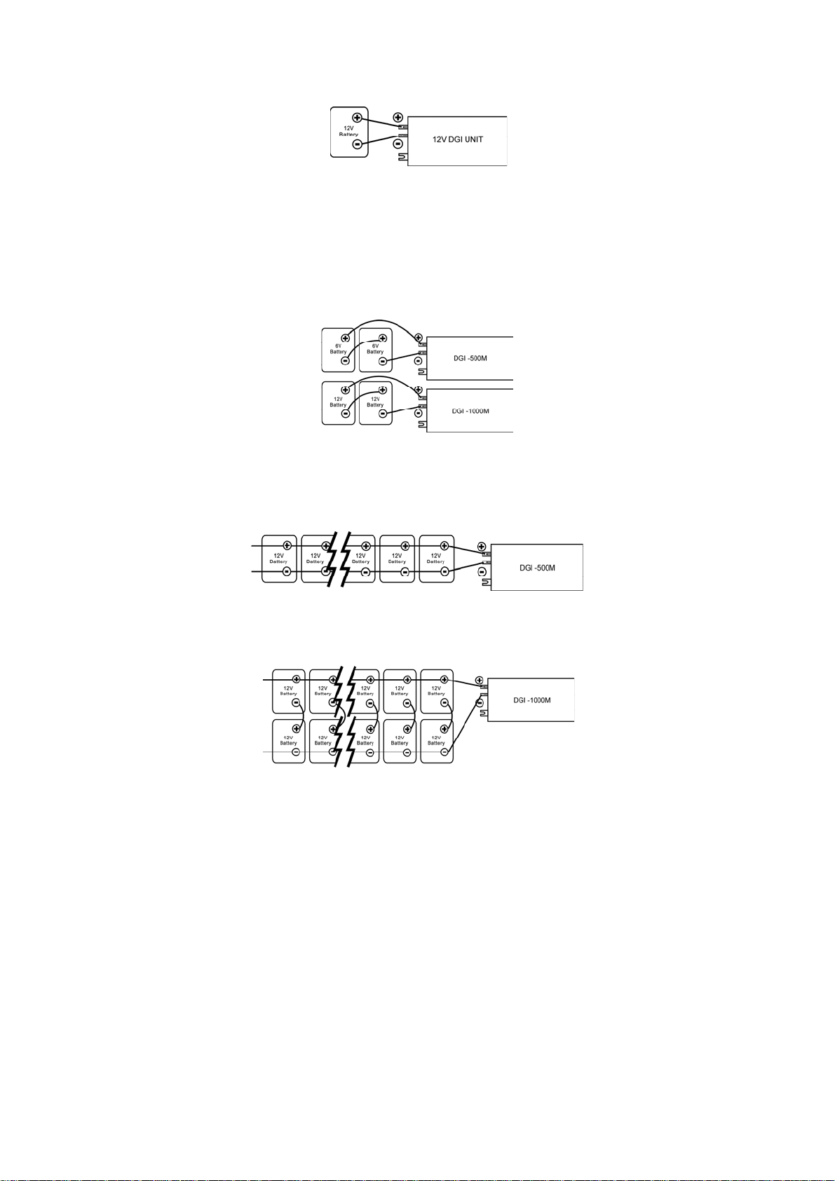
Step 3- Connect battery cables to your batteries
The battery must be wired to match the units DC input voltage specifications
(CPI-500 for 12Vdc, CPI-1000 for 24Vdc).
In addition, the batteries can be wired to provide additional runtime. The
various wiring configuration are as follows:
zSeries Connection: Wiring batteries in “series” increases the total output
voltage. This voltage MUST match the DC voltage requirements of the
CiTO unit, or damage may occur to both the CiTO unit and/or the
batteries.
zParallel Connection: Wiring batteries in “parallel” increases the total run
time the batteries can operate theAC loads. The more batteries
connected in parallel the longer the loads can be powered from the CiTO
unit.
zSeries-Parallel Connection: “Series-parallel” configurations increase
both the battery voltage (to match the DC requirements of CiTO unit) and
run-time for operating theAC loads.

AC Connection
Before having AC connection, match the power requirements of connected
devices with the power output of Inverter to avoid overload. Consult a
qualified electrician, and follow local code for the proper wire sizes,
connectors and conduit requirements.
Step 1- A three-station terminal block is provided to make AC input
connections. Remove the cover plate.
Caution!! Be sure that AC source is disconnected before attempting to
connect AC power cables and load to Inverter.
Step 2- Connect the hot wire (black/brown)
of AC input cable to the HOT IN terminal.
Step 3- Connect the neutral wire (white/blue)
of AC input cable to the NEU IN terminal
Step 4- Connect the ground wire
(green) of AC input cable
to the GND IN terminal
Step 5- Tighten screws to affix wires
in terminal block.
Step 6- Cover up theAC Input by the
plastic cover.
Step 7- Simply plug your equipment(s)
into the output receptacle(s).
Step 8- Turn on Inverter when you are
using connected equipment(s).
Figure 5 AC Input Connections

SPECIFICATION
MODEL CPI-500 CPI-1000
CAPACITY VA/W 500VA/300W 1000VA/600W
Nominal Voltage 220~240VAC
Input Voltage Range 90~280VAC
AC INPUT
Nominal Frequency 50Hz or 60Hz (Auto Detection)
Voltage ±15%
Frequency 50/60Hz ±0.1Hz
Waveform Modified Sine-wave
Efficiency (AC toAC) > 95%
OUTPUT
Efficiency (DC toAC) > 80%
BATTERY Nominal Voltage 12Vdc 24Vdc
Charging Voltage 13.7V 27.4V
Charging Current 8A max. 6A max.
CHARGER
Overcharging Protection 14.5V 29V
TRANSFER Transfer Time 8ms typical
Line mode Green LED blinks or lights steadily
Battery mode Yellow LED lights
INDICATOR
Overload/fault Red LED blinks or lights steadily
Low Battery Voltage in
battery mode Buzzing every 2 seconds
Overload Buzzing every 0.5 second.
AUDIBLE ALARM
Fault Buzzing continuously
ENVIRONMENT Temperature 0 ~ 40°C
Dimension (mm) DXWXH 224x255x80
PHYSICAL Net Weight (Kg) 1.7

Troubleshooting
Problem Possible Cause Remedy
Battery discharged
C
harge battery for 8
h
ours or more.
Battery defect Battery replacement.
No LED display
Power switch is not
pressed Press and hold power
switch.
AC Input is missing
C
heck AC input
c
onnection.
Mains normal but
works in inverter
mode Input protector is
effective Reset the input
protector.
Alarm buzzer beeps
continuously Overload
V
erify that the load
m
atches the capability
s
pecified in the specs.
Overload
Remove some
n
on-critical load.
Back up time is
shorten Battery voltage is too low.
C
harge battery for 8
h
ours or more.
If any abnormal situations occur that are not listed above, please call service
technician immediately.
This manual suits for next models
1
Table of contents
Popular Inverter manuals by other brands


Fimer
Fimer UNO-DM-6.0-TL-PLUS-US-Q Quick installation guide

CPS
CPS SCA Series Installation and operation manual

Generac Power Systems
Generac Power Systems G007144 Installation guidelines

Omron
Omron SYSDRIVE 3G3IV Installation instructions manual

Spectron
Spectron SE1450 Operating and maintenance manual

Hoymiles
Hoymiles HMS-300-1T user manual