Spectron SE1450 Operating instructions

SE1450 DASH Stroke Generator
Operating and Maintenance Manual Page 1 of 25
SPECTRON
SE1450 DASH
STROKE GENERATOR
OPERATING AND MAINTENANCE MANUAL
(Version - 073004)
Spectron Engineering, Inc.
Denver, Colorado
073004

SE1450 DASH Stroke Generator
Operating and Maintenance Manual Page 2 of 25
Caution
Ensure that all cables are properly
attached and secured before turning on
power.
Do not remove the covers on the
SE1450 DASH Stroke Generator except
for Power Supply removal/replacement
as described within. Removal of these
covers will necessitate factory
recalibration and may cause damage.
073004

SE1450 DASH Stroke Generator
Operating and Maintenance Manual Page 3 of 25
Table of Contents
Chapter One - Overview
SE1450 DASH Stroke Generator .............................................................. 5
Chapter Two - Initial Setup and Connections
Typical System Components and Cables .................................................. 7
Setup Procedures ....................................................................................... 8
Communication and Data connections.................................................. 8
Power connection .................................................................................. 9
RS232 Connection and Protocol ................................................................. 9
Chapter Three - Operations
Preliminary Check - Before Power Up ....................................................... 11
Initial Power Up ........................................................................................ 12
Built In Test (BIT)............................................................................ 12
Warm Up Recommendation............................................................. 12
On-Site Alignment and Calibration .......................................................... 12
Automatic Operations ................................................................................ 12
Manual Operations ..................................................................................... 13
RS232 Communications ................................................................. 13
IEEE488 Communications .............................................................. 14
General Command Format Notes ............................................................. 14
073004

SE1450 DASH Stroke Generator
Operating and Maintenance Manual Page 4 of 25
Chapter Four - Maintenance and Repair
Maintenance................................................................................................ 16
Repair .......................................................................................................... 16
Removal and Replacement of the Power Supply ..................................... 16
Troubleshooting .......................................................................................... 17
Replaceable Modules .................................................................................. 17
Factory Contact........................................................................................... 17
Appendix A – Specifications
Appendix B – BIT Logic and Troubleshooting
Appendix C – NIST Traceability of the SE1420 DASH and SE1450 DASH
Appendix D – SE1450 DASH – J5 Pinout Definition
073004

SE1450 DASH Stroke Generator
Operating and Maintenance Manual Page 5 of 25
Chapter One
OVERVIEW
SE1450 DASH
STROKE GENERATOR
Spectron Engineering’s high-performance SE1450 DASH Stroke Generator (SE1450 DASH) has been
designed to display very accurate cursive images on a Head Up Display (HUD). This is a vital
prerequisite to accurately and objectively measuring HUD image performance parameters.
SE1450 DASH Stroke Generator Front View
The SE1450 DASH is designed to generate a linear ramp at the both slow and fast HUD specified
writing speeds. The linearity of the ramp defines the brightness uniformity along the length of the
stroke line. A HUD specified failed writing speed can also be generated and used to test the phosphor
protect circuitry of the HUD.
073004

SE1450 DASH Stroke Generator
Operating and Maintenance Manual Page 6 of 25
The SE1450 DASH is also designed to very accurately position stroke written lines on the HUD.
Horizontal lines are positioned vertically, and vertical lines are positioned horizontally, to a 16 bit
accuracy. This 16 bit accuracy is actively calibrated through appropriate use of the ADJust Command
(see, Manual, Spectron Control Language Commands, SE1450 Stroke Generator) to compensate for
the loading of each individual HUD and its associated interconnections. The accuracy of the SE1450
DASH is NIST traceable
The SE1450 DASH can be programmed to combine a series of user defined lines. There are horizontal
and vertical lines available in three line lengths as well as preprogrammed patterns for a crosshair and
a raster patch. The crosshair is a single control language command that combines a vertical and
horizontal line intersecting on a user defined center position. The raster patch is also a single
command language call. It combines 33 horizontal lines or 33 vertical lines with a user defined center
position and center-to-center line spacing. The raster patch is a convenient image for Resolution,
Contrast and Modulation Factor testing. The lines, crosshairs and raster patches can be combined to
form more complex test patterns.
The SE1450 DASH has an extensive Built-In-Test (BIT), is able to communicate both RS232 and
IEEE488 and is capable of diagnosing Input functionality of the necessary HUD generated signals (DU
Busy and Symbol Command) as well as the other HUD required signals (modified RS170 and Symbol
Mode).
073004

SE1450 DASH Stroke Generator
Operating and Maintenance Manual Page 7 of 25
Chapter Two
INITIAL SETUP and CONNECTIONS
SE1450 DASH
STROKE GENERATOR
The SE1450 DASH is composed of one module and associated cabling. In addition to the
cables, the only field replaceable part of the SE1450 DASH is the Power Supply as
described below in Chapter 4, Maintenance and Repair.
Typically, the SE1450 DASH is operated in association with an automated display
measurement system such as the Spectron SE1420 DASH Display Measurement System
to objectively measure and characterize the performance parameters of the resultant
HUD image. It is this configuration and operation that will be described in this manual,
however, with proper input and cabling, the SE1450 DASH could operate independently
of the measuring system.
Typical System Components and Cables
Table 2-1
Main Module and Replaceable Part Part Number
DASH Stroke Generator
Power Supply
SE1450
SE3022-01D
Associated Cables Part Number
HUD/Test Station Connect cable
External Sync Cable
Standard IEEE488 Cable
Standard RS232 Standard Cable
120 VAC Power Cord
Customer Supplied
OMS-3430
Customer Supplied
Customer Supplied
WAC4
073004

SE1450 DASH Stroke Generator
Operating and Maintenance Manual Page 8 of 25
Setup Procedures
Carefully remove the SE1450 DASH and associated cabling from their shipping cartons
and begin the setup procedures described below. Locate the SE1450 DASH in a secure
location near the Controlling Computer, the SE1420 DASH Display Measurement
System (if used), and the HUD.
Typical SE1450 DASH Stroke Generator Rear View
Communication and Data Connections
1. Determine that the power switch/circuit breaker on the back of the
SE1450 DASH is OFF (See Power Connection, directly below).
2. Connect the HUD/Test Station Connect Cable from Connector J5 on the
back of the SE1450 DASH to the appropriate Connectors on the Test
Station and HUD.
3. Connect the External Sync Cable from Connector J2 on the back of the
SE1450 DASH to the External Sync In on the Display Measurement
System (Normally Connector J2 on the back panel of the SE1420 DASH
Display Measurement System Controller.)
4. Connect the RS232 Cable and/or the IEEE488 Cable for communication
from Connector J4 and/or the IEEE488 Connector respectively on the
back panel of the SE1450 DASH and to the appropriate port(s) on the
Controlling Computer.
073004

SE1450 DASH Stroke Generator
Operating and Maintenance Manual Page 9 of 25
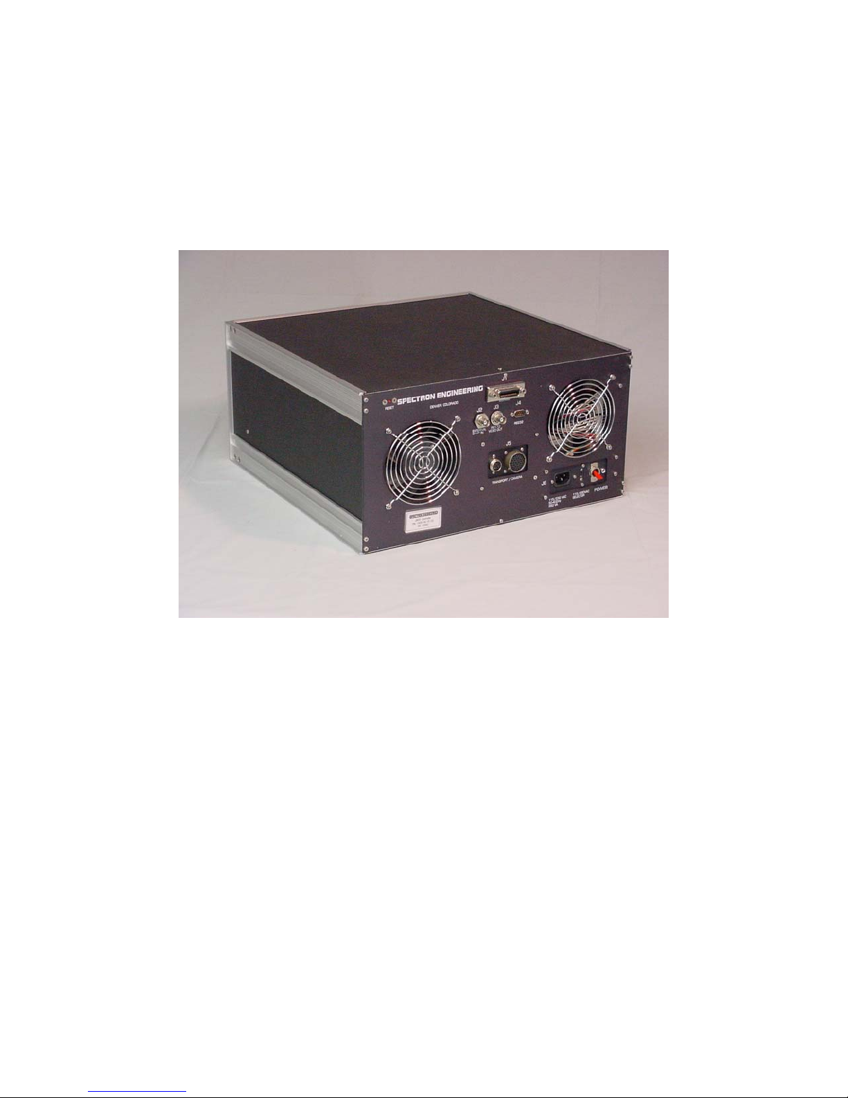
Power Connection
Power Section - SE1450 DASH Stroke Generator Back Panel
1. Determine that the power switch/circuit breaker on the back of the
SE1450 DASH is in the OFF (down) position and that the 115/230 VAC
selector switch is in the correct position for the power source to be used.
2. Connect the 120 VAC Power cord to the back of the SE1450 DASH,
Connector J6, and plug into the power outlet.
3. The system is powered up by turning on the power switch/circuit breaker
on the back of the Controller and operated according to the procedures in
Chapter 3, Operations of this manual.
RS232 Connection and Protocol
User supplied and initiated RS232 Communications with the SE1450 DASH system are
described in Chapter 3, Operations. The following information is supplied as an aid in
initiating proper communications through the RS232 port.
The RS232 connector is a DB9 male connector located on the SE1450 DASH Back Panel
(J4). Only five of the nine pins are used in accordance with the pin out specifications in
table 2-1, below.
Table 2-1
1450 DASH Connection Terminal Connection
Pin 2 RD Receive Data TRANSMIT
Pin 3 TD Transmit Data RECEIVE
Pin 5 GND Ground GROUND
Pin 7 RTS Request to Send CLEAR TO SEND
Pin 8 CTS Clear to Send REQUEST TO SEND
Complete instructions for using the RS232 port are contained in Chapter 3, Operations.
073004

SE1450 DASH Stroke Generator
Operating and Maintenance Manual Page 10 of 25
The RS232 protocol follows an IBM 9-pin “DTE” standard, which is an ASCII system.
The serial protocol for this system is:
•1 start bit
•1 stop bit
•8 data bits
•9600 baud
•Hardware Flow Control
073004

SE1450 DASH Stroke Generator
Operating and Maintenance Manual Page 11 of 25
Chapter Three
OPERATIONS
SE1450 DASH
STROKE GENERATOR
The SE1450 DASH is operated by issuing Spectron Control Language Commands (SCL),
(see, Manual, Spectron Control Language Commands, SE1450 Stroke Generator), either through
RS232 or IEEE488 communications from a Controlling Computer. The commands may
be entered in, 1) automatic mode, with command and data information controlled by user
or Spectron Engineering, Inc. created software, or 2) command mode, with SCL
Commands directly entered by the operator.
Whether operations are performed automatically or manually, the precisely generated
image appears on the HUD and may be viewed and characterized using an independent
measuring system such as the Spectron SE1420 DASH Display Measurement System to
objectively determine HUD performance parameters.
This chapter will primarily describe the operation and testing procedures for manual
operation using Spectron Control Language Commands. Automatic testing may be
accomplished by software that sends sequential Spectron Control Language Commands,
and captures the resulting data as it is generated, according to specific test procedures
for the HUD UUT (Unit Under Test).
Preliminary Check – Before Power Up
At a minimum, the HUD/Test Station Connect Cable, the External Sync Cable, the
120VAC Power Cord, and either the RS232 Cable or the IEEE488 Cable must be
connected as described in Chapter 2, Initial Setup and Connections, prior to commencing
operations as described below.
Other connections, particularly those required to power up the UUT and any Display
Measurement System used to measure and characterize the resulting image, may be
made prior to power on, but are beyond the scope of this manual and are not necessary
for a successful BIT (Built In Test) to be completed during power up.
The operator should become completely familiar with the IST and TST Commands, (see,
Manual, Spectron Control Language Commands, SE1450 Stroke Generator) to view the
results of the BIT and/or the status of the UUT prior to commencing further operations.
073004

SE1450 DASH Stroke Generator
Operating and Maintenance Manual Page 12 of 25
Initial Power Up
Built In Test (BIT) (For BIT Logic and Troubleshooting, see Appendix B)
The power switch/circuit breaker is located on the back panel of the SE1450
DASH near the AC power cord connector. After all Setup and Connect
procedures described in Chapter 2, Initial Setup and Connections
have been completed, the power switch may be turned on. This will
initiate a system reset and the BIT will run.
The BIT will be accomplished each time the system is turned on or reset. It
tests the electronic circuitry and function of the SE1450 DASH and tests for
the presence of the HUD functions necessary to the generation of a precise
and calibrated image on the UUT.
Use the IST and TST Commands, above, to determine the status of the
SE1450 DASH and the necessary external circuitry.
Warm Up Recommendation
In order to allow all components to reach a consistent operating
temperature, the SE1450 DASH should be turned on approximately 30
minutes prior to use
On-Site Alignment and Calibration
The SE1450 DASH is precisely calibrated at the Factory to NIST Standards and 16 bit
accuracy. In order to obtain full Factory Specifications in the field, however, it is
necessary for the Operator to fully understand and execute the ADJust command for
each individual UUT. This is necessary for the SE1450 DASH to compensate for the
actual loading of the UUT and its associated interconnections.
Other commands will allow the Operator to accurately position the precision images
generated by the SE1450 DASH on the UUT according to user defined requirements for a
particular test procedure.
Automatic Operations
The SE1450 DASH system is capable of generating a precise image by responding and
replying to all Spectron Control Language Commands (see, Manual, Spectron Control
Language Commands, SE1450 Stroke Generator) via the IEEE488 bus or RS232 port.
Automatic routines for generating a series of specific test patterns are not included with
the SE1450 DASH, however, they may be created by the user of the system or separately
contracted from Spectron on an optional basis.
073004

SE1450 DASH Stroke Generator
Operating and Maintenance Manual Page 13 of 25
Manual Operations
To perform manual operations, connect a controlling computer to the RS232 port on the
SE1450 DASH. Alternatively, a properly configured computer can communicate with the
SE1450 DASH through the IEEE488 bus connection. Use of the IEEE488 bus will
effectively override and disable the RS232 port. This section will describe the necessary
communications relationship between the controlling computer and the SE1450 DASH
for successful operation of the system.
RS232 Communications
All of the Pattern Generating, Design and System commands described in the
Manual, Spectron Control Language Commands, SE1450 Stroke Generator can be
performed via the RS232 port using a Controlling Computer.
Important Note
All SCL Commands in Serial (RS232) operation must be
preceded with a colon (:) to indicate “Command Mode” to the
SE1450 DASH (see, General Command Format Notes, below).
Caution: Failure to precede a SCL Command with a colon (:)
in Serial Operation may lead to unpredictable results,
including having to reset the System before proceeding.
Note
To perform a Hardware Reset, power
down the system, then re-start it or
Press the recessed Red RESET Button
on the SE1450 DASH Back Panel.
All transmissions between the SE1450 DASH system and the controlling computer
are in ASCII code. Commands that are sent via the RS232 interface return data
in their own distinct format. All SCL Commands, and any associated parameters,
must be followed by a Carriage Return and a Line Feed.
After entry of a colon (:), any ASCII input of the first 3 significant characters
corresponding with a valid SCL command will cause the appropriate function to be
implemented.
Complete description of the RS232 port, wiring information, and protocols are
provided in Chapter 2, Initial Setup and Connections, above.
073004

SE1450 DASH Stroke Generator
Operating and Maintenance Manual Page 14 of 25
IEEE488 Communications
IEEE488 (GPIB) operations are commenced by properly connecting a Controlling
Computer to the SE1450 DASH and sending ASCII character strings to the
SE1450 DASH using the GPIB interface software on the computer. Once in GPIB
Mode, RS232 Communication is disabled and the SE1450 DASH functions as a
“slave” to the Controlling Computer until such time as GPIB control is
relinquished.
The exact method of controlling SE1450 DASH operations will vary according to
the GPIB interface being used, however, VALID Spectron Control Language
commands as described in Manual, Spectron Control Language Commands, SE1450 Stroke
Generator, must be sent as string data to the SE1450 DASH by the GPIB interface
software. Under GPIB control, the SCL Command MUST NOT be preceded
by a colon (:). All character strings sent to the SE1450 DASH will provide a
report for that string. The GPIB interface software must request and interpret
this reported data for proper interactive operation.
General Command Format Notes
Whether operating in Automatic or Manual mode, it is essential for the Operator to have
a complete understanding of the format and function of all commands in the Manual,
Spectron Control Language Commands, SE1450 Stroke Generator. The format rules from that
Manual are repeated here for clarity of operation:
1. Serial Operation vs. IEEE488 Operation - Spectron Control Language Commands (SCL
Commands) are entered directly as specified below during IEEE488 operation. If the SE 1450
Stroke Generator is being controlled through the Serial Port, however, the “Command Mode”
must be entered by preceding each Command with a colon ( :); i.e. READ is a valid command
in IEEE488 Operation, :READ is valid in Serial Operation.
Caution: Failure to precede a SCL Command with a colon ( : ) in Serial Operation
may lead to unpredictable results, including having to reset the System before
proceding.
2. Only the First 3 Characters of a Command are Significant - The READ command above
will be recognized as valid if the user types REA, READ, REAxxx in IEEE488 Operation, or if the
user types :REA, :READ, :REAxxx in Serial Operation. If the first 3 characters of a command are
not recognized as valid; i.e. the user types REED, a “BAD COMMAND” response will be
generated and no futher action will be taken by the System.
3. Separate a Valid Command from the Parameters associated with the Command with One
or More Spaces <sp>. Likewise, Separate Multiple Parameters with One or More Spaces
<sp> - The CENTER command requires two parameters representing the X and Y offset
voltages (see Summary, below), and would be entered as follows: CENTER<sp>-
.532<sp>1.217.
073004

SE1450 DASH Stroke Generator
Operating and Maintenance Manual Page 15 of 25
4. Multiple Commands MAY NOT be Entered on the Same Line, However, Multiple
Pattern Generating Commands may be Created, Viewed, Edited, Saved, and Recalled
Through Appropriate use of the ADD, READ, EDIT, SAVE, and LOAD Commands and
with a Working Understanding of how the Current Work Area, Described Directly
Below, Functions.
5. The Current Work Area Allows Complicated Images to be Created, Edited, Saved and
Recalled by Storing a Series (31 maximum) of SLINE, SCROSS and SPATCH
Commands - Directly entering a pattern generating command, such as SLINE, SCROSS, or
SPATCH, will clear the Current Work Area and create a Line 1 in the Area reflecting the
command entered. Further enhancements to the image pattern are generated using the ADD
command which, with appropriate parameters, will add Line 2, Line 3, … Line 40 to the
Current Work Area.
Caution: Inadvertently issuing a pattern generating command directly at this
point, rather than using the ADD command consistently, will clear the Current
Work Area, as above described, and will result in the loss of the previously created
elements of the final image pattern.
The series of pattern generating commands in the Current Work Area can be viewed using the
READ command, changed by using EDIT, deleted with the DELETE command, and
permanently stored (in EEPROM) in one of 20 numbered locations using the SAVE command.
The command series can later be retrieved into the Current Work Area with the LOAD
command.
The SE 1450 Stroke Generator generates a live image based on the contents of the Current
Work Area.
Caution: If the complete series of pattern generating commands in the current
work area cannot be displayed due to the constraints of the time slot allocated for
display generation, the ‘IMAGE TRUNCATED, IN SYMBOL MODE’ or the
[IMAGE TRUNCATED, IN W/RASTER MODE] message will be generated as the
last report line of the READ command. If the complete series of pattern
generating commands is displayed, the ‘IMAGE COMPLETE. IN SYMBOL
MODE’ or the ‘IMAGE COMPLETE, IN W/RASTER MODE’ message will be
generated as the last report line of the READ command.
073004

SE1450 DASH Stroke Generator
Operating and Maintenance Manual Page 16 of 25
Chapter Four
MAINTENANCE and REPAIR
SE1450 DASH
STROKE GENERATOR
The SE1450 DASH is designed to make maintenance and repair as simple as possible.
Each time the system is turned on or reset, it performs a self-diagnostic test called a BIT
(Built In Test) that checks the electronic circuitry and connections in the SE1450 DASH
(see, Chapter 3, Operations), above.
Maintenance
No routine maintenance procedures by the operator are required for the SE1450 DASH
as long as the unit passes the BIT.
Repair
No repair of the SE1450 DASH system is permitted by the user of the system other than
the removal and replacement of the Power Supply as described below. User initiated
repairs will void the factory warranty and invalidate the factory calibration. In no event
should the user attempt to remove factory installed covers and access the internal parts
(other than to replace the Power Supply Module). Should it appear that repairs are
required, contact Spectron Engineering, Inc. as specified below.
Removal and Replacement of the Power Supply
The procedure for removal and replacement of the Power Supply is as follows:
1Disconnect the power cord from the SE1450 DASH.
2Remove the top cover of the SE1450 DASH.
3Disconnect the 4 latched cable connectors from the Power Supply.
4Remove the nylon cable tie that anchors the latched cables to the Power Supply
angle strut.
5Disconnect the in-line connector in the green chassis ground wire that connects
to the transformer mounting screw. Note: The transformer mounting screw
does NOT need to be removed.
073004

SE1450 DASH Stroke Generator
Operating and Maintenance Manual Page 17 of 25
6Remove the #6-32 x ½” socket head cap screws (5 ea.) that attach the Power
Supply to the lower right area of the SE1450 DASH back panel.
7Carefully remove the Power Supply from the SE1450 DASH.
8Reverse these directions to install the new Power Supply.
Troubleshooting
If any of the modules fail the BIT, follow these general troubleshooting steps after
power is turned off:
1. Check to ensure that all cables are properly seated and connected. The most
common reason for BIT failure is the improper connection of the SE1420 DASH
system cables.
2. Check the proper functionality of all units connecting to the SE1450 Dash to
include the Controlling Computer and the UUT.
3. Turn the power on and carefully monitor and record the results of the BIT with
the IST and TST commands. Note the exact “fail” indications from these
commands and follow the specific troubleshooting directions found in Appendix
B, BIT Logic and Troubleshooting.
4. If the procedures in Appendix B do not resolve the problem, contact Spectron
Engineering, Inc., as specified below, with the specific circumstances and
failure indications reported by the BIT for further instruction and safe
troubleshooting steps for the error condition encountered.
Replaceable Modules
In the SE1450 DASH system, a module is defined as a minimum replaceable component.
Other than the SE1450 DASH itself, there is one internal module (Power Supply), three
cables and a power cord that can be replaced (see, Chapter 2, Initial Setup and
Connections, Typical System Components and Cables).
Factory Contact
If the user of the SE1450 DASH encounters problems that cannot be solved by the above
procedures, or if any other problems exist, contact Spectron Engineering, Inc. as follows:
Spectron Engineering, Inc.
255 Yuma Court
Denver, CO 80223
Telephone (303) 733-1060
Fax (303) 733-2432
073004

SE1450 DASH Stroke Generator
Operating and Maintenance Manual Page 18 of 25
APPENDIX A
SPECIFICATIONS
SE1450 Stroke Generator for T-50 HUD
For Definition, Specification and System Interaction of the Stroke Generation Requirements, refer to
the following BAE SYSTEMS, AVIONIC SYSTEMS Document:
INTERFACE CONTROL DOCUMENT (ICD)
FOR THE
T-50 PRODUCTION INVESTMENT (PI)
HEAD UP DISPLAY (HUD) SYSTEM
Stroke Generator Specific Signals
Signal Label: XDEF
Signal Name: X Symbol Deflection
Signal Type: Analog
Source: Stroke Generator
Destination: PDU (T-50 HUD)
Voltage Range: -12 to +12 Volts DC Differential Line to Line
Parameter Range: ± 18 Degrees, 36 Degree Total Field of View
Scale Factor: 1.5 Degree per Differential Volt
Accuracy: ± 0.010 Volts at 0.0 Volts
± 0.025 Volts at ±4.0 Volts Differential
± 0.028 Volts at ±6.6 Volts Differential
Signal Label: YDEF
Signal Name: Y Symbol Deflection
Signal Type: Analog
Source: Stroke Generator
Destination: PDU (T-50 HUD)
Voltage Range: -10 to +10 Volts DC Differential Line to Line
Parameter Range: ± 15 Degrees, 30 Degree Total Field of View
Scale Factor: 1.5 Degree per Differential Volt
Accuracy: ± 0.010 Volts at 0.0 Volts
± 0.025 Volts at ±4.0 Volts Differential
± 0.028 Volts at ±6.6 Volts Differential
073004

SE1450 DASH Stroke Generator
Operating and Maintenance Manual Page 19 of 25
Writing Speed
X & Y Deflection Rate Accuracy
Slow Cursive 1.221 ms per 30 degrees ± 5%
Fast Cursive 111 µs per 30 degrees ± 5%
Fail Rate 7.995 degrees per 1 ms ± 5%
Discrete – Standard Low Level Complementary Signal Types
From Stroke Generator to PDU (T-50 HUD)
Signal Label Signal Name
IMDCBUSY IMDC Busy
BU Bright Up
Discrete – Standard Low Level Complementary Signal Types
From PDU (T-50 HUD) to Stroke Generator
Signal Label Signal Name
DUBUSY PDU Busy
SYMCMD Symbol Command
Discrete – Standard Low Level Complementary Signal Type
From Test Station to Stroke Generator
Signal Label Signal Name
SYMODE Symbol Mode
Video - Modified RS170
From Test Station to Stroke Generator
Signal Label Signal Name
SELVID Selected Video
For X & Y Symbol Deflection waveform requirements refer to APPENDIX B, HEAD UP DISPLAY
AIRCRAFT SYSTEM INTERACTION in the ICD defined above.
The Stroke Generator and DASH Measurement System passed-through metrology verification are
defined in Appendix C, NIST Traceability of the SE1420 DASH and SE1450 DASH.
A Synchronization Pulse (stripped from the Test Station supplied RS170 video) is available as an
output from the SE1450 Stroke Generator Sync Connector. This TTL pulse supplies the HUD
External Sync to the SE1420 DASH Display Measurement System.
073004

SE1450 DASH Stroke Generator
Operating and Maintenance Manual Page 20 of 25
APPENDIX B
BIT Logic and Troubleshooting
1. No Answer - using IEEE 488 (GPIB) or RS232 communication.
A. Physically go to the back panel of the Display Measurement Controller. Check for the
proper connection of the GPIB (IEEE488) and/or the RS232 Cables at both ends.
B. While at the back panel, check to see if the red LED (Power ON Indication) is on.
1) If the LED is off, check the Power On Switch, A/C Power Cord connections at both
ends and the A/C Source. If these actions do not light the LED, replace Power Supply
Module.
2) If the LED is on, first check to see if the Stroke Generator to BAE Station Cable is
connected at both ends. Next, measure the Stroke Generator Power Supply Reference
Signals at the BAE Station. If these values are within specification, replace/repair the
Stroke Generator. If these numbers are out of specification, replace the Power Supply.
2. Failure Reports
A. From STA(tus) Report = 61' STATUS FAIL - XPORT; RERUN ISTEST BEFORE
REPAIR -or- 62' STATUS FAIL - CAMERA; RERUN ISTEST BEFORE REPAIR -or- 63'
STATUS FAIL - CONTROLLER; RERUN ISTEST BEFORE REPAIR -or- 64' STATUS
FAIL - POWER SUPPLY; RERUN ISTEST BEFORE REPAIR. Rerun the ISTEST and then
request status report with a STATUS. If the same report is received, the Module specified in
the report should be repaired/replaced.
B. From AST(atus) Reports
1). Failure report = 51' ASTATUS FAIL - CHECK ACCESSORY & RERUN
ALIGN BEFORE REPAIR. This failure report will occur if the accessory cable is not
properly connected to the HUD Simulator or HUD Holding Fixture or if the EEPROM
can not be read/written. First, verify that the appropriate accessory being used in the
ALIGN is either an T-50 EDU Holding Fixture or an T-50 HUD Simulator. Then check
to see if the accessory cable is properly attached at both ends -- one to the accessory and
the other to the Transport. Next, rerun the ALIGN procedure. If the failure report is
number 51, repair or replace the accessory (and/or accessory cable). If available, a
different accessory and/or accessory cable can be used to break the uncertainty between
accessory failure and accessory cable failure.
2). Failure Report = 52' ASTATUS FAIL - CAMERA, RERUN ISTEST & ALIGN
BEFORE REPAIR. This failure report will occur if there is a camera shutter
malfunction or no camera EOF (End Of Frame) or no VSync for camera timing. Check
to see that all cables are properly connected and then run the Internal Self Test using an
ISTEST command. Request a status report with a STATUS command. If there is a
failure report, refer to 2. A. above. If there is no failure report from the STATUS
report, check the accessory for light path obstructions and that the lenses on the
073004
Table of contents
Popular Inverter manuals by other brands

Potek
Potek PI1000-AP-RED owner's manual

TerraGen
TerraGen TGR installation manual

Tektronix
Tektronix TG700 installation instructions

Ningbo Ginlong Technologies
Ningbo Ginlong Technologies Solis-20K Installation and operation manual

Axpert
Axpert 3KVA-110V Service manual

Goodwe
Goodwe SMT Series Quick installation guide

Mule Lighting
Mule Lighting OSHPD Series Installation and operation manual

Mitsubishi
Mitsubishi FR-A700 Series instruction manual

Envertech
Envertech EVT300 Quick installation guide

Samlexpower
Samlexpower CFB1-200 owner's manual

Whistler
Whistler 200/400 WATT owner's manual

CARLO GAVAZZI
CARLO GAVAZZI G38900014 user manual