City Theatrical AUTOYOKE User manual

752 EAST 133RD STREET BRONX, NY 10454
718/292/7932 800/230/9497 FAX:718/292/7482
www.citytheatrical.com
ver1.0
email: [email protected]
UserManual
AUTOYOKE
withPARNel

TABLE OF CONTENTS
SECTION 1 SPECIFICATIONS
1-1 Dimensions and Weight
1-2 Compliance
1-3 Electrical
1-4 Protocol
1-5 Motors
SECTION 2 SAFETY
SECTION 3INSTALLATION AND SET-UP
3-1 Unpack and inspect the shipping container
3-2 Balancing the System
3-3 Attaching a Color Scroller
3-4 Replacing the PARNel Lamp Housing Assembly on the Unit
3-5 Hanging the AutoYoke
3-6 Power cable
3-7 Data cable
SECTION 4USER INTERFACE
4-1 Menu system
4-2 Address
4-3 Calibrate
4-3a Calibrate All
4-3b Calibrate a single attribute
4-3c AutoCalibrate
4-4 Invert
4-5 Resolution
4-5a 8 bit or 16 bit
4-5b DMX Smoothing values
4-6 Pan, Tilt, and Focus Limits
4-7 Software release
4-8 LED Display
4-8a Timeout
4-8b Brightness
4-9 Restore factory defaults
4-10 Error messages
p. 1
p. 2
p. 2
p. 2
p. 2
p. 3
p. 4
p. 5 - 6
p. 7 - 9
p. 10
p. 11
p. 11
p. 11
p. 12
p. 13
p. 14
p. 14
p. 15
p. 15
p. 16
p. 17
p. 17
p. 18
p. 19
p. 21
p. 21
p. 21
p. 22
p. 22
p. 23

SECTION 5OPERATION
5-1 DMX channel assignments
5-2 Pan and Tilt
5-3 Default setting
5-4 Personality settings
5-5 Control channel
5-6 Encoders
SECTION 6BEAMSPREAD AND COLOR CONTROL
AutoFocus
Scrollers
SECTION 7MAINTENANCE
Software revisions
Spare parts
Lighting fixture
SECTION 8 WARRANTY
Limited Warranty
Procedure
*** Trouble Shooting Guide and Balancing Guide are located after page 28.
p. 24
p. 24
p. 25
p. 25
p. 26
p. 27
p. 27
p. 27
p. 28
p. 28
p. 28
p. 28
p. 28


1-2COMPLIANCE
Conforms to UL STD 73, Eighth Edition - Motor Operated Appliances.
Certified to CAN/CSA C22.2 NO.: 68.92
ETL# 9801635
CETL# 9801635
CE, GS,
1-3ELECTRICAL
· Working voltage: 100-240 VAC, 50/60 Hz
· Rated current: 1.3A
1-4PROTOCOL
· USITT DMX512
· Start code: (00h)
· Maximum load: 32 fixtures per DMX link (See Section 3-7, Data Cable)
· Maximum length of DMX link: 2000'(See Section 3-7, Data Cable)
· Required control channels: 7 (16-bit) or 5 (8-bit)(See Section 3-7, Data Cable)
· Termination: 120Ω(See Section 3-7, Data Cable)
1-5MOTORS
· High torque stepper motor, half stack
· Rated voltage DC: 8.7
· Step angle (degrees): 1.8
-2-

SECTION 2: SAFETY
· A moving light is a dangerous piece of equipment. It is for professional use only.
· If the supply cord is damaged, it must be replaced by the manufacturer or its service agent or a similarly
qualified person in order to avoid a hazard.
· Follow all safety procedures that apply to the lighting fixture, per its manufacturer’s instructions.
1. Refer to the lighting fixture’s user manual for all applicable safety information.
2. Maintain minimum safe distances.
· The AutoYoke with PARNel is designed for use only with the ETCSource Four PARNel. Using a fixture
other than the ETC Source Four PARNel WILL VOID THE AUTOYOKE WARRANTY.
· Always ground (earth) the AutoYoke electrically.
· Balance of the lighting fixture as mounted in the AutoYoke is critical to proper operation of the AutoYoke.
Attempting to operate the AutoYoke while the lighting fixture is out of balance presents a significant risk
of inaccuracy, increased motor noise and component failure. See Section 3-4, Balancing the System,
for complete information.
· Never lift the AutoYoke by the lighting fixture. Always lift and carry the AutoYoke by its two
handles, located on the sides of the power supply.
· Always suspend the AutoYoke from approved clamps secured to the designated points on the AutoYoke
power supply. See Section 3-5, Hanging the AutoYoke, for further information.
· Always use an approved safety cable when hanging the AutoYoke.
· Always disconnect the AutoYoke from AC power before service.
· Do not use DMX accessories that are not cited in this manual due to possible electrical incompatibility
with the AutoYoke.
· Do not allow the AutoYoke or its accessories to come into contact with moisture.
· Do not put flammable materials on or near the AutoYoke.
-3-

SCROLLER
SCROLLER
control panel
handle
power supply
yoke
side arms
Source Four PARNel
connector box
SECTION 3: INSTALLATION AND SET-UP
WARNING: Using a fixture other than the ETC Source Four PARNel with the AutoYoke
WILL VOID THE AUTOYOKE WARRANTY!
3-1 UNPACK AND INSPECT THE SHIPPING CONTAINER
Addtional hazards include the following:
- Damaging both the AutoYoke and the lighting fixture
- Fixture detaching from the AutoYoke
- Fire hazard
Verify that the AutoYoke has arrived complete and undamaged.The shipping container
should contain the following items:
- (1) AutoYoke with ETC Source Four PARNel
- (1) User's Manual
- 4 -

3-2 BALANCING THE SYSTEM
- 5 -
The AutoYoke with PARNel must be correctly balanced to insure proper operation. Follow the steps described be-
low. There are a total of 6 (six) mounting holes, 3 (three)located on each side arm. They are arranged in a triangle
with the point of the triangle facing backwards. Use 1/4-20 x 1/2 -inch long, pan head screws in all of the mounting
holes. Failure to do so may result in poor performance of the of the AutoYoke. There are extra holes that are not
marked in the Balancing Guide to allow for balancing of the unit in the future for other accessories that were either
not available or not used when the Balancing Guide was published.
a) Refer to Balancing Guide table and figure at the last page of this manual.
b) Locate along the top of the table which color scroller will be used.
c) Locate along the side of the table which accessory will be used, if any.
*Note: Not all accessories are usable with all color scrollers. The combinations that are not valid are
marked with an "N A" (not applicable) in the table.
d) The intersection of the color scroller column and the accessory row will determine which set of holes
to use in the side arms for the proper balancing of the system.
e) Mount the PARNel-cradle assembly to the side arms usingthe set of holes determined from the previous
step. Make sure that the cradle is square with respect to the side arms.
f) Mount and secure the color scroller (if any) to the PARNel fixture and connect scroller to the connector box
of the AutoYoke. Please refer to Section 3-3, Attaching a Color Scroller/ Accessory, for instructions.
g) Mount and secure the accessory (if any). Refer to Section 3-3, Attaching a Color Scroller/ Accessory, for
instructions.
h) Tighten all hardware.
i) The lighting fixture is balanced when it free drifts to a near horizontal position (perpendicular to the Auto-
Yoke) or slightly front heavy.Operating an imbalanced AutoYoke will result in inaccuracy.
mounting screws
side arm

- 6 -
Some examples are as follows:
EXAMPLE 1
You will use the system without a color scroller and with or wothout a color frame. Look in the table for No
Scroller and No Accessory or Color Frame. The table will show that the PARNel-Cradle assembly shouldbe mounted
to the side arms using the #1 set of holes. This is the default configuration when the unit is shipped from the factory
(unless special instructions have been provided to have the unit in another configuration prior to shipment). This
allows the user to run the AutoYoke straight from the box.
EXAMPLE 2
You will use the system with a Top Hat but the system is configured/balanced for No Accessory. Begin by
removing the screw at the point of the "V" on one side arm, and loosen the other two screws. Remove all the screws
from the #1 set of holes in the other side arm and loosely reinstall them in the #2 set of holes in accordance to the
Balancing Guide table. Remove the two screws from the #1 set of holes in the first side arm and tightly reinstall them
along with the third screw in the #2 set of holes, while making sure that the cradle is square with respect to the side
arms. Tighten the screws in the other side arm, again making sure the cradle is square. Mount and safety the Top Hat.
*Note: The method cited in Example 2 is only useful when moving from an adjacent set of holes. By leaving
some of the screws in loosely, it allows you to move the PARnel-cradle assembly to the other hole location easily.
If the new set of holes is further than the adjacent set of holes, all of the screws must be removed and reinstalled to
the new location.
EXAMPLE 3
You will use the system with a "Wybron" CXI color scrollerbut the unit is configured/balanced for No Acces-
sory. Look in the table for the CXI color scroller then the top hat. The table will show that the PARNel-cradle assembly
should be mounted to the side arms using the #6 set of holes. Follow steps e through h of the instructions on the
previous page.
CXI Color Scroller- #6 set of holes

- 7 -
3-3 ATTACHING A COLOR SCROLLER
A color scroller is an optional accessory, and is not supplied by City Theatrical, Inc. See Section 6 for
further information.
THE AUTOYOKE SUPPORTS THE WYBRON FORERUNNER, WYBRON CXI (See cable note below),
WYBRON COLORAM II (See cable note below), RAINBOW PRO SERIES, AND CHROMA Q M-1 COLOR
SCROLLERS. THE AUTOYOKE SUPPLIES POWER TO THE SCROLLER; OTHER MANUFACTURER’S
SCROLLERS ARE NOT ELECTRICALLY COMPATIBLE. ATTEMPTING TO USEA SCROLLER OTHER THAN
THOSE LISTED ABOVE WILL POTENTIALLY DESTROY THE SCROLLER.
All AutoYoke-compatible scrollers that are not Wybron CXInor Wybron Coloram II are referred to in this
manual as direct DMX scrollers.
See Section 4-2 for addressing.
1. Insert the scroller into the lighting fixture gel frame holder.
2. Secure color scroller to the fixture as tight as possible by use of plastic cable ties. This ensures that
the scroller will not move no matter what position it is in. Any extra movement on the scroller while
the unit is moving may cause inaccuracy due sudden weight shifts.
Loop the cables thru the adaptor plates then thru the tabs near the rim of the fixture. Use four attach-
ments points if possible. See pictures below on various attachment styles depending on the choice of
scroller.
CXI, Coloram II
tab
cable tie
adaptor plate

- 8 -
Chroma Q - M1*
* Note that the Chroma-Q M1 is inserted to the fixture upside down due to the location of its data in/out connectors
and due to this, secure the scroller cable to make sure that it does not interfere in any way to the AutoYoke's range
of motion.
PARNel tabs
Rainbow scroller tabs
Rainbow Pro Series 8"*
* For the Rainbow scroller, use the two tabs at the top ofthe scroller as attachment points to the tabs of the PARNel
fixture.

- 9 -
3. Plug an 18" 4-pin XLR cable to the scroller and to the connector box of the AutoYoke.
(Refer to drawing below for view of the connector box)
***Note: City Theatrical does not recommend using a cable that is longer than 18”. Using a scroller cable
that is longer than 18” runs the significant risk of interfering with the AutoYoke’s range of motion.
***Note: When using a Wybron CXI or a Coloram II, the scroller cable must be wired in the following
way:
Male pin 1 to Female pin 4
Male pin 2 to Female pin 2
Male pin 3 to Female pin 3
Male pin 4 to Female pin 1
Using a cable that is not wired this way will destroy the scroller. Always consult the color scroller
manufacturer’s signal cable requirements before connecting a scroller to the AutoYoke.
connector box
4-pin XLR female connector
(scroller out)
USING A TOP HAT OR OTHER ACCESSORIES
Use only the accessories listed in the Balancing Guide (located at the end of the Manual) and secure tightly
to the fixture or to the scroller by means of cable ties whenever possible.
scroller with top hat

3-4 REPLACING THE PARNEL FIXTURE LAMP HOUSING ASSEMBLY ON THE UNIT
- 10 -
The AutoYoke with PARNel is supplied with the lampwire already terminated to the AutoYoke connector
box. However, the lamp housing assembly might need replacing at some point. The cap-wire assembly
may be replaced as follows but be sure that AutoYoke power and the lamp power cables are unplugged.
1. Remove the connector box cover by using a philip's head screwdriver to remove the four
6-32 x 1/4 inch screws, two on each side, and locate the terminal block.
2. Using a 1/8-inch wide slotted screwdriver, loosen thetwo screws from the cells that holds the
two white wires coming from the lamp housing assembly, andpull the two wires out.
3. Using a 5/16-inch socket driver, remove the 6-32 nutthat secures the ring terminal of the ground
wire coming from the lamp housing.
4. Locate the black strain relief and loosen the nut at the outside of the connector box to free up the
wires.
5. Pull out the wire harness from the strain relief.
6. Loosen the knurled knob of the cap and remove the lamp housing assembly from the PARNel fixture.
7. Cut the lamp harness of the new lamp housing assembly to about 13 inches from the cap.
8. Screw the new cap to the PARNel fixture (you may putin the HPL lamp at this point).
9. Slip the nut removed from the strain relief over the new lamp harness and insert the harness into
the strain relief from the outside of the connector box.
10. Strip about 1/4 inch of insulation from the three wires and crimp a ring terminal to the ground
(green) wire. Ring terminal should be for gauge #22-18 and with a #6 hole.
11. Place the new ground wire (with ring terminal) over the stud bolt where the first ground wire was
removed and secure with the 6-32 nut.
12. Insert the two white wires to the terminal block and tighten the screws.
13. With the wires terminated inside the box, tighten the nut of the strain relief from the outside of the
box to secure the lamp harness.
14. Reinstall the connector box cover.
- 11 -
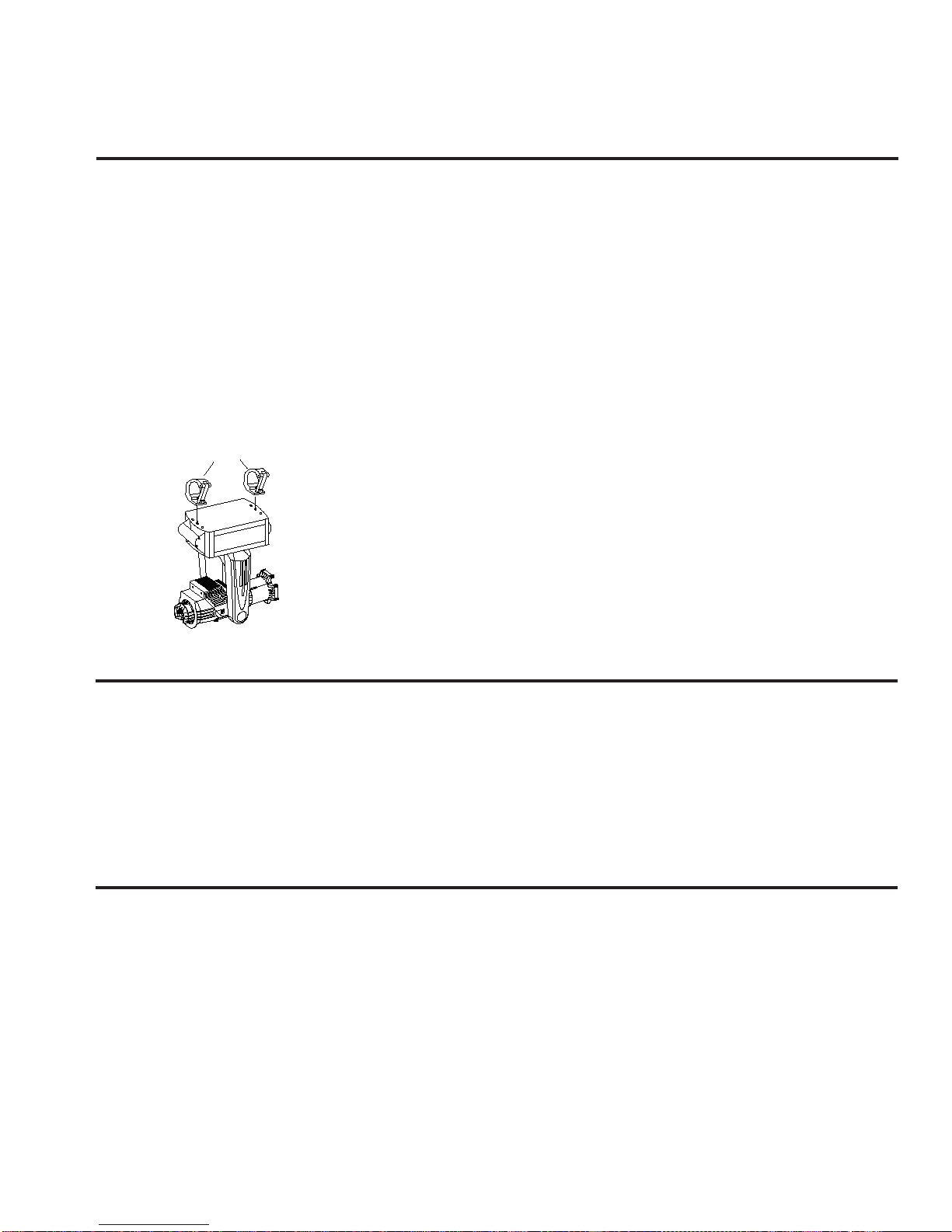
3-5 HANGING THE AUTOYOKE
The AutoYoke must be securely attached to the hanging position with hanging clamps. The Power Supply
must be placed either directly above or directly below the lighting fixture for proper operation (see note
below). A secondary means of suspension, a safety cable - must be used to prevent the AutoYoke from
falling in the event of hanging clamp failure.
***NOTE: The AutoYoke MUST NOT be hung at any angle to avoidimbalance and malfunction of the
unit.
Pan direction is CLOCKWISE from 0% to 100% when the AutoYoke is hanging Power Supply up, facing the
Front Panel, looking at the AutoYoke hanging from below. Keep this in mind when choosing hanging
orientation for optimal travel.
1. Attach the hanging clamps to the specified holes on the top of the
Power Supply.
2. Hang the AutoYoke on a minimum of 2’3” centers and with a clearance
of 3’ from the top of the Power Supply to the fixture and color scroller
(clearance will be greater ifa top hat is used).
3. Fasten a safety cable through one of the handles of the AutoYoke, and
secure it to the hanging position.
3-6 POWER CABLE
AutoYoke: The cable with the three pin Edison connector supplies power to the AutoYoke. Plug to a
NON DIM power supply that is configured for a switchable PSU or a hot circuit that does
not pass through a dimmer rack.
Lamp: The cable with the three pin stage or twist lock connector (or without connector) supplies
power to the lighting fixture. This may be plugged into a dimmer.
3-7 DATA CABLE
Plug a DMX cable to the male 5-pin XLR on the AutoYoke Power Supply.
· Cable must be twisted pair, 120W, shielded EIA485 cable (Belden 9829, 9842 or equivalent),
minimum 22 AWG.
· Recommended maximum cable length is 1640’ (500m). [Recommended Practice for DMX512,
Adam Bennette 1994] Maximum cable length is 2000’ (610m).
· A maximum of 32 DMX receiving devices can be present on a single DMX line.
· The last DMX device on the line must be terminated with a resistor with a value of 120W.
hanging clamps

SECTION 4: USER INTERFACE
4-1MENU SYSTEM
Several of the routines (marked with a * below) that are performed at the front panel are also
accessible from the control channel (See Section 5-4, Control Channel, for further details).
The menu on the front panel of the AutoYoke allows you to do the following:
· Set DMX address
· Calibrate*
· Invert Pan, Tilt, and Focus travel direction
· Select 8- or 16-bit operation
· Select DMX smoothing value
· Set Pan, Tilt, Iris and Focus Limits*
· Display software version
· Invert display
· Change LED display properties
· Restore Factory Defaults (except for DMX512 address and display settings)
· Display Error messages
Throughout this manual, the following conventions will be used to explain menu navigation:
· Menu:The Menubutton allows you to enter the menu item or return to the
upper level menu items.
· Enter: The Enterbutton allows you to select a function.
· st: The arrow keys allow you to navigate into and out of the
menu system.
· AddrAddr:Menu items that appears on the LED display on the front
panel will be presented in this format.
-12-

SECTION 5: OPERATION
5-1DMX CHANNEL ASSIGNMENTS
16-BIT OPERATION ***Refer to the Scroller note below for Scroller
1 - Pan Coarse DMX Channel information
2 - Pan Fine
3 - Tilt Coarse
4 - Tilt Fine
5 - Unused but occupied
6 - Focus
7 - Control
8-BIT OPERATION:
1 - Pan
2 - Tilt
3 - Unused but occupied
4 - Focus
5 - Control
***Scroller Note:
The scroller requires an address other than those addresses occupied by the AutoYoke. When using a
Wybron CXI scroller, the scroller must be addressed at 001001, and it will occupy 3 control channels - the
8th, 9th, and 10th in the sequence when operating in 16-bit and the 6th,7th, and 8th when operating in
8-bit. When using a Coloram II scroller, the address at the head is inconsequential, but the scroller will
always occupy the 8th channel in the sequence (in 16-bit) and the 6th channel in the sequence (in 8-
bit). All other specified scrollers can be set at a user selected DMX address as long as it is not occupied
by an AutoYoke attribute.
5-2PAN AND TILT
· Pan360° - can travel the full range in 4 seconds (maximum)
· Tilt270° - can travel the full range in 3 seconds (maximum)
· To optimize smooth Pan and Tilt travel, select the DMX smoothing setting applicable to your controller.
See section 4-5b, DMX Smoothing, for further information.
· The Pan and Tilt travel directions can be inverted for programming convenience. See Section 4-4,
Invert, for further information.
· Pan and Tilt range can be limited to optimize smooth travel. See Section 4-6, Limits, for further
information.
-24-

5-3DEFAULT SETTINGS
The AutoYoke is shipped from City Theatrical with the following default settings and configuration:
· Configured/ balanced as a unit without scroller or accessory (#1 set of holes)
· DMX address is 1
· DMX resolution is 16 bit
· Smooth Setting 1 (Strand and ETC consoles)
· AutoCalibrate all attributes at power up.
· Pan direction is CLOCKWISE from 0% to 100% when the AutoYoke is hanging
Power Supply up and when the operator below is facing the Front Panel.
· Tilt is at 0% (Pan is at 0%) when the gel frame holder side (front) of the lighting fixture is
tilted towards the rear of the power supply [the rear of the power supply is the long side
without the label, the front of the power supply is the long side with the label] and con-
nector box is up; Tilt is at 100% when the front of the lighting fixture is tilted towards the
front of the power supply, connector box is down.
· Focus direction: Spot - 0% Flood - 100%
· Pan, Tilt, and Focus have a full range of travel.
· LED timeout system is engaged.
· LED brightness is at 68.
Refer to Section 4-9, Restoring Factory Defaults, for further instructions.
5-4PERSONALITY SETTINGS AND MAINTENANCE LIGHT CUES
The AutoYoke will be controlled differently on different consoles. Refer to the console manufacturer for
instructions on writing a personality.
When writing the AutoYoke personality, take into consideration the desired default levels for each attribute.
Each attribute will go to its default level when the console is cleared. City Theatrical suggests writing the
Pan / Tilt default levels at 50/50 (50/50 is the middle of the travel). The AutoYoke goes to a 50/50
position following calibration unless it is receiving a DMX value.
In addition, it is recommended that the AutoYoke be moved to a position prior to power down that
prevents an out of balance fixture from slamming the end stop on the tilt axis.
-25-

5-5CONTROL CHANNEL
The Control Channel allows the operator to Calibrate and set Limits and configure the scroller from the
console. The Control Channel must remain stable at the appropriate level for 2 seconds to engage function.
CONTROL CHANNEL VALUES
WHEN USING DIRECT DMX SCROLLERSWHEN USING WYBRON COLORAM IIWHEN USING WYBRON CXI
0%Operation0%Operation0%Operation
5%unused5%Calibrate scroller***5%Calibrate scroller***
10%Calibrate All Attributes 10%Calibrate All Attributes10%Calibrate All Attributes
15%unused15%Motor slow15%unused
20%Calibrate Pan20%Calibrate Pan20%Calibrate Pan
25%unused25%Motor normal25%unused
30%Calibrate Tilt30%Calibrate Tilt30%Calibrate Tilt
35%unused35%Fan slow35%Fan slow
40%Calibrate Iris40%Calibrate Iris40%Calibrate Iris
45%unused45%Fan normal45%Fan normal
50%Calibrate Focus50%Calibrate Focus50%Calibrate Focus
55%Cut Power to scroller***55%Fan off55%Fan off
60%Set Pan Low Limit60%Set Pan Low Limit60%Set Pan Low Limit
65%Set Pan High Limit65%Set Pan High Limit65%Set Pan High Limit
70%Set Tilt Low Limit70%Set Tilt Low Limit70%Set Tilt Low Limit
75%Set Tilt High Limit75%Set Tilt High Limit75%Set Tilt High Limit
80%unused80%unused80%unused
85%unused85%unused85%unused
90%Set Focus Low Limit90%Set Focus Low Limit90%Set Focus Low Limit
95%Set Focus High Limit95%Set Focus High Limit95%Set Focus High Limit
100%unused100%unused100%unused
***NOTE: 55% (when using direct DMX scrollers) and 5% (when using Wybron Coloram II and CXI) allow
the operator to remotely recalibrate the scroller. Direct DMX scrollers (using control channel 55%)
will recalibrate once the control channel reverts to operation mode; Wybron Coloram II and CXI will
not and does not need to calibrate if their power is not cut off from the time of their initial power up.
SETTING LIMITS WITH THE CONTROL CHANNEL
1. Bring the Control Channel to the appropriate level.
2. Bring the channel that operates the attribute to the desired level.
***NOTE: The attribute channel level must change once before the desired level can be selected. If the
attribute channel is already at the desired level move it off of the desired level and then back to the
desired level -This is to prevent inadvertent limit selection during programming.
3. Bring the Control Channel to 0.
4. Bring the attribute channel to 0 to complete the setting of limits.
-26-

5-6ENCODERS
The AutoYoke is designed to return to its recorded position if it has been knocked or obstructed. If it has
been knocked, the motors will lose power to prevent damage to the AutoYoke or the obstruction. The
AutoYoke will then attempt to return to its recorded position after approximately 2 seconds. In the event
that the obstruction is not removed before the AutoYoke attempts to return to its recorded position and the
AutoYoke again hits the obstruction, the AutoYoke will again lose power to the motors and double the
waiting period before again attempting to return to its recorded position. The AutoYoke will make 7
attempts before the motor shuts down. Recalibration is required for the motor to work again after
obstruction has been cleared.
SECTION 6: BEAMSPREAD AND COLOR CONTROL
Beamspread, and color are controlled with the following features of the AutoYoke.
AutoFocus:The AutoFocus rotates the outer lens of the PARNel fixture. It changes the beamspread
from spot to flood.
Scrollers:THE AUTOYOKE SUPPORTS WYBRON FORERUNNER, CXI, COLORAM II,
RAINBOW PRO SERIES, AND CHROMA Q M1COLOR SCROLLERS ONLY. Other
Manufacturers’ scrollers are NOT electrically compatible. Always consult the color scroller
manufacturer’s signal cable requirements before connecting a scroller to the AutoYoke.
When using a Wybron CXI or a Coloram II, the scroller cable must be wired in the following
way: Male pin 1 to Female pin 4
Male pin 2 to Female pin 2
Male pin 3 to Female pin 3
Male pin 4 to Female pin 1.
The scroller requires anaddress other than those addresses occupied by the AutoYoke.
When using a Wybron CXI scroller, the head must be addressed at 001001, and it will occupy
3 control channels - the 8th, 9th, and 10th in the sequence when operating in 16-bit and
the 6th, 7th, and 8th when operating in 8-bit. When using a Coloram scroller, the address
at the head is inconsequential, but the scroller will always occupy the 8th channel in the
sequence (in 16-bit) and the 6th channel (in 8-bit). All other specified scrollers can be
set at a user selected DMX address as long as it is not occupied by an AutoYoke attribute.
It is only necessary to select the first DMX address for the AutoYoke. Refer to Sections 3-4
and 4-2 for further instructions.
-27-

SECTION 7: MAINTENANCE
Software Revisions:To find the current software release, either visit the City Theatrical, Inc. website
www.citytheatrical.comor contact City Theatrical, Inc. directly. To find out
which release of software your AutoYoke is operating on, go to the Release
submenu on the control panel. See Section 4-7, Software Release, for further
instructions.
Spare Parts:Contact City Theatrical or your dealer for AutoYoke spare parts information.
Lighting Fixture:Refer to lighting fixture user manual for all information regarding lighting fixture
maintenance.
SECTION 8: WARRANTY
Limited Warranty:The AutoYoke is covered by a one year parts and labor limited warranty from the
date of purchase by the original owner. It is the original owner’s responsibility to
provide documentation of the purchase date and dealer. In the event that this
documentation can not be provided, City Theatrical Inc. will begin the warranty
period on the manufacturing date. During the warranty period, AutoYokes will be
repaired or replaced at the discretion of City Theatrical, Inc.
Any lighting fixtures or devices that are connected with the AutoYoke other than
those clearly authorized by City Theatrical Inc. will void the AutoYoke warranty.
City Theatrical Inc. will not be responsible for any authorized lighting fixtures or
devices that are incorrectly connected to the AutoYoke.
Procedure: Contact City Theatrical Inc. to obtain a Return to Manufacturer Authorization
number prior to shipping. All products that are returned to City Theatrical, Inc.
must be clearly marked with the Return to Manufacturer Authorization (RMA)
number on the exterior of the shipping container. City Theatrical Inc. will refuse
any product/s that are returned without a Return to Manufacturer Authorization
number. A detailed explanation of the alleged failure or malfunction must be
included inside the shipping container.
The purchaser of the product will pay all shipping expenses. City Theatrical Inc.
will pay for return shipping of products under warranty in the continental United
States, excluding overnight, rush or expedited shipping. All products returned to
City Theatrical Inc. must be packaged in a shipping container that adequately
protects the contents. City Theatrical Inc. will not be responsible for any damage
incurred during shipping.
-28-
Other manuals for AUTOYOKE
2
Table of contents
Other City Theatrical Lighting Equipment manuals

City Theatrical
City Theatrical QolorPoint User manual

City Theatrical
City Theatrical 1504 User manual

City Theatrical
City Theatrical QolorPoint User manual

City Theatrical
City Theatrical QolorFLEX User manual

City Theatrical
City Theatrical QolorFLEX 4x5A DINrail Dimmer User manual

City Theatrical
City Theatrical Follow Spot Yoke User manual

City Theatrical
City Theatrical QolorFLEX 5917 User manual


