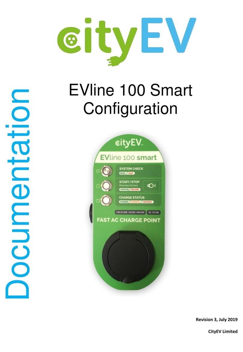
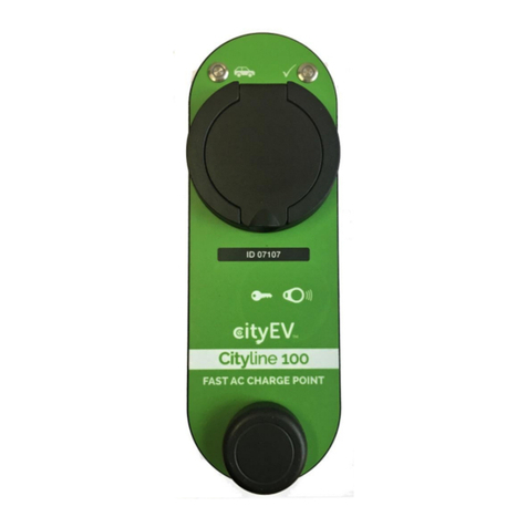
CityEV Cityline 100 User manual

Revision 1.
4
,
May
202
2
Copyright © 2022
CityEV Limited
All Rights Reserved. All trademarks are
owned CityEV Limited
Cityline 100
EVline 100
Installation and User
Manual

Page 2
Warranty 3
About Your System 3
Important Safety Information 3
The Cityline 100 Fast AC Chargepoint 5
Installation 6
Front panel removal 6
Post Mount Installation 7
Mechanical Installation 8
Mounting the Chargepoint 9
Wall Mount Installation 10
Mechanical Installation 11
Mounting the Chargepoint 12
Supply Connections 13
Safevolt Function 16
Safevolt Modes 16
Installing the earth Sense probe (required if using Safevolt mode 2) 16
Sense Probe Cable 17
Earthing Precautions 18
Reference Installation Schematics 19
Local Chargepoint Configuration 22
Available Configuration Parameter Options 23
Configuration Programming Method 24
Cityline 100 Operation 28
Panel Indicators 28
Cityline 100 Indicator LED Functions 29
Vehicle Charging procedure 31
NFC / QR Label Application 32
Chargepoint Measurements and Reporting 33
Declaration of Conformity 34
Contents

Page 3
Warranty
UNLESS SPECIFICALLY AGREED TO IN WRITING, SELLER
(A) MAKES NO WARRANTY AS TO THE ACCURACY, SUFFICIENCY OR SUITABILITY OF ANY
TECHNICAL OR OTHER INFORMATION PROVIDED IN ITS MANUALS OR OTHER DOCUMENTATION.
(B) ASSUMES NO RESPONSIBILITY OR LIABILITY FOR LOSSES, DAMAGES, COSTS OR EXPENSES,
WHETHER SPECIAL, DIRECT, INDIRECT, CONSEQUENTIAL, OR INCIDENTAL, WHICH MIGHT ARISE
OUT OF THE USE OF SUCH INFORMATION. THE USE OF ANY SUCH INFORMATION WILL BE
ENTIRELY AT THE USER’S RISK; AND
(C) REMINDS YOU THAT IF THIS MANUAL IS IN ANY LANGUAGE OTHER THAN ENGLISH,
ALTHOUGH STEPS HAVE BEEN TAKEN TO MAINTAIN THE ACCURACY OF THE TRANSLATION, THE
ACCURACY CANNOT BE GUARANTEED. APPROVED CONTENT IS CONTAINED WITH THE ENGLISH
LANGUAGE VERSION WHICH IS POSTED AT WWW.CITYEV.NET
Revision: 1.2 Date: June 2020
Product Part Number: Cityline 100
About Your System
As soon as you open your product, record the following information and be sure to keep your
proof of purchase.
Serial Number
Product Number
Purchased From
Purchase Date
Important Safety Information
Warning conventions used in this manual
⚠ DANGER indicates an imminently hazardous situation which if not avoided will
result in death or serious injury.
⚠ WARNING indicates a potentially hazardous situation which, if not avoided, can
result in death or serious injury.
⚠ CAUTION indicates a potentially hazardous condition.
All safety warnings give specific details of the potential danger/warning present
and indicate how to reduce risk of injury, damage and electric shock resulting from
improper use of the device.
Important Safety Information

Page 4
Carefully observe the following instructions:
• Installation and maintenance must be carried out by a competent person, in
compliance with the manufacturer's instructions, the relevant wiring regulations
and local safety regulations.
If in any doubt, consult a qualified electrician.
• The device must be disconnected from the power supply before carrying out
any installation or service work.
• Do not remove the device cover while the power supply is connected.
• Do not operate the device with the cover removed.
• Do not attempt to repair or replace any part of the device. In case of
malfunction contact your installer or CityEV Ltd.
• All maintenance operations must be carried out by a qualified technician.
• The manufacturer accepts no responsibility for any damage or injury caused by
improper use or failure to comply with these instructions.
⚠ Failure to follow these instructions can result in death or serious injury.
Important Safety Information

Page 5
Introduction
The Cityline 100 Fast AC Chargepoint
The Cityline 100 Smart Electric Vehicle Supply Equipment (EVSE)EVSE unit is a single
phase smart EV charge point which can provide a maximum of 8KW (32A per
phase).
The maximum charge rate is programmable from 1.4KW to 8KW (6A to 32A) to
allow adaption to local supply availability.
The Cityline 100 can be managed by a central system and offers operators a choice
of access methods, with our mobile app, fob operation or free-to-use modes.
Designed for fast and economical roll-out for new and existing networks; the unit is
capable of centralised dynamic load management and offers the possibility for load
balancing, where the charge station controls the power offered per socket
according to demand.
The Cityline 100 charge point has built-in CityEV Safevolt® technology which
provides protection in the event of a Protective Multiple Earthing (PME) PME
earthing failure and enables the Cityline 100 to be safely installed on a PME system
and be fully compliant with BS7671 18th edition amendment 1.
In addition to PEN conductor failure detection and isolation under fault conditions,
the Cityline 100 also monitors DC leakage current. This function is equivalent to a
‘type B’ RCD and will trip and isolate the charge point if a DC leakage current
greater than 6mA is detected. This allows the charge point supply circuit to be
protected with a standard ‘type A’ RCD and eliminates the need to provide a costly
‘type B’ RCD device.
Cityline 100 Installation Manual

Page 6
Installation
The Cityline charge point can be either post mounted or wall mounted.
Guidance is given below for both mounting methods.
The charge point consists of two main components, the front panel which houses
all the electronics, and the weatherproof back shell.
To install the charge point first remove the front panel from the back shell.
Front panel removal
To remove the charge point front and electronics from the back shell, unscrew the
four security screws on the charge point side. The front can then be pulled off the
back shell.
Tip: For easy removal of the charge point front, once the four screws are removed,
insert a type 2 plug into the charging socket and apply a gentle sideways force to
the connector.
Cityline 100 Installation Manual

Page 7
Post Mount Installation
The Cityline 100 can be mounted to the following standard column sizes using the appropriate CityEV post
mount brackets:
76mm, 89mm, 114mm, 140mm, 168mm
For a standard column mount installation, the following tools and consumables will be needed:
* Only available for 76mm, 89mm, 114mm post sizes
Cityline 100 Installation Manual
Cityline 100 Installation Manual
Post mount bracket to suit
column size
M6 Crimp Nut x 2
M6 x 20 button head hex
screw x 2
Crimp Nut
insertion
tool
20mm hole saw
or step drill
9mm Drill Bit
5mm Drill Bit
Power Drill
CityEV
Post Mount
Jig*
Security Driver Bits
TORX T20
Snake Eye 8/TH5
Cityline 100 Installation Manual

Page 8
Mechanical Installation
To comply with IET regulations the charge point should be installed with the charging socket positioned
between 0.75M and 1.4M from the ground.
The chargepoint is attached to the post using the CityEV post
mount bracket.
Cityline 100 Installation Manual
Max 1400mm
Min 750mm
Post
Bracket
Chargepoint

Page 9
Mounting the Chargepoint
Cityline 100 Installation Manual
1. Position the drill jig in the desired
position and drill 3 x 5mm pilot holes in
the post.
2. Drill out the top pilot hole to 20mm for
the cable access.
3. Drill out the two lower holes to 9mm for
the M6 crimp nuts
4. Insert the crimp nuts using the insertion
tool.
5. Attach post mount to post with 2 x M6 x
20 button head screws.
6. Attach charge point back shell to post
bracket using the 4 x M4 x 8 screws
and fibre washers provided.
1
2/3/4
5
6

Page 10
Wall Mount Installation
The Cityline 100 can be mounted to any suitable flat surface using the CityEV wall plate adaptor.
The following tools and consumables will be needed:
Cityline 100 Installation Manual
Wall mount plate 4 x suitable wall fixings
6mm Masonry Drill Bit
Power Drill
Security Driver Bits
TORX T20
Snake Eye 8/TH5

Page 11
Mechanical Installation
To comply with IET regulations the charge point should be installed with the charging socket positioned
between 0.75M and 1.4M from the ground.
The chargepoint is attached to the wall using the CityEV wall
mounting plate
Cityline 100 Installation Manual
Max 1400mm
Min 750mm
Wall
Chargepoint
Cityline 100 Installation Manual
Mounting
plate

Page 12
Mounting the Chargepoint
Decide on the supply cable entry position.
This can either from the rear of the charge point, through the wall and mounting plate
Or
Via a conduit from the bottom of the charge point
If cable access will be from the rear of the charge point, create the cable access through the wall
bearing in mind that this will line up with the large hole in the top of the mounting plate.
1. Mount the wall plate using 4 off suitable
fixings
2. Attach charge point back shell to post
bracket using the 4 off M4 x 8 screws
and fibre washers provided.
1
2
Cityline 100 Installation Manual

Page 13
Supply Connections
Install the supply tails into the back shell via the rear or bottom cable gland.
For 16A/20A supply and 16A charge point use 4.0mm cable.
For 32A/40A supply and 32A charge point use 6mm cable.
The supply connection points are lever operated terminals which can accept up to 6mm2 cables.
The supply connection points are shown below:
Standard Built-in Meter Version [ Note see reference installation schematic on pages 19 & 20 ]
Cityline 100 Installation Manual
Live Input
Neutral Input
Column, Lamp &
EV via Safevolt:
> Case Earth
> Earth OUT
-------------------------
Column & Lamp
on PME, EV via
Safevolt:
> Not Used
Safevolt probe connection
Column, Lamp &
EV via Safevolt:
> PME Earth IN
-------------------------
Column & Lamp
on PME, EV via
Safevolt:
> PME Earth IN
> Case Earth

Page 14
MID Approved Meter Version [ Note see reference installation schematic on pages 19 & 20 ]
Important Note
This chargepoint utilises high currents and incorrectly terminated supply connections
Can result in damage due to excessive heat build-up.
When connecting the live and neutral to the incoming meter terminals
ensure that the terminal is fully undone before inserting the wire
and that the wire is not underneath the clamp.
Securely tighten the terminal to a torque of 1.5Nm.
If using stranded wire, a bootlace ferrule must be used.
Cityline 100 Installation Manual
Live Input
Neutral Input
Safevolt probe connection
Column, Lamp &
EV via Safevolt:
> Case Earth
> Earth OUT
-------------------------
Column & Lamp
on PME, EV via
Safevolt:
> Not Used
Column, Lamp &
EV via Safevolt:
> Case Earth
> Earth OUT
-------------------------
Column & Lamp
on PME, EV via
Safevolt:
> PME Earth In

Page 15
1. Once the supply cables are connected, connect the GSM antenna cable to the SMA connector on
the top of the circuit board.
2. Re attach the front panel by offering the bottom of the panel first to the back shell.
Slide the panel down until the bottom flat on the panel engages with the bottom flat on the back
shell. Then push the top of the panel home and hold in position while inserting a security screw
into the side of the back shell.
Insert all 4 screws loosely first and then tighten all 4 screws. The front panel will seal as
the screws are tightened. Do not over tighten.
Attaching the Front Panel Security screw in place
GSM Antenna Connection
Cityline 100 Installation Manual
Cityline 100 Installation Manual

Page 16
Safevolt Function
The Cityline 100 charge point has built-in CityEV Safevolt® technology which provides protection in the
event of a PME earthing failure and enables the Cityline 100 to be safely installed on a PME system and be
fully compliant with BS7671 18th edition amendment 1.
The 18th edition and the IET code of practice introduces strict conditions for electrical installations of
charge points on PME single and three phase installations.
The CityEV Safevolt® technology removes the need for costly and disruptive site works such as installing
ground rods or impractical isolation transformers.
Safevolt Modes
The Safevolt function can be configured to operate in two different modes.
Mode 1 – (factory default) Uses a line voltage sensing method to determine if a PEN conductor
(PME) failure has occurred.
This method provides compliance with BS7671:2020 18th Edition, amendment 1, 722.411.4.1.(iv)
No earth sensing probe is required for operation in this mode.
Mode 2 – Uses a small micro probe which is installed in contact with the ground.
Note: Not normally used for single phase chargepoints
The probe continually measures the touch voltage between true earth and the PME earth and
initiates a trip if the PME voltage rises to a dangerous level with respect to true earth due to a
PEN conductor failure.
This method provides compliance with BS7671:2020 18th Edition, amendment 1, 722.411.4.1.(iii)
This mode requires the earth sense probe to be installed.
Installing the earth Sense probe (required if using Safevolt mode 2)
The optional 300mm stainless steel earth touch voltage sense probe will be required.
The probe can be installed in any convenient location where access to soil can be found, however
note that the probe must be positioned at least 2M from any metallic object, pipe or
unsheathed cable which is connected to the PME earth.
⚠Failure to observe this may result in a reduction in the sensed touch voltage under a PME fault
condition which would reduce the effectiveness of the system.
Cityline 100 Installation Manual

Page 17
Sense Probe Cable
The cable which connects the earth sense probe is classed under BS7671 as a "Functional Earth” i.e., not a
safety earth connection and therefore the colour of the cable connecting the probe to the Safevolt unit:
Must not be Green/Yellow which is used for safely earth connections
In BS7671 the colour specified for a functional earth is cream or pink.
Sense Probe Cable Sizing
The current carried by the sense probe is very small as the probe input of the unit is high impendence.
From an electrical standpoint therefore, the cable could be a very small CSA.
However, consideration should be given to mechanical protection of the cable depending on the location
of the cable run etc. A larger size of cable may be needed, or the cable may need to be run in a conduit
depending on the level of exposure / protection for the installation.
The sense probe is connected via a 2
-
pin connector
located at the bottom of the main PCB, The probe is
connected to the pin marked “Probe” (Left hand
connection).
The charge point is delivered with a link installed
between the two pins of this connector. With this link
installed the mode 2 Safevolt function is disabled.
Note Safevolt mode 1 will operate regardless of the
presence of a link on this connector.
Sense Probe Connection
Cityline 100 Installation Manual
Cityline 100 Installation Manual

Page 18
Sense Probe Performance
Because the measurement system is high impendence the system can work with a
"very poor" earth probe connection; The earth probe connection impendence can be up to
120K Ohms and still operate reliably. This will allow the probe to be installed in many situations which
would be unsuitable for a safety earth TT connection.
There is no requirement to perform any measurements on the earth probe during installation as the
Safevolt unit itself can determine if the installation is adequate.
The Safevolt continually monitors the suitability of the probe connection and determines if the sense
probe connection earth is adequate. If the earth sense probe connection is not suitable the middle LED
will flash continually the charge point output will be disabled.
Earthing Precautions
The Safevolt function is designed to isolate the installation CPC from the charge point CPC in the
event of a PEN conductor (PME) failure.
⚠ It is therefore important to check that no part of the charge point casing is connected to any
point which is directly or indirectly connected back to the building earth.
Any such connections will render the Safevolt system ineffective.
Cityline 100 Installation Manual

Page 19
Reference Installation Schematics
The schematic below shows the typical installation arrangement for the Cityline 100 installation.
Points to note:
For 3.5KW installations use a 20A 2 pole Type A RCD, 20A MCB and 4mm cable.
For 7.2KW installations use a 40A 2 pole Type A RCD, 40A MCB and 6mm cable.
The RCD, MCB and Chargepoint must be installed on a dedicated circuit.
Multiple charge points installed at the same location can use a single sense probe.
No supply diversification is allowed for multiple charge points.
Supply
L
N
E
Cut
-
Out
2 pole 30mA
Type A
RCD*
Lamp
Supply
6A MCB
20A MCB*
Chargepoint
Column
Incoming PME Earth
Protected
Earth Out
PME
Earth In
* Alternatively, a 20A double
pole RCBO can be used
E
-
IN
E
-
OUT
E
-
IN
E
-
IN
Column, Lamp & EV Earth via Safevolt

Page 20
Cityline 100 Installation Manual
Supply
L
N
E
Cut
-
Out
2 pole 30mA
Type A
RCD*
Lamp
Supply
6A MCB
20A MCB*
Chargepoint
Column
Incoming PME Earth
PME
Earth In
* Alternatively, a 20A double
pole RCBO can be used
E
-
IN
E
-
OUT
E
-
IN
E
-
IN
Column & Lamp on PME Earth, EV Earth via Safevolt
(Not Used)
This manual suits for next models
1
Table of contents
Other CityEV Batteries Charger manuals
