IES Keywatt 50 Series User manual

User Manual
Keywa 50 Staon Bus
www.ies-synergy.com
DUM017749-EN_V001b

www.ies-synergy.com
User Manual DUM017749-EN
2
The information provided in this documentation contains general descriptions and/or technical characteristics
of the performance of the products contained herein. This documentation is not intended as a substitute for
and is not to be used for determining suitability or reliability of these products for specific user applications. It
is the duty of any such user or integrator to perform the appropriate and complete risk analysis, evaluation and
testing of the products with respect to the relevant specific application or use thereof. Neither IES Synergy nor
any of its affiliates or subsidiaries shall be responsible or liable for misuse of the information contained herein.
If you have any suggestions for improvements or amendments or have found errors in this publication, please
notify us.
You agree not to reproduce, other than for your own personal, noncommercial use, all or part of this document
on any medium whatsoever without permission of IES Synergy, given in writing. You also agree not to establish
any hypertext links to this document or its content. IES Synergy does not grant any right or license for the per-
sonal and noncommercial use of the document or its content, except for a non-exclusive license to consult it on
an “as is” basis, at your own risk. All other rights are reserved.
All pertinent state, regional, and local safety regulations must be observed when installing and using this prod-
uct. For reasons of safety and to help ensure compliance with documented system data, only the manufacturer
should perform repairs to components.
When devices are used for applications with technical safety requirements, the relevant instructions must be
followed.
Failure to use IES Synergy software or approved software with our hardware products may result in injury,
harm, or improper operating results.
Failure to observe this information can result in injury or equipment damage.
© 2020 IES Synergy. All rights reserved.

www.ies-synergy.com
User Manual DUM017749-EN
3
Table of content
1. Safety notes 4
Notice 4
Please note 4
2. About the manual 5
Purpose of this manual 5
Document scope 5
Related documents 5
User comments 5
3. General Safety instructions 6
4. Overview 7
External view 7
5. Specification 8
Main supply 8
3-phase L1/L2/L3 + N + GND (3x400VAC) 8
Technical specification 8
Compliance 10
Derating 10
6. Utilization 12
Human/Machine interface (HMI) 12
Lights 12
Start a charge session 12
EV communication 13
EV charge 13
Stop a charge session 14
Emergency Stop 14
7. Displayed messages 15
Error messages 15
Other messages 16
8. Cleaning 17

www.ies-synergy.com
User Manual DUM017749-EN
4
1. Safety notes
Notice
Read these instructions carefully, and look at the equipment to become familiar with the device before trying
to install, operate, or maintain it. The following special messages may appear throughout this documentation
or on the equipment to warn of potential hazards or to call attention to information that clarifies or simplifies
a procedure.
The addition of this symbol to a Danger hazard statements indicates that an electrical hazard
exists, wich result in personal injury if the instructions are not followed.
This is the safety alert symbol. It is used to alert you to potential personnal injury hazards. Obey
all safety messages that follow this symbol to avoid possible injury or death.
IDANGER
DANGER indicates an imminently hazardous situation which, if not avoided, will result in death or seri-
ous injury.
IWARNING
WARNING indicates a potentially hazardous situation which, if not avoided, can result in death or seri-
ous injury.
ICAUTION
CAUTION indicates a potentially hazardous situation which, if not avoided, can result in minor or mod-
erate injury.
NOTICE
NOTICE is used to address practices not related to physical injury.
Please note
No responsibility is assumed by IES Synergy for any consequences arising out of the use of this material.

www.ies-synergy.com
User Manual DUM017749-EN
5
2. About the manual
Purpose of this manual
Technical documentation is an integral part of a product. Until it is disposed of, always keep the technical docu-
mentation close to the unit at hand, as it contains important information. Provide technical documentation to
the person concerned if you sell, assign or lend the product.
This guide aims to provide informations needed for the use of the Keywatt 50 Station Bus. This guide must be
read with other related documents. This guide is intended for users of the charging stations.
Document scope
This guide concerns the following charging station:
• P/N: 50kW CHARGING STATION
Related documents
Document title Reference
Installation Manual DIM017749-EN
User Manual DUM017749-EN
Service Manual DMM017749-EN
User comments
We invite you to write to us to communicate any inaccuracies or omissions, or to make general comments or
suggestions regarding the quality of this manual.

www.ies-synergy.com
User Manual DUM017749-EN
6
3. General Safety instructions
NOTICE
SAVE THESE INSTRUCTIONS
• To ensure proper and safe operation, please read these user instructions carefully and
keep them for future reference.
• This manual contains important instructions for STATION 50kW for TT, TN and IT earng
systems that shall be followed during installation, operation and maintenance of the unit.
• The locking key, supplied with unit, should be kept in a secure and known location by an
individual that has read and understands the content of this manual.
IWARNING
RISK OF ELECTRIC SHOCK, INJURY, AND/OR BURNING
• Only qualified, trained and authorized people will repair, replace or adjust this equipment.
• Make sure the AC input breaker is OFF and measures 0V before the breaker.
• Disconnect the protective device located upstream of the charger before working on it.
• Do not use this product if the cables (input or output) are frayed, have damaged insulation
or any other signs of damage.
• Do not use this product if the enclosure or the EV connectors are broken, cracked, opened
or show any other indication of damage.
• Replace the damaged cables by same caracteristics cables.
• Do not use a cord extension set, second cable assembly or adaptors in addition to the
cable assembly for the connection of the EV to the EVSE.
• Do not alter AC plug provided – where it does not fit outlet, have proper outlet installed
by a qualified electrician. Improper connection increases the risk of an electric shock.
• Charger shall be grounded to reduce risk of electric shock. Charger is equipped with an
electric cord having an equipment-grounding conductor and a grounding plug. The plug is to
be plugged into an outlet that is properly installed and grounded in accordance with all local
codes and ordinances.
• This unit is for use on a circuit having a nominal rating more than 120V and is factory-
equipped with a specific electric cord and plug that connects to an electric circuit. Make
sure that the charger is connected to an outlet having the same configuration as the plug.
Adapters shall not be used with this charger.
• This equipment employs parts, such as switches and relays, that tend to produce arcs or
sparks.
• Never open the charger while input power is present.
Failure to follow these instructions can result in death or serious injury
www.ies-synergy.com
User Manual DUM017749-EN
7
4. Overview
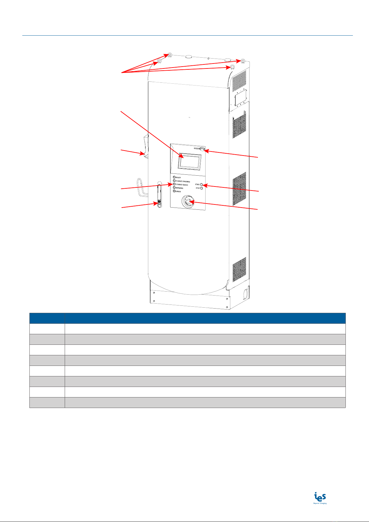
External view
READY
CHARGE ONGOING
CHARGE ENDED
WARNING
ERROR
START
STOP
❶
❻
❷
❸
❺
❹❼
❽
Position Description
❶Lifting rings
❷Touch screen
❸Connector holster (in option)
❹State of charge
❺Door lock
❻RJ45 input (for maintenance only)
❼Power button (START/STOP)
❽Emergency Stop button
Note: May change depending on version or technical modification

www.ies-synergy.com
User Manual DUM017749-EN
8
5. Specification
Main supply
3-phase L1/L2/L3 + N + GND (3x400VAC)
The charging station can be connected to several mains supplies. This table shows the main power supply char-
acteristics required for the following Station configuration operation:
• P/N: 50kW CHARGING STATION
Mains supplies 3-phase L1/L2/L3 + N + GND (3x400VAC) (50kW)
Mains 3-phase voltage range VAC 400 VAC ± 10%
Earthed electrical system TT, TN or IT
Assigned frequency f 50 Hz +4%/-6%
Maximum input current per phase IINmax 80A Max
Power Factor PF 0,99 Nom
Efficiency
(@ VIN : 400VAC / VOUT : 800V / IOUT : 62.5A / POUT : 49.6kW) ɳ95 % Max
Harmonic current @ nominal network voltage THDi < 16 % (@ Pout > 0,3 Pmax)Max
Technical specification
Internal AC input protection
Inrush current limitation per phase IINRUSH LIMIT < 3 x IAC Max
Rated current circuit breaker IBREAK Rating 100A typ
Rated short-circuit capacity IBREAK Capacity 15 kA Max
Max earth leakage current ILEAKAGE < 3,5 mA Max
Emergency button connection Yes
Overvoltage category III
Internal DC Output
Output voltage VDC_max 800 VDC Max
VDC_min 400 VDC Min
Output current IDC_max 75A (1)(2) Max
IDC_min 5A Min
Max Output Power POUT 50kW Max
Output connector (charging station side) Permanent mounting
Car Plug connector IEC CCS Combo 2
Output cable length Meters 4m or 7m in option
Internal DC output protection
Hardware and software short circuit protection Yes
Software and Hardware over voltage protection adjustable +10% max
Over temperature protection - 70°C
Reverse polarity protection Yes
DC output Contactor Yes (2 poles)
Rated Current Fuse (output) IFUSE 175 A
Galvanic isolation Vinput / output 2520 VDC
Max time for DC line discharge < 60V T<60V 1 s
www.ies-synergy.com
User Manual DUM017749-EN
9
Radio Frequency characteristics
The equipment module is designed to provide customers with global network coverage on the connec-
tivity of UMTS/HSPA+, and it is also fully backward compatible with the existing EDGE and GSM/GPRS
networks.
Output power (dBm)
Class 4 (33dBm±2dB) for GSM850 and EGSM900
Class 1 (30dBm±2dB) for DCS1800 and PCS1900
Class E2 (27dBm±3dB) for GSM850 and EGSM900 8-PSK
Class E2 (26dBm+3/-4dB) for DCS1800 and PCS1900 8-PSK
Class 3 (24dBm+1/-3dB) for UMTS800/850/900/1900/2100
General & dimensions
External dimensions without gun holder (HxWxD) mm 2010 x 710 x 510 mm
External dimensions with gun holder (HxWxD) mm 2010 x 820 x 510 mm
Weight (with DC cable and cable management) Kg 320kg Max
Type of installation Indoor / outdoor (but not public area)
Fixation points 4 studs M14 for ground mounng
Mechanical resistance to impact IK IK10 (except screen IK09)
Protection Type (EN60529) IP IP55
Cooling system Heatsink with forced air flow by fans IP55 without
air filter
Acoustic level (1m, all directions) Db(A) 58.9 dbA (1m)
Climatic & Environment constraints
Operating temperature (with derating) -25°C to +50°C(3)
Storage temperature -25°C to +70°C
Relative humidity RH 5% to 95%
Installation altitude Alt Max 2 000 m
Norms & standards
Radio Equipment Direcve (RED) 2014/53/EU (4)
Efficient use of Radio Spectrum (RED)
ETSI EN 301 511 V12.5.1
ETSI EN 301 908-1 & -2
V11.1.1
ETSI EN 300 330 v2.1.1
Informaon technology equipment - Safety - Part 1: General requirements IEC 60950-1:2005 (A1:2009
+ A2:2013)
Informaon technology equipment - Safety - Part 22: Equipment to be
installed outdoors IEC 60950-22:2016
Electrical safety in low voltage distribuon systems up to 1000 VAC and
1500 VDC - Equipment for tesng, measuring or monitoring of protecve
measures - Part 8: Insulaon monitoring devices for IT systems
IEC 61557-8 (4)
Electric vehicle conducve charging system - Part 1: General requirement IEC 61851-1 (4)
Electric vehicle conducve charging system - Part 21-2: Electric vehicle
requirements for conducve connecon to an AC/DC supply EMC
requirements for o-board electric vehicle charging systems
IEC 61851-21-2 (4)
Electric vehicle conducve charging system - Part 23: DC Electric vehicle
charging staon IEC 61851-23 (4)

www.ies-synergy.com
User Manual DUM017749-EN
10
Norms & standards
Electric vehicle conducve charging system - Part 24: Digital
communicaon between a DC EV charging staon and an electric vehicle
for control of DC charging
IEC 61851-24 (4)
Charge Communicaon systems Standards ISO/IEC 15118
OCPP design rules 010-030-007 Rev1.6
Digital communicaon between a DC EV charging staon and an electric
vehicle for control of DC charging in the Combined Charging System DIN 70121
Vibraon and shock resistance
STD ASTM D 4169-16
STD ASTM D 880-92
STD ASTM D 4728-17
STD ASTM D 6055-96
STD ASTM D 6179-07
(1) Max output current will be adapted versus maximum carrying current of the vehicle plug
(2) Output current can be even reduced with the power derang versus temperature.
(3) With derang above 30°C
(4) Design in compliance with CE direcves
Compliance
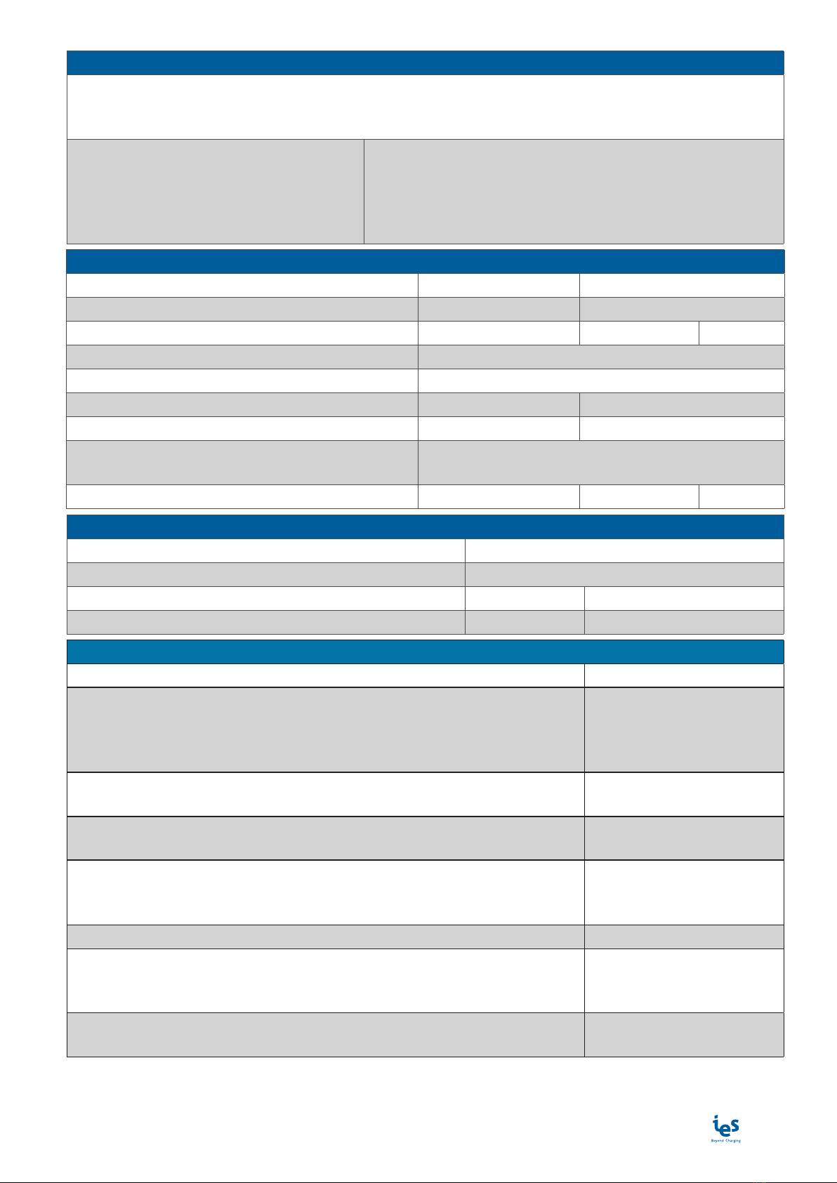
Derating
As a direct correlation exists between the output power and the ambient temperature a derating curve is pro-
vided for all charging station.
www.ies-synergy.com
User Manual DUM017749-EN
11
www.ies-synergy.com
User Manual DUM017749-EN
12
6. Utilization
Human/Machine interface (HMI)
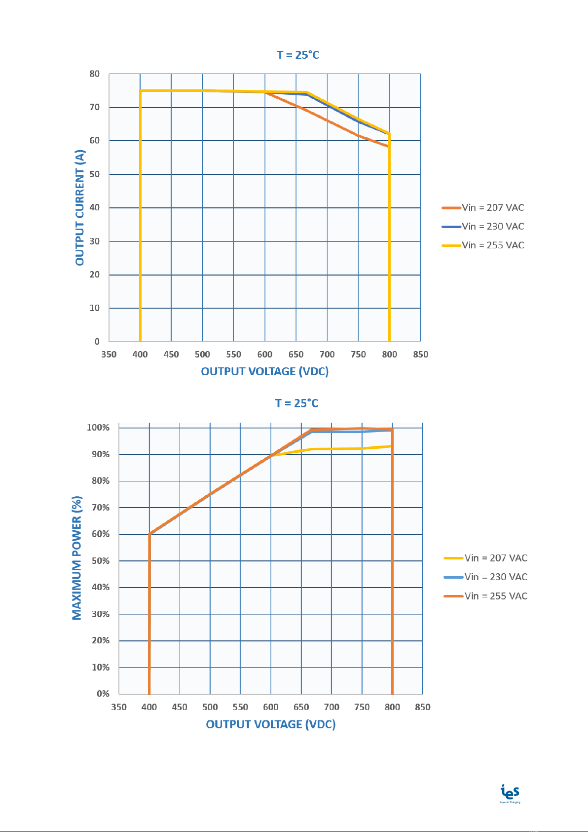
Lights
Charger ready CCS connected Charging Charge ended Warning Error
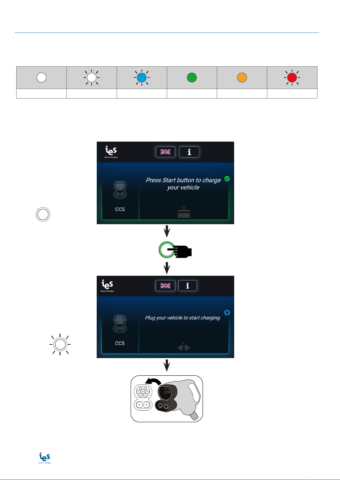
Start a charge session
Before starting a charge session, ensure the unit is properly assembled in accordance with the assembly in-
structions being used.
READY
START
f = 0.5 Hz READY
www.ies-synergy.com
User Manual DUM017749-EN
13
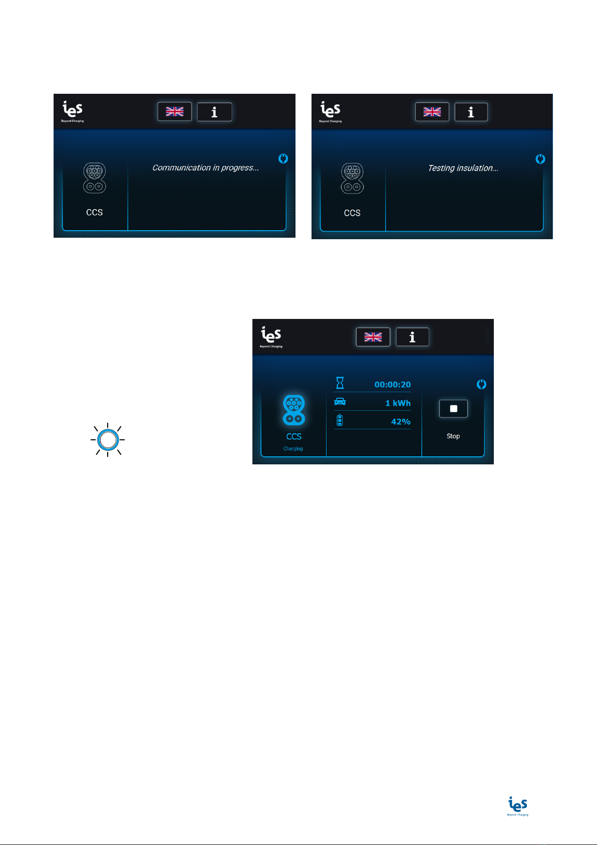
EV communication
Before starting a charge, the charging station communicates with the electrical vehicle to collect information.
All these steps are necessary to adapt the charging station parameters to the EV.
→
EV charge
While the EV is charging, the charging station shows the information about the charge (time since the start of
charging, charged energy and percentage of charge).
f = 0.5 Hz CHARGE ONGOING

www.ies-synergy.com
User Manual DUM017749-EN
14
Stop a charge session
The charger will automatically stop once charging is completed. Fast charging will occur up to 80% of the
vehicle battery state of charge. The charger will adjust its output according to the demands of the vehicle,
ambient temperature and other factors.
To stop the charge before the end of the EV charge:
STOP
CHARGE ENDED
Emergency Stop
In the event of an emergency the Emergency Stop button may be pressed to instantly stop charging.
To emergency stop follow these steps:
1. Press the emergency stop button bellow the charger
2. The display will show the text “Error ocurred: 0x02 Emergency stop was launched. Please unplug your vehi-
cle and check that the emergency button is released.”
3. Unplug the connector from the vehicle
To reset after an emergency stop, rotate the button clockwise until it pops outward. After a self-test, the display
will remove the emergency stop message and will be ready for a new session.
www.ies-synergy.com
User Manual DUM017749-EN
15
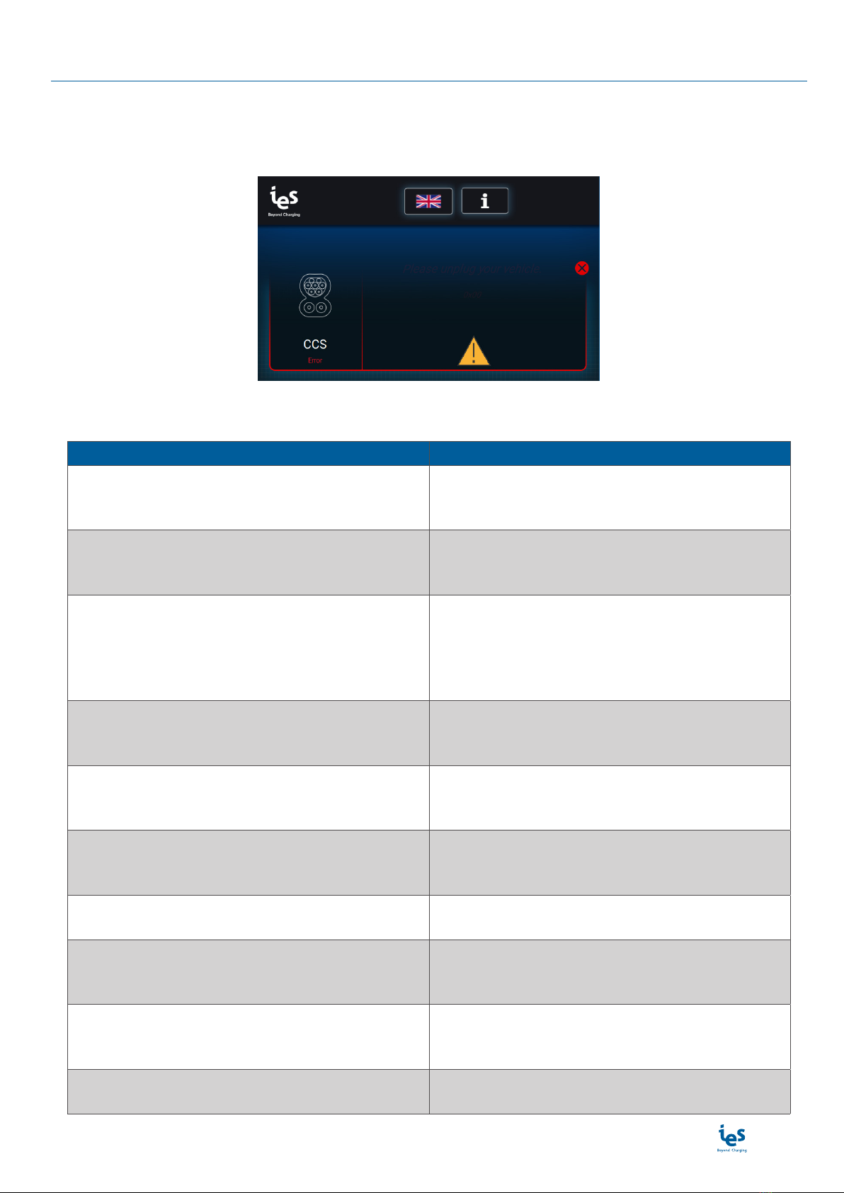
7. Displayed messages
Error messages
The error messages are displayed with a characteristic screen. They are thus easily identifiable by the user. A
warning pictogram is displayed along with the error message as shown below.
The table below list errors messages who appears on the screen.
Error Error resolution
Error occurred: 0x02 - 0X03 - 0X81
Emergency stop. Please unplug your vehicle and re-
lease the emergency button.
Emergency stop was initiated. Please unplug your
vehicle and release the emergency button.
Error occurred: 0x02 - 0X03 - 0X81
Emergency stop. Please unplug your vehicle and re-
lease the emergency button.
Emergency stop was initiated. Please unplug your
vehicle and release the emergency button.
Error occurred: 0x22 - 0x33
The connector cannot lock. Please keep the con-
nector closely leant against your vehicle when
plugging, until the charge has started. Please un-
plug your vehicle.
The connector cannot lock. Please keep the con-
nector closely leant against your vehicle when
plugging, until the charge has started. Please un-
plug your vehicle.
Error occurred: 0x3A
Your battery model is incompatible with this char-
ger. Please unplug your vehicle.
Your battery model is incompatible with this char-
ger. Please unplug your vehicle.
Error occurred: 0x31
Your battery’s temperature is too high. Please un-
plug your vehicle.
Your battery’s temperature is too high. Please un-
plug your vehicle.
Error occurred: 0x46
Connection between screen and charger has been
lost. Please unplug your vehicle.
Connection between HMI screen and charger has
been lost. Please unplug your vehicle.
Error occurred: 0x--
Please unplug your vehicle.
For all other error codes, please refer to mainte-
nance manual.
Error connecting server.
Booting interrupted !
Please call support.
Message displayed during the startup of the
charging station if the backend server reject the
connection.
Error connecting to Communication Control Unit.
Booting interrupted !
Please call support.
Message displayed during the startup of the
charging station if the CCU board does not work.
Please contact support.
Error timeout. Please unplug your vehicle then
identify.
Time out, user identified, unplug the vehicle before
retrying to identify.
www.ies-synergy.com
User Manual DUM017749-EN
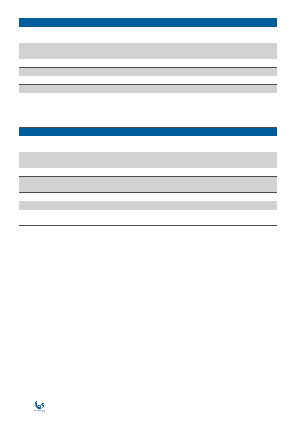
16
Error Error resolution
Error: Authorization failed.
You cannot stop the charge session.
The charge cannot be interrupted by this user who
is not recognized by the backend server.
Error updating. DO NOT CHARGE HERE. Wait for
correct update.
Error updating. Please contact support for updating
the charging station.
Warning: insulation failure. Cable insulation failed. Please contact support.
0x1B: ERR_Insulation_Measure_Failure Insulation measure failure.
0x88: ERR_PSU_Insulation_Fault PSU insulation fault.
0x8C: ERR_PSU_INS_CONTROLLER_FAILED PSU insulation controller failed.
Other messages
When the following messages are displayed on the charging station’s screen, the charge is unavailable.
Message Description
Charger inoperative. Cannot charge here. Charger inoperative. Backend server request char-
ger does not accept charge
Charger inoperative. Please unplug your vehicle. Charger inoperative. Backend server request char-
ger does not accept charge. Unplug the vehicle.
Charger offline. Set up to refuse offline charging. Charger offline.
Station shut down. Please reboot. Charging station shut down. Please contact support
to restart the charging station.
Updating station... Charging not available. Charging station is being updated. Please wait.
Remote reset started... Station will reboot now. Station is being rebooted.
Station rebooted. Please unplug your vehicle. Station rebooted during a charge. Please unplug
and retry to launch the charge.

www.ies-synergy.com
User Manual DUM017749-EN
17
8. Cleaning
ICAUTION
RISK OF DAMAGE TO THE TERMINAL
• DO NOT use a high pressure jet to clean the device.
• Preserve the terminal from contact with gasoline, diesel and other automotive fluids.
• DO NOT use solvents to clean the terminal.
Failure to follow these instructions can cause damage.
IWARNING
HAZARD OF ELECTRIC SHOCK, EXPLOSION, OR ARC FLASH
• To avoid danger of electrical shock or injury, turn off power at the panel board or load
center before working on the equipment or removing any component. Do not remove circuit
protective devices or any other component until the power is turned off.
• Disconnect electrical power to the harging station before any maintenance work to ensure
that it is separated from the supply of AC mains. Failure to do so may cause physical injury or
damage to the electrical system and charging unit.
• Maintenance of the charging station shall be conducted only by a qualified technician.
Failure to follow these instructions can result in death or serious injury.
Cleaning the charger is only made with a dry cloth, twice a year, charger OFF and not connected.
Every six months,
• Conduct a visual inspection of the air inlet of the charging station and ensure that they are not clogged.
• Conduct a visual inspection of the charging cable and ensure that cable does not show any visual damage
or deformation.
• Conduct a visual inspection of the charging gun and ensure that gun does not show any visual damage,
arcing or rust.
Every year, conduct a visual inspection of the state of the lightning protections and ensure that they are not
damages.

www.ies-synergy.com
User Manual DUM017749-EN
18
Notes

www.ies-synergy.com
User Manual DUM017749-EN
19
Notes

As standards, specicaons, and designs change from me to me, please
ask for conrmaon of the informaon given in this publicaon.
IES Synergy (Head Oce) IES GmbH (North Europe)
615, Avenue de la Marjolaine Bergfeldstr. 11
34130 Saint Aunès 83607 Holzkirchen
France Germany
Tel: +33 (0)4 99 13 62 80 Tel: +49(0)80244633980
Fax: +33 (0)4 99 13 62 81
IES-Synergy Inc. (USA) IES WANMA New Energy (China)
330 East Maple Rd Building No 4, Wellong Technology Park
Unit U No. 88 Jiang Lin Rd
MI43084 Troy Binjiang Hangzhou
USA Zhejiang 310051
Tel: +1 (586)206-4410 China
Tel: +8657189877710
www.ies-synergy.com
DUM017749-EN_V001b
June 2020
Other manuals for Keywatt 50 Series
1
Table of contents
Other IES Batteries Charger manuals


Popular Batteries Charger manuals by other brands


Festool
Festool MCU 15 Original operating manual/spare parts list

NOCO Genius
NOCO Genius GENIUS2JP User guide & warranty

DeWalt
DeWalt DCB118X2 Original instructions

Intermec
Intermec Janus 2020 Quick reference guide

Radio Shack
Radio Shack 23-348 owner's manual

Siemens
Siemens SICHARGE 8EM4110 Series operating instructions


