Clank Chaos User manual
Chaos manual // v 1.1

2
The concept
What is Chaos for real? Chaos is the hidden force that moves everything around us. It’s a random stream of
events, whose correlation is impossible to understand. Even if its presence is a living paradox in our life, we are
used to inuence chaos in a very deterministic way by setting the limits of its dynamic behavior: in this way we
can predict events and make them possible.
We can set steady points, enclose them into cycling loops and then make them work for us as laws. That’s exactly
what our Chaos does. A continuous stream of gates and voltages is produced by a sophisticated random engine
controlled by a series of parameters that can be set to dene its acting behavior. Chaos is a six-channel aleatoric
brain where a random generator helps you quickly nalize your idea. You can start from an extremely random and
uncontrolled mood but easily shift towards a more deterministic and manageable atmosphere with just one-click.
It’s like shaping a block of stone.
Features
Chaos was conceived to be the fulcrum of your system providing:
• An extremely wide range (10ms/10s) and stable master clock
• 6 gate outputs with independent probability, width and time control (synced or completely independent from
the master clock)
• 6 voltage outputs with independent quantization, slew, random voltage window selection and ground
transpose
• For each channel there’s the option of using the internal random generator or sampling an external incoming
voltage
• Individual channel looping capability
• 10 save and recall slots with no lag (also under CV control)
• The ability to randomize all the parameters of any channel on its own or in group with the entropy control
setting
• External CV control for looping, chaos, slot recalling, transposing and random voltage CV IN
With all these functions combined together, Chaos is pretty exible and can be easily used as a really powerful
multi-channel Turing machine, drum sequencer, modulation generator, clock source, voltage recorder and can
perform many other tasks.
Even if we’re in a pure digital domain, the random generation feeling, and the design are pretty analog. Chaos
has been designed with playability in mind: all parameters are always readable and immediately available with no
menus or hidden elements to be remembered.
Thank you for purchasing Chaos, our rst “real” module. Our background was in building guitar eects and
cabinets, so creating a module was a big step ahead from both a technical and intellectual point of view. No
matter how challenging it proved to be, nothing stopped us from studying and working hard on it all the time,
even during these dicult Covid times. What likely helped us is that we’ve always had a clear vision of how this
module should be, even before acquiring the skills needed to realize it. No aspect was left (ironically) to chance,
from the ergonomics to the technical aspects. That’s why we hope you’ll enjoy Chaos and spend at least the same
amount of time having fun with it as we did experimenting with it.
A special thanks goes to:
Our families, partners and friends for the support, Samuele Nigro (a.k.a. Fluize), Dan Sanfufano (whose real name
is yet to be known), Luca Romanelli (a.k.a. Mastrovalvola Pedals), Alessio Bianchi (AB elettronica) and Enrico Corsi.
Ciao, Andrea and Emanuele.
Thanks!

3
Getting Started
Make sure your system is turned o, then connect
the module to the power bus using the ten to
sixteen IDC cable provided. The red line on the
cable corresponds to the -12V power rail. On the
back of the module a thick white line indicates
where the -12V rail is located on the IDC connector.
Before powering up make sure to have completely
installed the module by usingthe four panel screws
provided. Devices must stay rm inside their case.
Make sure the back is not touching other objects
inside the case. The exposed electronics may
cause shortcuts when coming into contact with
other electronic surfaces or objects.
Dimensions
12Hp
Power Consumption
+12V: 115mA
-12V: 0mA
+5V: 0mA
Warranty Policy
Clank oers a two-year period of warranty on
each product purchased from our site. During this
period all defective or malfunctioning devices will
be repaired or even substituted with a new unit.
Shipping costs will be refunded by Clank. This
service will be applied unless an external damage
is proven to have happened. Only Clank is allowed
to repair its own products. Any external attempts
of repair/modding will void the warranty. In case
of out of warranty damages, devices can also be
sent for servicing. In this case shipping costs must
be covered by the owner. Requests must be sent
by email to the following address: info@clank.eu
DO NOT FORGET:
• The purchase invoice number always has to
be communicated by email when requesting
servicing and must subsequently be included
inside the shipped box containing the module
• Only units shipped with their own packaging
will be serviced/repaired
• The packaging provided is not meant to be a
shipping box itself. When shipping back, put
everything inside a larger shipping enclosure
• Remember to ll the gaps between the
module and its packaging and also between
the packaging and the shipping box with
some shock absorbing foam/paper
• We are not responsible for improper boxing
and shipping damages
Safety Instructions
• Do not power up your system before the
moduleiscompletelyinstalled
• Neveruse orpowerupthe modulewiththe
backpanelexposed
• If you ever see sparks coming from the
module or its circuit or see or smell fumes
while the module is turned on, please turn
o the power supply immediately. Exposure
toerroneousvoltages,currents,orshortcuts
candamagethedeviceinafewseconds
• Never turn the module on if there is water
insideoronthecase
• Neverturnthemoduleonifanyexternaltools
orobjectshavefalleninsidethecase
• Never use the module in environments
with temperatures below 0°C or over
50°C degrees. In case of long exposure to
unwanted temperatures let the device rest
atanacceptabletemperatureforatleast30
minutesoruntilcooleddownbeforepowering
up
• The front panel may warm up because of
continuedusage.Atemperatureofupto30°C
isacceptableforuseandfunctioning.
4
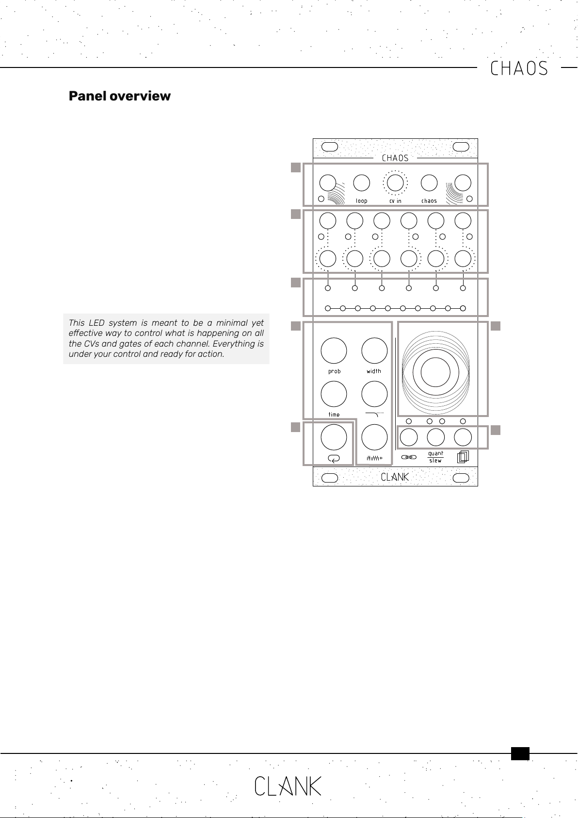
Panel overview
On Chaos’ rst row, from left to right, there are
four inputs (clock in, loop, cv in and chaos) and
one output (clock out) [1] . In the middle row there
are six gate outputs, one for each channel. A
dedicated LED blinks every time a gate signal is
sent. Under those you have the six corresponding
CV outputs (0v-8v) [2].
There are two LED bars on the module, one with
six LEDs and the other one with ten. The rst
one is the channel bar; it indicates the selected
channel in red and reects its real time CV
intensity by changing LED luminosity. The ten LED
bar is the value bar, and it is mainly thought for
editing purposes. Press any button to show the
parameter value. By default, if nothing is pressed it
will display the current channel’s CV output value.
[3]
This LED system is meant to be a minimal yet
eectivewaytocontrolwhatishappeningonall
the CVs and gates of each channel. Everything is
under your control and ready for action.
To change the selected channel, simply rotate the
encoder without pressing any other button. When
you reach the limit on the right all the LEDs will
become red, meaning you have selected all the
channels together. In this way you can easily loop
or change a modier or conguration at the same
time for all the channels [4].
The ve black buttons on the bottom left are the
modiers. (p.8-9) [5].
The white button is used to enter the loop mode.
(p.10) [6].
Hold down a modier to see the corresponding
value, rotate the encoder to change the value and
release the button when you are done.
The three small buttons placed under the encoder
correspond to the channel conguration [7]:
• Input assign/time swing
• Scale quantization/slewing
• Save/recall ability
1
2
3
4
7
5
6
5
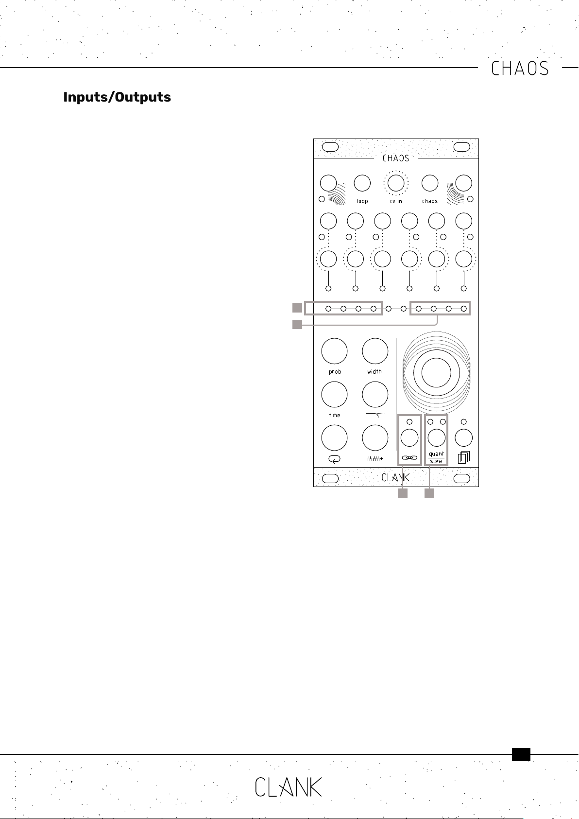
• Clock in is ideally activated by inputting a 50%
pulse width gate. A trigger or a triangular LFO
may be also inserted. When clock in is in use,
Channel 1 is automatically synced to it. Please
note that if clock in is patched but no signal
is being sent to it the module will perform no
actions.
• Loop in accepts a gate or a trigger signal
• CV in accepts a CV signal. All CV input assigns
operate between 0v and 8v except save/
recall 0v-5v; 0.5v for each save slot of the
selected bank (refer to save/recall section at
p.7)
• Chaos accepts a gate or a trigger signal
• Clock out outputs whichever master clock is
in use, the Channel 1 default master or the
clock in
Channel Settings
Channel Settings [1] can be used to access two
dierent but fundamental channel options: swing
and input assign.
Swing controls the time fraction expressed in
quarters with which a channel is delayed from
the master clock when the channel is synced to
it; input assign controls how channels are linked
to modiers through self-patching or external
devices communicating with Chaos’ inputs.
Keep in mind that every channel has its own
conguration.
To change a channel’s settings, hold the channel
settings button with the desired channel selected.
On the value bar, two sets of illuminated LEDs
will appear. The LEDs on the left (from 1 to 4) [2]
represent the swing value and the four LEDs on
the right (from 7 to 10) [3] reect the four inputs
at the top of the module (clock in, loop in, cv in
and chaos in) and their status. Rotate the encoder
CW or CCW to select an LED and press it to ip the
status.
When ON, LEDs on the left are Orange while LEDs
on the right are Green (LED 9 will also turn Red or
Orange as it controls dierent tasks).
When OFF, LEDs are white.
Inputs/Outputs
Swing
Swing is represented by four values (0, 1/4, 2/4
and 3/4) and only one value per channel at a time
can be ON. Keep in mind that swing is best used
when the channel in question is synced to the
master clock. (See TCM section p.8)
• LED 1 (default ON), swing value 0: When ON,
there is no delay from the master clock
• LED 2, swing 1/4: When ON, there is a 1/4
delay from the master clock
• LED 3, swing value 2/4: When ON, there is a
2/4 delay from the master clock
• LED 4, swing value 3/4: When ON, there is a
3/4 delay from the master clock
3
2
1 4
6
Input assign
The input assign section shows four statuses,
each one corresponding to the four inputs on the
top line of Chaos. Each status has two values, ON
or OFF, with the exception of LED 9 which controls
multiple tasks.
• LED 7 ON (default for channels 2 to 6): the
channel is synced to the master clock
• LED 7 OFF (default for channel 1): the channel
is un-synced and has its own timing expressed
in millisecond between consecutive beats
(see TCM section p.8)
• LED 8 ON (default): a gate sent in the loop in
will turn the loop function for this channel on
and o
• LED 8 OFF: sending a gate to loop in will not
aect the selected channel
• LED 9 GREEN ON: All the channel’s CV values
will be sampled from the CV in excluding the
internal random generator. Keep in mind that
modiers will still have eect on the sampled
voltage!
• LED 9 RED ON: The channel’s ground
transpose (see VCM section p.9) is controlled
by the values sampled from the CV in.
• LED 9 ORANGE ON: Hold the encoder until
the LED turns to orange. Now you can use
an external voltage patched into CV in to
move between the saved slots (0-5V). Hold
the encoder again to go back to normal
functionality.
VERY IMPORTANT: this last function is global and
not channel specic because the save/recall
function recalls every channel’s saved settings
from a save slot. (See save/recall section)
• LED 9 OFF (default): the internal random
voltage generator will be used to generate the
new values
• LED 10 ON (default): chaos mode can be
activated by a gate on the chaos input. The
input assign LED will quickly blink violet
• LED 10 OFF LED: gate signals on chaos
input won’t have any eects on the selected
channel
Scale quantization/slewing
To slew the selected channel, press the
quant/slew button once [4]. The right quant/slew
LED will light up in white to indicate that.
To choose a quantization mode, hold the quant/
slew button and turn the encoder at the same
time to scroll between the possible quantization
modes. To select a scale simply release the button.
The left quant/slew LED will stay on indicating the
current scale’s color. While keeping quant/slew
pressed, the current scale will be shown blinking
on the value bar as well.
There are three sets of modes. Each time you
reach the end of a set turning the encoder CW will
make it skip to the next set and vice versa. The
rst set includes 10 basic scales, the second set
includes the 7 modes of the melodic major scale,
and the third set includes the 7 modes of the
melodic minor scale.
First set:
• Unquantized (Default)
• Chromatic
• Octave
• Major pentatonic
• Minor pentatonic
• Blues
• Arabic
• Pelog
• Hirajōshi
• Chinese
Second set:
• Ionian
• Dorian
• Phrygian
• Lydian
• Mixolydian
• Aeolian
• Locrian
Third set:
• Ascending melodic minor
• Dorian b2
• Lydian augmented
• Lydian dominant
• Mixolydian b6
• Locrian #2
• Super Locrian

7
Save/Recall
Six banks of ten slots each are available for saving.
Hold down the save/recall button [1] to access
the save/recall menu. The channel bar indicates
which one of the six banks is selected, while the
value bar indicates the slots [2].
Turn the encoder to select the slot you prefer, after
the tenth one you’ll skip to the next bank.
Press the encoder to save a slot, release the save/
recall button to load one of the available slots.
The white LEDs on the value bar will indicate the
already saved slots.
Press the probability button [3] to clear the
selected slot. Recalling an empty slot will not have
any eects on your session.
When saving, an exact picture ofwhat is happening
at the moment will be taken and every channel
will be saved in its current state: if a channel is
looped, the sequence with all its modiers will also
be recorded.
Saving and recalling non-looped channels is
really useful for modulation or the recreation of a
mood based on recorded parameters rather than
exact sequences.
1
2
3

8
At its core, Chaos is composed of six channels
of clock generators [2], if no signal is applied to
the clock input [1], Channel 1 will be the master by
default.
All the channels can be individually synced to the
master clock or be completely time independent
(refer to Input Assign section p.6).
Probability [3] is a sort of coin toss to declare
if a gate of the selected channel will re or not.
Changing the probability value will reduce or
increase its possibility to happen. The range of
value is from 0% to 100%. If you’re using channel
1 as the master clock, changing its probability will
aect its gate output but not the master clock
data stream. If turned to zero both the channel’s
CV and gate will not output any signal.
Width [5] is the length of a gate’s duty cycle
expressed in percentage. Range is from 0%
(channel’s gate closed) to 100% (fully open).
Time [4] is expressed in two dierent ways,
depending on if a channel is quantized or not.
If the selected channel is the master clock or
if it’s not synced to it, time will be expressed in
milliseconds between two consecutive gates.
You can easily change it by pressing time and
turning the encoder. Rotating it CCW will result in
a faster clock, whereas rotating CW will make the
clock slower. This is because you will be reducing
or augmenting the milliseconds between two
consecutive gates.
Time range goes from 10ms to 10 seconds. In the
rst window, in white, every LED corresponds
to 10ms. By reaching the upper limit you will
enter a second window in blue. Here every LED
corresponds to 1 second. Default value is 500ms
(120bpm) each time the module is turned on.
If the selected channel is synced to the master
clock the Time button will work dierently letting
you set a multiplication or division of the master
itself. The pulse of the two-central LEDs on the
main bar means that the channel is at the same
rate of the master clock. Rotating the encoder
CW multiplies it (LEDs in white), CCW divides it
(LEDs in orange). The available multiplications and
divisions are from 1 to 8, then from 16 to 32.
Keep in mind that Chaos can emit gates from one
every 5.5 minutes to audio band (approximately
100hz) so timing changes can be very drastic.
Time Control Modiers
TIMING SHIFT / POLYRHYTHM
A simple way to create polyrhythms or explore
unconventional timings is to un-sync one or
more channels from the master clock and slowly
alter its/their timing. Depending on how far you
move the clock(s), you will go from out of phase
syncopation (Steve Reich Clap Music, anyone?) to
complete polyrhythmic madness.
2
1
3
4
5
9
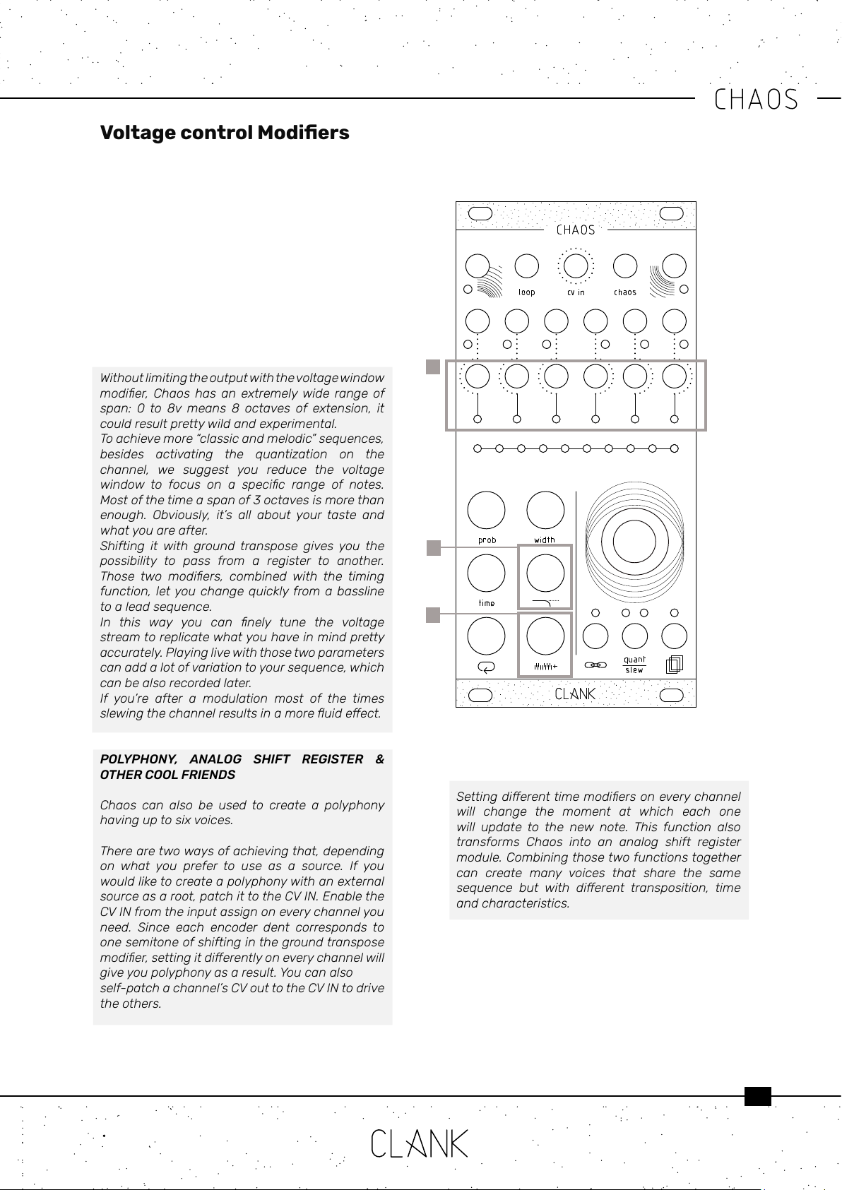
Every time a gate rises up a new random voltage
from 0 to 8v will be available on the CV output of
that channel [1].
With the voltage window [2] modier, you can limit
the number of values that the generator can pick
by reducing its maximum.
With the ground transpose [3] you can shift the
window of values that the generator can pick.
Every encoder dent will increase the ground by a
semitone.
Without limiting the outputwith thevoltage window
modier, Chaos has an extremelywide range of
span: 0 to 8v means 8 octaves of extension, it
could result pretty wild and experimental.
To achieve more “classic and melodic” sequences,
besides activating the quantization on the
channel, we suggest you reduce the voltage
window to focus on a specic range of notes.
Most of the time a span of 3 octaves is more than
enough. Obviously, it’s all about your taste and
what you are after.
Shifting it with ground transpose gives you the
possibility to pass from a register to another.
Those two modiers, combined with the timing
function, let you change quickly from a bassline
to a lead sequence.
In this way you can nely tune the voltage
stream to replicate what you have in mind pretty
accurately. Playing live with those two parameters
can add a lot of variation to your sequence, which
can be also recorded later.
If you’re after a modulation most of the times
slewingthechannelresultsinamoreuideect.
POLYPHONY, ANALOG SHIFT REGISTER &
OTHER COOL FRIENDS
Chaos can also be used to create a polyphony
having up to six voices.
There are two ways of achieving that, depending
on what you prefer to use as a source. If you
would like to create a polyphony with an external
source as a root, patch it to the CV IN. Enable the
CV IN from the input assign on every channel you
need. Since each encoder dent corresponds to
one semitone of shifting in the ground transpose
modier,settingitdierentlyoneverychannelwill
give you polyphony as a result. You can also
self-patch a channel’s CV out to the CV IN to drive
the others.
Voltage control Modiers
Settingdierenttimemodiersoneverychannel
will change the moment at which each one
will update to the new note. This function also
transforms Chaos into an analog shift register
module. Combining those two functions together
can create many voices that share the same
sequence but with dierent transposition, time
and characteristics.
1
2
3
10
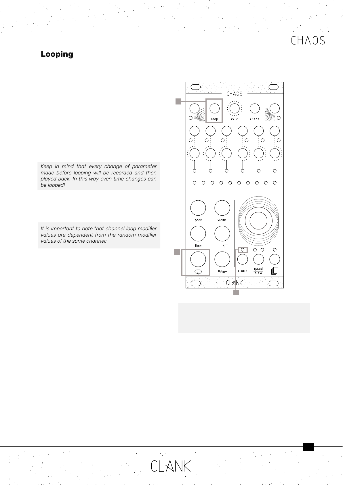
All six channels have an independent looping
capability. At all times, Chaos is keeping the last
32 steps memorized.
To start a loop, press the white loop button once
[1]. The value bar and the input assign [2] LED
will turn blue. Chaos is now in a loop that reects
everything that happened in the last steps.
The loop length can be changed by holding down
the loop button and by rotating the encoder to
select from 1 to 8 steps (LEDs 1 to 8 in YELLOW),
16 steps (LED 9 in ORANGE) or 32 steps (LED 10 in
RED) on the value bar. Press the loop button again
to exit from this mode.
Keep in mind that every change of parameter
made before looping will be recorded and then
played back. In this way even time changes can
be looped!
Whether Chaos is in loop mode or not, the
recorded sequence can be altered by holding the
loop button together with one of the ve modier
buttons.
Itisimportanttonotethatchannelloopmodier
values are dependent from the random modier
values of the same channel:
• The loop’s probability modier works within
the probability percentage of the channel’s
original probability value. That is to say that
if the channel’s original probability is at 70%,
that will be the loop’s probability maximum
value
• The loop’s width modier value can only be
increased from its original non-looped value
• The loop’s time modier works as a multiplier/
divider of the channel’s original random time
value
• The loop’s voltage window modier value
works similarly to probability, and therefore
can only be decreased from its original non-
looped value
• The loop’s ground transpose value works
similarly to width, and therefore can only be
increased from its original non-looped value
To reset loop values to their original state double
click the loop button, this way you can easily
transpose a loop or modify its timing and return to
the initial loop settings in a moment.
Looping
1
2
Please note that changing the original parameters of
the channel while the channel is in loop mode will not
alter the loop’s starting values, as loop memorizes a
state and operates on those values until it’s disabled.
Loop mode can also be activated by sending a gate
to its dedicated input [3]. In this case, the second
LED on the input assign menu has to be green.
With this workow, looping can be even more
expressive than just recording. It could be thought of
as a pre-determined variance to the whole random
generation!
3

11
Every time you press the encoder or send a gate
into the Chaos In [1], Chaos will re up and the
input assign LED will blink in purple.
Each time every modier value will be randomized
creating a new mood.
Since Chaos’ limits are very vast, changes can be
quite drastic.
That’s why entropy factor is pretty useful: it
represents the percentage of how much the
new value can variate from the one you have set.
Create subtle dierences or completely distant
moods.
Entropy can be set independently on each channel
or on one or more of each channel’s modiers. To
change the channel’s entropy, hold down and
rotate the encoder [2] CCW to reduce entropy, turn
it CW to increase it. The entropy percentage can
be visualized on the value bar.
To change a channel modier’s entropy, hold a
modier and the encoder at the same time, then
rotate the encoder CCW to reduce entropy, turn it
CW to increase it. The entropy percentage can be
visualized on the value bar.
When a channel modier’s entropy value is
changed it overrides the channel entropy value
when chaos is activated. When a channel’s general
entropy is changed it assigns that value to every
modier equally.
Chaos function can be used in many dierent
ways, self-patching a gate out to the Chaos
dedicated input [1] will bring you instantly into the
magic world of self-generating music. Limiting
the variance with low entropy on some channels
and setting the modiers to a preferred position
will create a “pseudo-controlled” but still random
environment where you set its starting point and
its limits, letting Chaos do the rest.
When you need help starting a new part, Chaos
functioncanquicklysuggestinnitecombinations
tochoosefrom.It’slikezappingbetweendierent
stylesormoods.Instead,ifyou’reprettysatised
of what you’ve created but you need to add some
variances to it, a low entropy use of the Chaos
function could be the way to go.
Combine it with loop and you will enjoy many
hours of evolving patterns and fun.
Chaos function
1
2
12
Calibration
ATTENTION: While on calibration mode, pressing the probability button anytime will erase all the saved memory
slots. If you do not wish for this to happen, please be very careful not to touch the probability button during the
entire calibration process.
Chaos CV outs are already calibrated by factory. If in some way the internal DACs scaling needs to be adjusted,
that can be done by following this procedure:
• Hold down the encoder while powering up the module.
• After the initial LED transition they all will turn purple.
• Now you can release the encoder and the rst channel LED will be selected.
• Connect the channel CV output to a multimeter.
• Turn the encoder untill you read a steady 8V voltage.
• When the rst channel is calibrated, press the encoder and it will skip to the next channel. Repeat that for
every channel and when the last one is set Chaos will go back to standard operation mode.
Firmware v1.03 Update
Firmware v1.01 new features:
• CV in controlled ground transpose
• Chaos entropy regulable for each modier
• New scales/quantizations
• Time swing
• All known bugs xed
To update your Chaos just follow these easy steps:
• First, go to https://www.silabs.com/developers/usb-to-uart-bridge-vcp-drivers and click on the Downloads
tab. Download and install the “CP210x Driver” compatible with your device.
• Next, go to https://www.st.com/en/development-tools/stm32cubeprog.html#get-software and download
and install the “STM32CubeProgrammer” le compatible with your device. [Please note that to download the
software you will have to have an st.com account or leave your name and email address. There are no fees
to register and download.]
• Finally, go to https://www.clank.eu/chaos and download the rmware .bin le from the link at the bottom of
the page.
IMPORTANT: At this point, please make absolutely sure that your Chaos module is NOT attached to any kind of
power source.
• Connect the micro-USB end of a micro-USB/USB cable to Chaos. While holding down the BOOT button [next
to the micro-USB port on the backside of the module], insert the USB end of the cable into your computer.
Once this is done you may release the BOOT button.
• Next, open the Cube programmer. Select UART, and the correct port. On MAC devices it should appear as “cu.
SLAB_USBtoUART”. On Windows it is usually the COM port with the highest number. If the port should not be
listed, try refreshing the port list. If this doesn’t work as well, try repeating the boot process.
• Once you have selected the correct port, click on “Connect”. Your device should be recognized immediately.
• Next click on “Open le”. Find the rmware’s .bin le and open it. Click on “Download” and the rmware should
be installed within seconds. Click on “Disconnect” and you’re all done.
• If you have correctly installed rmware v1.01, when the Chaos module is powered up, the initial LED ash
should be red, whereas rmware v1 will ash white.
Other manuals for Chaos
2
Table of contents
Popular Recording Equipment manuals by other brands


Trilithic
Trilithic Visionary HD/SD Overlay System Hardware installation and configuration manual

AudioArts
AudioArts RD Technical manual

SoundArt
SoundArt Chromasonic user manual

Car Solutions
Car Solutions ML2012-TDC user manual

Frequency Central
Frequency Central Cryptograph Build documentation

Mercury Security
Mercury Security MR62e Installations and specifications