manuals.online logo
Brands
  1. Home
  2. •
  3. Brands
  4. •
  5. Clarion
  6. •
  7. Car Receiver
  8. •
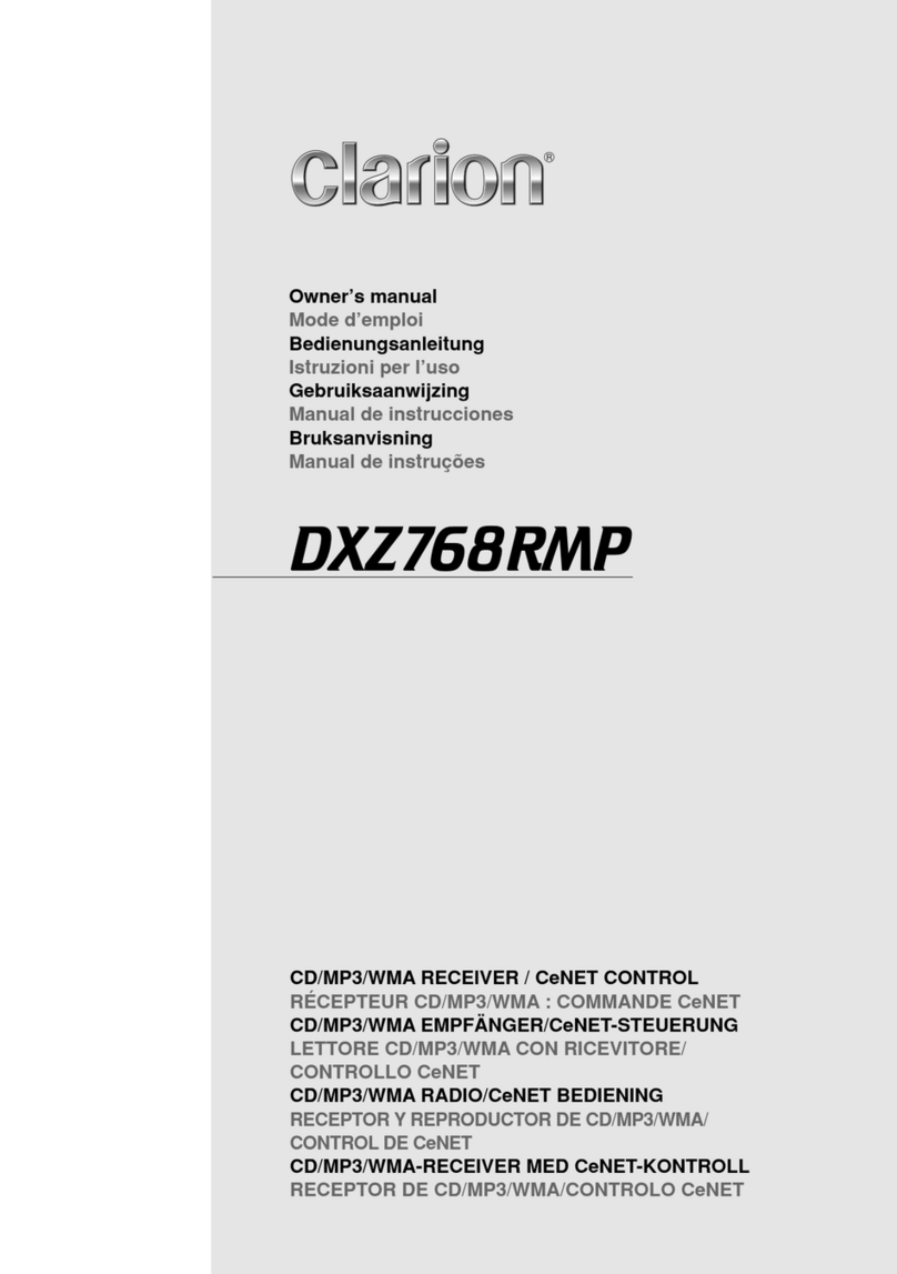
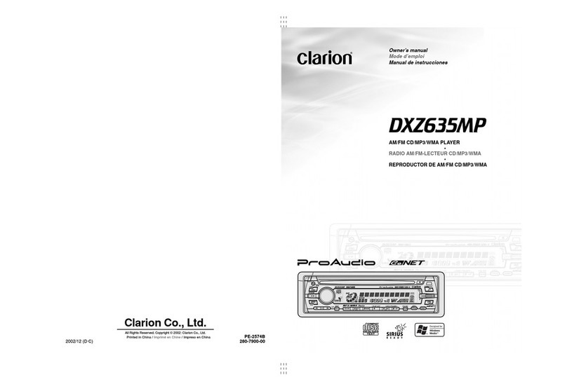
  9. Clarion DXZ946MP Instruction Manual

Clarion DXZ946MP Instruction Manual

1
2
3
4
1Stopper/ᇌ׵ఝӐ/스토퍼
2Source Unit/ᇽࠖ/본체
3Screwdriver/ઋර֞/드라이버
4Screw/ઋර/나사
Figure 6 / ๴6 / 그림 6 Figure 7 / ๴7 / 그림 7Figure 5 / ๴5/ 그림 5
Installation/Wire Connection Guide


/ ! !
 ! !
 !


/

==
==
=


1. This set is exclusively for use in cars with a
negative ground, 12 V power supply.
2. Read these instructions carefully.
3. Be sure to disconnect the battery “v” terminal
before starting. This is to prevent short circuits
during installation. (Figure 1)
1.  !"#$%&'12V !"#$%

2.  !"#$%&'
3.  !"#$%&'()v !"#
 !"#$%&'(1F
Figure 1 / 

1 / 

 1
Car battery
డӡ׏Ԅ
차 배터리
2003/12 (AB·C) 284-9905-00 ■PRECAUTION
Remove the stopper following the procedures below when this source unit is installed
without the universal mounting bracket.
1. Remove the screw from the source unit (Figure 5).
2. Remove the stopper from the source unit (Figure 6).
3. Install the remove screw to the source unit (Figure 7).
∗Securely attach the screw.
■ ! !
 ! !
 !
= = !== = = = = == !=
 !K
1.  != = !"K=E=5F
2.  != != !"K=E=6F
3.  = = = !"K=E=7F
∗ == !"#K
■ ! !
 ! !
 !
 !"!#$%&'()*+#,-./*012345678
1.  !"#$%&'5
2.  !"#$%&'(6
3.  !"#$%&'()*+7
∗ !"#$%
■Universal Mount
1. Place the universal mounting bracket into the instrument panel, use a
screwdriver to bend each stopper of the universal mounting bracket
inward, then secure the stopper as shown in Figure 4.
2. Wire as shown in Section 6.
3. Insert the source unit into the universal mounting bracket until it
locks.
4. Take care of the top and bottom of the outer escutcheon and mount it
so that all the hooks are locked.
■ !"#
1.  !"#$%&'()*+ ,-. !"#$/0123
 !"#$%&'4 !"#$%
2. 6 !"#$
3.  !"#$%&!'()*+,-./
4.  !"#$%&'(&)*+,-.$/012345
■=
1. = = != ==I= !"==
 != !== != !==4==
= != !"#K
2. =6= === = K
3.  == !== = !K
4. = !== = != == != !
K
(182 mm)
Outer escutcheon
ບ૲আ
외부 프레임
Instrument panel
ၕѝϷ
계기반
Hole

홀
Hexagonal bolt
࢟ઋඤ
육각형 볼트
Stoppers
ᇌ׵ఝ
스토퍼
Stoppers
ᇌ׵ఝ
스토퍼
Screwdriver
ઋර֞
드라이버
Universal mounting bracket
๠Ⴏሔ஬ᆭࡖ
일반 탑재용 받침대
Strap
༵๏
스트랩
* This part is not provided in some models.
* ՕࡸᄤႼཻࠖྟેႼ฻܉è
* 이 부품은 일부 모델에는 제공되지 않습니다.
Source Unit
ႂჾሔᇉ
본체
• Console opening dimensions
• ᇌขԋձ
• 콘솔 입구 크기
7-3/16"
2-1/8"
Hole

홀
53 mm
Note:
Before attaching the universal mounting bracket, slightly bend
the spring toward the inside with your fingers and attach it to the
side of car.
ሆĈ
τሔ๠Ⴏሔ஬ᆭࡖᆴఴƗ౯Ⴏ൴ᆾࢃ֗ߥഔསୄҮຜƗࢃఊτሔ
ᄤడӡ၉Үè
주:
일반 탑재용 받침대를 부착시키기 전에, 스프링을 손가락으로
약간 안쪽으로 구부린 다음 차 쪽으로 부착시키십시오.
Spring
֗ߥ
스프링
Top
׫ҍ
위
Bottom
ֿҍ
아래
Installation direction
τሔ١ས
설치 방향
Outer escutcheon side view
ບ૲আҮ൱๴
외부 프레임을 옆에서 본 그림
1. Prepare all articles necessary for installing the source unit before
starting.
2. Install the unit within 30° of the horizontal plane. (Figure 2)
3. If you have to do any work on the car body, such as drilling holes,
consult your car dealer beforehand.
4. Use the enclosed screws for installation. Using other screws can
cause damage. (Figure 3)
1.  !"#$%&'()*(+,-./0123
2.  !"#$%&'()*+,-30° E2F
3.  !"#$%&'()*+,-.,/01#234567
4.  !"#$%&'()* +,$%-./012*E3F
Note:
Store the removed stopper in a safe place together with the Instruction Manual.

 !"#$%&'()*+,-./0!1234567


WW
WW
W
 = != !"#== = = !"#K
■Fixed Mount (Using the bracket originally equipped in vehicle)
This unit is designed for fixed installation in the dashboard.
If the vehicle is equipped with a factory-installed radio, install the source unit with the
parts and screws marked (★). (Figure 11)
If the vehicle is not equipped with a factory-installed radio, obtain an installation kit to
install the source unit in the following procedure.
1. Secure the mounting brackets to the chassis as shown in Figure 11. When the
source unit is installed without the universal mounting bracket, holes exist;
modification, such as drilling new holes, of the mounting brackets may be required
for other models.
2. Wire as shown in Installation (Section 6).
3. Secure the unit in the dashboard, and then reassemble the dashboard and the
center panel.
■ ! !
 ! !
 !
EE
EE
E !"#$%&' !"#$%&'
 !"#$%&' !"#$%&'
 !"#$%&'ISO/DN


FF
FF
F
 !"#$%&'()*+
 !"#$%&'(")*+,-./0123EGF !"#$%&'%()
11
 !"#$%&'(#)*+,-./0(#12345678(#,9#:;
1. NN !"#$%&'()*+,(-./0/"#$%12345"67
 !"#$%&'()*+,-./012%3456789':(
2. 6 !"#$
3.  !"#$%&'()*+,-. %&'/01'2
■

==
==
=

=E=E
=E=E
=E ! !
 ! !
 !==
==
= ! !
 ! !
 !==
==
=

 ==
==
= ! !
 ! !
 !==
==
=

FF
FF
F
== !== = = = !"K=== =
= = !I===EF== = = = !"#K
E11F
= = != !== !I== = = ==
= = !"#K
1. =NN===== != = !"#K==
 !== = =I= === X===
=I== ==== != = == !K
2. E=6F= === = K
3.  != = !=I= !== == !"#K
Notes:
1) Some car models require special mounting kits for proper
installation. Consult your Clarion dealer for details.
2) Fasten the front stopper securely to prevent the source unit from
coming loose.



1)  !"#$%&'()*+,-.&/012345Clarion
 !"
2)  !"#$%&'()*"+


WW
WW
W
1) = =I= = = = == =
== !K= ==`ä~êáçå= = !"#K
2)  = !== != = !"==
 !K
Center Panel (Note 1)
ᇖရϷሆ 1
센터 패널 (주 1)
Figure 11 / ๴11 / 그림 11
Source Unit
ႂჾሔᇉ
본체
Mounting bracket
*
(1 pair for the left and right sides)
ሔ஬ᆭࡖ
*
၉ؚႯ჆቗ႾҮ
탑재 받침대
*
(왼쪽과 오른쪽의 한짝)
Dashboard
ၕѝϷ
계기반
Pocket
ގ
포켓
★
★
★
★
★
4–Hexagonal screw
*
(M5
×
8)
4۸࢟ઋර
*
(M5
×
8)
4개의 육각형 나사
*
(M5
×
8)
Note 2 / ሆ2 / 주2
★
∗:The parts and SCREW with this mark are used to install radio or included in the
installation kit.
★:The screws with this mark are originally attached to the vehicle.
Note 1: In some cases, the center panel may require some modification (trimming, filling,
etc.).
Note 2: If a hook on the installation bracket interferes with the unit, bend and flatten it
with a nipper or a similar tool.
∗: !"#$%&'()*+,-./012*+3456
★: !"#$%&'()"*


1

 !"#$%&'()* !E !"#F


2

 !"#$%&'()*!+ !"#$%&'()*+,-.
∗:= = = = = = = !I== = !
 !K
★:= = = = != != !== !K


==
==
=1: = == == = = !K=EI==F


==
==
=2:= === = =I= == = !=
 = !K
1. = =12VI=åÉÖ~íáîÉ=ÖêçìåÇ=
 == = !"K
2. = !"#=== !"#K
3.  != = !=“v”= =
 !K= = = = !=
= K=E=1F
Max. 8 mm / ቒս 8mm / 최대 8 mm
Chassis / ֿஔ / 차대 Chassis / ֿஔ / 차대
Damage / ෬ߑ / 손상
Max. 30˚ / ቒս 30˚ / 최대 30˚
1.  !== = = == !"#K
2.  = !=30°= = !"#K=E=2F
3.  = ==== = =I= ==
= !"#K
4.  = = != !"#K== = !=
= === !K=E=3F
Figure 2 / 

2/ 

 2 Figure 3 / 

3/ 

 3
Figure 9 / ๴9 / 그림 9 Figure 10 / ๴10 / 그림 10Figure 8 / ๴8 / 그림 8
1
2
■PRECAUTION
Push in the protruding part as shown in the figure.
■ሆၰൠར
೉๴෵൜๾್๳Ԣҍٺè
■주의사항
돌출된 부분을 그림에서 보는 바와 같이 밀어 넣습니다.
1Stopper/ᇌ׵ఝ/스토퍼
2Source Unit/ႂჾሔᇉ/본체
1. When removing the source unit, disassemble it in the reverse of the order in
Section “3. INSTALLING THE SOURCE UNIT”.
2. Remove the Detachable Control Panel (DCP).
∗For instructions on removing the DCP, refer to the owner’s manual.
3. Press the outer escutcheon upward and remove it. (Figure 12)
4. Insert and lock the hook plates. (Figure 13)
5. Pull the hook plates to remove the source unit.
1.  !"#$%&'()33.  !"#$%&'()*+,
2.  !"#$%EDCPF
∗ !"#$%EDCPF !"#$%&'()*
3.  !"#$%&'()* 12
4.  !"#$%&= 13
5.  !"#$%&'()*
Figure 12 / ๴12 / 그림 12
2–Hook plate
2۸ܲܓϷ
2개의 훅 플레이트
Outer escutcheon
ບᅾ
외부 프레임
Figure 13 / ๴13 / 그림 13
Figure 4 / 

4/ 

==
==
=4
BEFORE STARTING /  ! !
 ! !
 ! / 


1.





English
INSTALLING THE SOURCE UNIT
/
 !"
/


==
==
=


3.
CAUTIONS ON INSTALLATION
/
 !"#$% !"#$%
 !"#$% !"#$%
 !"#$%
/ 

 ==
==
= ! !
 ! !
 !
2.





English






English
1.  = =I==“3. =”== != !"#K
2.  = =EDCPF= !"K
∗DCP= == == != !"#K
3. = != != = !"K=E 12F
4. = !"== !K=E 13F
5. = !"= = = !"K


 

English


 

English
Example 1/

1/

1 Example 2/

2/

2
CAUTIONS ON WIRING
/
 !"#$% !"#$%
 !"#$% !"#$%
 !"#$%
/
 ! !
 ! !
 !==
==
= ! !
 ! !
 !
5.
REMOVAL OF THE SOURCE UNIT
/
 !"# !"#
 !"# !"#
 !"#
/


==
==
=


4.
■1. Be sure to turn the power off when wiring.
2. Be particularly careful where you route the wires. Keep them well away from
the engine, exhaust pipe, etc. Heat may damage the wires.
3. If the fuse should blow, check that the wiring is correct.
If it is, replace the fuse with a new one with the same amperage rating as the
original one. (Figure 14)
Note:
There are various types of fuse holder. Do not let the battery side touch other
metal parts.
4. Connect the CeNET extension cable fully and securely until it locks. When the
CeNET extension cable is pulled, hold the slide cap part and pull it towards you.
∗When the CeNET extension cable is extended or branches, use extension
cable CCA-520 (2.5m) or CCA-521 (0.6m), or Y-adapter CCA-519 (each of
them is sold separately).
∗Use the CeNET extension cable made by Clarion.
5. When the main power supply fuse in the car is 15 A or less, purchase an
automotive cable that can withstand 15 A and supply this unit with power
directly from the battery to ensure that the unit will operate normally.
Note that a fuse must be installed at a distance no longer than 30 cm from the
cable battery terminal to prevent accidents.
■1.  !"#$%&'
2.  !"#$%&'  !"#$%&'()*+= !"#$%&
3.  !"#$%&'()*+,-./
 !"#$%&'()*+,-./0123456+,-789E14F



 !"#$%&'()*+,-./012%3456789:;<=*
4.  !"CeNET !"#$%&'()CeNET !"#$%&'(
 !"#$%&'(
∗CeNET !"#$%&'()*+ !CCA-5202.5 CCA-
5210.6 !v !CCA-519 !"#$
∗Clarion CeNET !"
5.  !"#$%&'()#*+,-./15 !"#$%&'()*+,
15 !"#$%&'()*+*,!"#-./0123&'(4567
 !"#$%&'()*+#,-./01230 !"#$I !
 !
■1.  === = == !K
2.  !== == = !"K !=I= =
 != = ==I=== == ==
K
3.  = =I= = == = !"#K
 = = I= = == = !== =
= !KE=NQF


WW
WW
W
 = == = !K= !== ===
== = !K
4. CeNET== != = == != !"= K
CeNET== = = I= !== == !=
 !K
∗CeNET== !=== === !=CCA-520
E2.5mF==CCA-521=E0.6mF==YJ =CCA-519= = !
E=FK
∗Clarion=CeNET== != !"#K
5.  !==== =15^= =I=== =
15A==== !"==== = ===
= != != !K
= == = = = = !"=30 cm= =
= !"= == !"#K
Fuse case
保险丝盒
퓨즈 케이스
Fuse
保险丝
퓨즈
Figure 14 / 

14 / 

==
==
=14
■ DXZ946MP/DXZ746MP
■ DXZ646MP
■ DXZ846MC
■ DXZ546MP
9
0
1
2
3
4
7
8
CeNET input
CeNET 输入
CeNET 입력
Antenna
天线
안테나
7
8
9
0
CeNET input
CeNET 输入
CeNET 입력
Antenna
天线
안테나
7
8
Antenna
天线
안테나
CeNET input
CeNET 输入
CeNET 입력
1
2
3
4
9
0
Antenna
天线
안테나
CeNET input
CeNET 输入
CeNET 입력
1
2
3
4
!
@
!
@
!
@
1
2
5
6
9
0
!
@
To external amplifier
*To eliminate audio short circuits, do not remove the caps of unused RCA cables.
CAUTION: Please make sure when connecting external power amplifier, that you properly, to the car
chassis, ground the amplifier. If this is not done, severe damage to the source unit may
happen.
至外部放大器
*为避免音频短路,不要卸下不使用的RCA电缆帽。
注意:连接外部电源放大器时,请务必注意正确地进行放大器至汽车底盘的接地,否则,可能会严重损坏主机。
외부 앰프로
*오디오 쇼트가 일어나지 않도록, 미사용 RCA 케이블에 씌운 캡을 분리하지 마십시오.
주의 : 외부의 파워 앰프와 연결시, 앰프가 차대에 올바르게 어스되어 있는 지 확인해 주십시오. 그렇지
않으면 본체가 심한 손상을 입을 수도 있습니다.
To external unit
至外部设备
외부 기기로
To wireless head phone UNIT
至无线耳机组件
무선 헤드폰 유닛으로
Brown wire (Phone mute lead)★
褐色引线(电话静音接线)★
갈색 케이블 (전화 뮤트 리드)★
Connect to cellular phone mute lead.
连接至手机静音接线。
휴대폰 뮤트 리드로 연결한다.
Connect to remote turn-on lead of amplifier.
连接至放大器的遥控启动线。
앰프의 원격 기동 리드로 연결한다.
Connect to vehicle chassis ground.
连接至汽车底盘地线。
자동차의 차대 어스로 연결한다.
Connect it to the car power supply terminal for the antenna.
将其连接至用于天线的汽车供电端子。
자동차의 안테나용 전원 공급 단자로 연결한다.
Yellow wire (Memory back-up lead)
黄色引线(备用存储器线)
노란색 케이블 (메모리 백업 리드)
Yellow wire (Bus power lead)★
黄色引线(母线电源线)★
노란색 케이블 (버스 전원 리드)★
Red wire (Power lead)
红色引线(电源线)
빨간색 케이블 (전원 리드)
Blue/White wire (Amplifier turn-on lead)
蓝色/白色引线(放大器接通线)
파란색/흰색 케이블 (앰프 기동 리드)
Black wire (Ground lead)
黑色引线(地线)
검은색 케이블 (어스 리드)
Blue wire (Auto antenna lead)
蓝色引线(自动天线接线)
파란색 케이블 (자동차 안테나 리드)
Orange/White wire (Illumination lead)
橙色/白色引线(照明线)
오렌지색/흰색 케이블 (조명 리드)
Connect directly to battery.
直接连接至电池。
배터리로 직접 연결한다.
AccessoryB12 V
附件B12 V
액세서리 B12 V
Fuse (15A)
保险丝(15A)
퓨즈 (15A)
Connect directly to battery.
直接连接至电池。
배터리로 직접 연결한다.
Fuse (3A)
保险丝(3A)
퓨즈 (3A)
Front Right
前置右侧
앞면 오른쪽
Front Left
前置左侧
앞면 왼쪽
Rear Right
后置右侧
뒷면 오른쪽
Rear Left
后置左侧
뒷면 왼쪽
Right
右侧
오른쪽
Left
左侧
왼쪽
BGray / B灰色 / B회색
BWhite / B白色 / B흰색
BPurple / B紫色 / B보라색
BGreen / B绿色 / B녹색
vGray/Black / v灰色/黑色 / v회색/검은색
vWhite/Black / v白色/黑色 / v흰색/검은색
vPurple/Black / v紫色/黑色 / v보라색/검은색
vGreen/Black / v绿色/黑色 / v녹색/검은색
BGray / B灰色 / B회색
vGray/Black / v灰色/黑色 / v회색/검은색
BWhite / B白色 / B흰색
vWhite/Black / v白色/黑色 / v흰색/검은색
BPurple / B紫色 / B보라색
v
Purple/Black
/ v紫色/黑色 / v보라색/검은색
BGreen / B绿色 / B녹색
vGreen/Black / v绿色/黑色 / v녹색/검은색
4-Speaker system
4扬声器系统
4-스피커 시스템
or
或
또는
2-Speaker system
2扬声器系统
2-스피커 시스템
Not used.
Insulate each wire.
不使用。
将各导线绝缘。
사용안함.
각 전선을 절연.
16-Pin Connector Extension Lead
(attached to the source unit)
16芯连接器扩展导线
(连接至音源装置)
16-핀 연결 연장 리드
(본체에 부착되어 있음)
Connect it to the car power supply terminal for illumination.
将其连接至汽车电源接线端,用以照明。
자동차의 조명용 전원 공급 단자로 연결한다.
∗This source unit can control a total of 2 changers except 2 DVD changers exist in the system.
∗ !"#2DVD !" #$%&2 !"
∗= = != !=2=DVD= ==2= != == !K
WIRE CONNECTIONS / 

 / 


6. SYSTEM EXAMPLE / 

 / 

 ==
==
=


7.
GENERAL CAUTIONS /  !"# !"#
 !"# !"#
 !"# /  ! !
 ! !
 !==
==
= ! !
 ! !
 !
8.
1. Do not open the case. There are no user serviceable parts inside. If
you drop anything into the unit during installation, consult your dealer
or an authorized CLARION service center.
2. Use a soft, dry cloth to clean the case. Never use hard cloth, thinner,
benzen, alcohol, etc. For tough dirt, apply a little cold or warm water
to a soft cloth and wipe off the dirt gentry.
IMPORTANT:
Improper installation may cause damage to your unit or car. If you do
not have the appropriate experience, consult a qualified installer.
Cutting chassis wire leads voids the warranty.



 !"#$%&'()*+,-./0123456789:
 !"#$%&'()*+,-./01%


WW
WW
W
 != = !== != ===
K=== == == = ==
= !"#K= = = = == !"=
== !K
NK  !"#$%&'()*+,-./0&1$23456789
 !"#$%&'()*+,CLARION !"#$%&
OK  !"#$%&'()*+,#-./0-123456(7
 !"#$%&'()*+,-.,//012
NK  !== !K= !"= !=== =
 !K= != = !"=I= = !"=
 =CLARION== = = !"#K
OK  != !== !=== !"#K=
 =I=I==== != !K= !"
 !I== !"= ==== ==
= !K
Note:
Use a CeNET extension cable that is less than 20 m in length. (including the Y-adapter CCA-519.)


:
 !"20 mCeNET !"#$v CCA-519


:
 =20 m= =CeNET== != !"#K=Ev =CCA-519=F






English 





English
Clarion Co., Ltd.
English 





English
kçKkçK
kçKkçK
kçK 


1= ==E F
2===EF
3= = =E F
4== =EF
5= =L=E != F= =E F
6==L=E !=F= =EF
7 != = =E F
8 !== =EF
9AUX== = =E F
0AUX=== =EF
!2J== ==E F
@2J====EF
No. Description
1FRONT RIGHT Gray (Red)
2FRONT LEFT Gray (White)
3REAR RIGHT Black (Red)
4REAR LEFT Black (White)
5REAR RIGHT/(SUB WOOFER RIGHT) Black (Red)
6REAR LEFT/(SUB WOOFER LEFT) Black (White))
7SUB WOOFER RIGHT Violet (Red)
8SUB WOOFER LEFT Violet (White)
9AUX INPUT RIGHT Red (Red)
0AUX INPUT LEFT Red (White)
!2-ZONE OUTPUT RIGHTGreen (Red)
@2-ZONE OUTPUT LEFTGreen (White)
English


 


1 = !"
2 = !"
3 = !"
4 = !"
5 L !"#$= !"#$"
6 L !"#$= !"#$"
7 !"#=== !
8 !"#== !"
9 !== !
0 !== !"
! !== !"
@ !== !"
Note:
Some units do not have connecting leads or jacks.
(Refer to
★
.)



 !"#$%&'()*
 ★


WW
WW
W
= ======== !K
E★=F
Source unit
CeNET extension cable
Y-adapter (sold separately)
CD changer
DVD changer
RCA extension cable (sold separately)
4-Channel power amplifier
Front speakers
Rear speakers
Monitor
TV tuner module
5.1ch surround decoder
5.1ch surround decoder control unit
Optical connector cable
Center speaker (with amplifier)
Subwoofer (with amplifier)
External unit
Wireless head phone unit
1
2
3
4
5
6
7
8
9
0
!
@
#
$
%
¥
&
*
 !
CeNET !
Y !"#$%
CD
DVD
RCA !"#$%
4 !"#$
 !"
 !"

TV !"
5.1 !"#$
5.1 !"#$%&'(
 !"#$%
 !"#$%&"'
 !"#$%&'#(
 !
 !"#
1
2
3
4
5
6
7
8
9
0
!
@
#
$
%
¥
&
*

CeNET==
YJ =E=F
CD=
DVD=
RCA== =E=F
4J==
 =
=

TV==
5.1= !=
5.1= != = =
= =
= =EF
 !=EF
=
= =
1
2
3
4
5
6
7
8
9
0
!
@
#
$
%
¥
&
*
■Example of the system using an external amplifier (Audio Visual)
■ !"#$%&'()*+,-.,/ !"#$%&'()*+,-.,/
 !"#$%&'()*+,-.,/ !"#$%&'()*+,-.,/
 !"#$%&'()*+,-.,/
■

==
==
=

==
==
=

==
==
= ! !
 ! !
 !==
==
=

 =E=E
=E=E
=E

==
==
=

FF
FF
F
!
0
6
@
3
4
89
7
5
¥
Amp
Amp
2
6
$
%
&
1(
*
!
0
6
@
3
89
7
#
¥
Amp
Amp
2
$
%
6
&
(*
1
■DXZ946MP/DXZ746MP ■DXZ846MC/DXZ646MP/DXZ546MP
4
5













Other manuals for DXZ946MP

1

This manual suits for next models

4

Other Clarion Car Receiver manuals

Clarion DMX5555z User manual

Clarion

Clarion DMX5555z User manual

Clarion SIRIUS DSC920S User manual

Clarion

Clarion SIRIUS DSC920S User manual

Clarion DXZ958RMC User manual

Clarion

Clarion DXZ958RMC User manual

Clarion ProAudio DXZB35MP User manual

Clarion

Clarion ProAudio DXZB35MP User manual

Clarion CZ209 User manual

Clarion

Clarion CZ209 User manual

Clarion FZ.150 Repair manual

Clarion

Clarion FZ.150 Repair manual

Clarion CZ209 User manual

Clarion

Clarion CZ209 User manual

Clarion DXZ676USB User manual

Clarion

Clarion DXZ676USB User manual

Clarion CZ102 User manual

Clarion

Clarion CZ102 User manual

Clarion CZ500A User manual

Clarion

Clarion CZ500A User manual

Clarion CZ101 Repair manual

Clarion

Clarion CZ101 Repair manual

Clarion DXZ576USB User manual

Clarion

Clarion DXZ576USB User manual

Clarion NX500 Original instructions

Clarion

Clarion NX500 Original instructions

Clarion PS-2808K-A User manual

Clarion

Clarion PS-2808K-A User manual

Clarion AXZ610 User manual

Clarion

Clarion AXZ610 User manual

Clarion DXZ375MP Instruction Manual

Clarion

Clarion DXZ375MP Instruction Manual

Clarion HX-D2 Instruction Manual

Clarion

Clarion HX-D2 Instruction Manual

Clarion DXZ865MP User manual

Clarion

Clarion DXZ865MP User manual

Clarion DXZ755MC Instruction Manual

Clarion

Clarion DXZ755MC Instruction Manual

Clarion BD239R/BD239RG User manual

Clarion

Clarion BD239R/BD239RG User manual

Clarion DXZ758RMC User manual

Clarion

Clarion DXZ758RMC User manual

Clarion HX-D2 User manual

Clarion

Clarion HX-D2 User manual

Clarion DRX9575Rz User manual

Clarion

Clarion DRX9575Rz User manual

Clarion FZ501 Repair manual

Clarion

Clarion FZ501 Repair manual

Popular Car Receiver manuals by other brands

Sony CDX-M770 - Fm/am Compact Disc Player Installation/connections

Sony

Sony CDX-M770 - Fm/am Compact Disc Player Installation/connections

JVC KD-Lh401 Service manual

JVC

JVC KD-Lh401 Service manual

AMS CT410 owner's manual

AMS

AMS CT410 owner's manual

Kenwood KDC-508 instruction manual

Kenwood

Kenwood KDC-508 instruction manual

Blaupunkt MADRID 120BT owner's manual

Blaupunkt

Blaupunkt MADRID 120BT owner's manual

Magnadyne RV5055 Operation and installation manual

Magnadyne

Magnadyne RV5055 Operation and installation manual

JVC KD-AVX2 - DVD Player With LCD Monitor Installation & connection manual

JVC

JVC KD-AVX2 - DVD Player With LCD Monitor Installation & connection manual

Pioneer DEH-P5500MP Operation manual

Pioneer

Pioneer DEH-P5500MP Operation manual

Pioneer Super Tuner III D Operation manual

Pioneer

Pioneer Super Tuner III D Operation manual

LENCO CS-175 instruction manual

LENCO

LENCO CS-175 instruction manual

Pioneer DEH-P8100BT installation manual

Pioneer

Pioneer DEH-P8100BT installation manual

Blaupunkt ACD 2800 user guide

Blaupunkt

Blaupunkt ACD 2800 user guide

MAXTEK 5371 user guide

MAXTEK

MAXTEK 5371 user guide

JVC KD-APD49 - CD/AM/FM/MP3/WMA Receiver instructions

JVC

JVC KD-APD49 - CD/AM/FM/MP3/WMA Receiver instructions

JVC KD-SH1000E Installation & connection manual

JVC

JVC KD-SH1000E Installation & connection manual

Sony CDX-R5715X - Fm/am Compact Disc Player operating instructions

Sony

Sony CDX-R5715X - Fm/am Compact Disc Player operating instructions

Kenwood KRC-12 instruction manual

Kenwood

Kenwood KRC-12 instruction manual

Sony XR-C610 manual

Sony

Sony XR-C610 manual

manuals.online logo
manuals.online logoBrands
  • About & Mission
  • Contact us
  • Privacy Policy
  • Terms and Conditions

Copyright 2025 Manuals.Online. All Rights Reserved.