manuals.online logo
Brands
  1. Home
  2. •
  3. Brands
  4. •
  5. Clarion
  6. •
  7. Car Stereo System
  8. •
  9. Clarion CD037RMP User manual

Clarion CD037RMP User manual

Other Clarion Car Stereo System manuals

Clarion MAX385VD Quick start guide

Clarion

Clarion MAX385VD Quick start guide

Clarion CZ309 User manual

Clarion

Clarion CZ309 User manual

Clarion DXZ645MP Operating instructions

Clarion

Clarion DXZ645MP Operating instructions

Clarion Net DXZ638RMP User manual

Clarion

Clarion Net DXZ638RMP User manual

Clarion DB625MP User manual

Clarion

Clarion DB625MP User manual

Clarion DB158RB Assembly instructions

Clarion

Clarion DB158RB Assembly instructions

Clarion PH-2416I User manual

Clarion

Clarion PH-2416I User manual

Clarion iDXZ378RMP User manual

Clarion

Clarion iDXZ378RMP User manual

Clarion DRX9255 User manual

Clarion

Clarion DRX9255 User manual

Clarion VRX785BT Repair manual

Clarion

Clarion VRX785BT Repair manual

Clarion DXZ776usb Instruction Manual

Clarion

Clarion DXZ776usb Instruction Manual

Clarion PN-2083I User manual

Clarion

Clarion PN-2083I User manual

Clarion NX501 Repair manual

Clarion

Clarion NX501 Repair manual

Clarion CDC5030 User manual

Clarion

Clarion CDC5030 User manual

Clarion DXZ758RMC User manual

Clarion

Clarion DXZ758RMC User manual

Clarion PN-2548N User manual

Clarion

Clarion PN-2548N User manual

Clarion PN-3124N-A User manual

Clarion

Clarion PN-3124N-A User manual

Clarion DB258R Assembly instructions

Clarion

Clarion DB258R Assembly instructions

Clarion ProAudio ARX7570z User manual

Clarion

Clarion ProAudio ARX7570z User manual

Clarion DXZ465MP Assembly instructions

Clarion

Clarion DXZ465MP Assembly instructions

Clarion DRX9255 User manual

Clarion

Clarion DRX9255 User manual

Clarion DXZ476MP Instruction Manual

Clarion

Clarion DXZ476MP Instruction Manual

Clarion CX609E User manual

Clarion

Clarion CX609E User manual

Clarion VRX775VD Repair manual

Clarion

Clarion VRX775VD Repair manual

Popular Car Stereo System manuals by other brands

Sony CDXM60UI - Marine CD Receiver MP3/WMA/AAC... Features

Sony

Sony CDXM60UI - Marine CD Receiver MP3/WMA/AAC... Features

Philips CED780/98 quick start guide

Philips

Philips CED780/98 quick start guide

Becker Online Pro 7800 installation guide

Becker

Becker Online Pro 7800 installation guide

JVC KD-LH810 instructions

JVC

JVC KD-LH810 instructions

Sony RM-X7BT reference guide

Sony

Sony RM-X7BT reference guide

Mitsubishi Electric AR0M manual

Mitsubishi Electric

Mitsubishi Electric AR0M manual

Insignia NS-HD5113 user guide

Insignia

Insignia NS-HD5113 user guide

USA SPECS PA11-VW6 owner's manual

USA SPECS

USA SPECS PA11-VW6 owner's manual

Sony MEX-N4380BT operating instructions

Sony

Sony MEX-N4380BT operating instructions

Kenwood KCD-BT6544U/UY Service manual

Kenwood

Kenwood KCD-BT6544U/UY Service manual

JVC KD-DB912BT instruction manual

JVC

JVC KD-DB912BT instruction manual

Philips CSQ405/98 user manual

Philips

Philips CSQ405/98 user manual

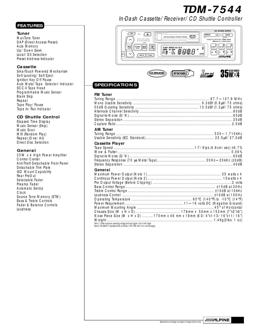
Alpine TDM-7544 Specifications

Alpine

Alpine TDM-7544 Specifications

JL Audio Stealthbox SB-CAN-G2MVX3D/10TW3 installation guide

JL Audio

JL Audio Stealthbox SB-CAN-G2MVX3D/10TW3 installation guide

Denso TEN FT0108A user manual

Denso TEN

Denso TEN FT0108A user manual

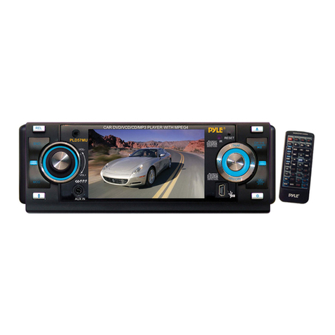
Pyle PLD57MU owner's manual

Pyle

Pyle PLD57MU owner's manual

Harman Chrysler Radio Navigation System RB4 user manual

Harman

Harman Chrysler Radio Navigation System RB4 user manual

Sony MEX-BT5750U operating instructions

Sony

Sony MEX-BT5750U operating instructions

manuals.online logo
manuals.online logoBrands
  • About & Mission
  • Contact us
  • Privacy Policy
  • Terms and Conditions

Copyright 2025 Manuals.Online. All Rights Reserved.

CD037RMP
-1-
NO.
29
PARTS NO.
SERVOCD037V2
DESCRIPTION
SERVO PCB
Q’TY
1
Service Manual
Xiamen Clarion Electrical Enterprise Co., Ltd
8/F., Xiamen Mail Processing Centre, No.275 Lujiang Road, Xiamen, China
Tel:+86-592-2389080 Fax:+86-592-2389089
Clarion Co., Ltd.
50 Kamitoda, Toda-shi, Saitama 335-8511 Japan
CD/USB/MP3 Receiver
Model
CD037RMP
NOTE
* Specifications and design are subject to change without notice
for further improvement.
Published by Service Dept.
298-6400-37-02 (GEN. 2009)
Printed in P.R.C.
ORIGINAL SERVICE MANUAL
This additional service manual is designed to be used
together with Original Model CD037RMP
DIFFERENCE
EXPLODE VIEW .PART LIST
Switch DCP Section/Main Section
(Refer to page 10 of the original
service manual)
DIFFERENCE
ELETRICAL PARTS LIST
Main PWB Section
(Refer page 11 to 14 of the original
service manual)
DIFFERENCE FROM ORIGINAL
MODEL
1. EXPLANATION OF IC
2. PART LIST
Switch DCP Section
Main Section
3. ELETRICAL PARTS LIST
Main PWB Section
4. PRINTED WIRING BOARD
Section CD MECHANISM
5. PRINTED WIRING BOARD
Main PWB section
6. CIRCUIT DIAGRAM
Section CD MECHANISM
7. CIRCUIT DIAGRAM
Main PWB Section
Original Model Manual No.
298-6400-37-00
CD037RMP
PART. No.
0010RF881703100
017WWOR150TSC00
377R140125B0000
37814125120MU00
Description
MCU RF8817-031
LED Red
FPC/FFC Connector 14
FFC 14 pin
REF. No.
IC201
LED202
CON1
CON1
CD037RMP
-2-
EXPLANATION IC
PIN FUNCTION
DOCUMENT No: RF8817-0x1
PIN P-NAME I/O Act DESCRIPTION When not Used REMARK
1 BT_OUT
DIO IN4
O
I
H Bluetooth Audio Control Output.
Option diode input 4.
Open
2 IPOD_O
DIO IN3
O
I
H iPod Audio Control output.
Option diode input 3.
Open
3 DIOO3 O H Optional diode output 3
4 DIOO2 O H Optional diode output 2
5 DIOO1 O H Optional diode output 1
6 RESET HD L To start u-COM,
High input should be triggered with high input.
3.2V reset is recommendable.
7 3 COLOR
/DIO IN2
O H 1. 3 COLOR output for front illumination.
2. Option diode input 2.
8 2 COLOR
/ALARM
/DIO IN1
1. When front opened, the output is generated
per 1sec. with 10% duty (LOW=LED on).
With this port, a flashing LED is used.
2. When power is on, by pressing the {DISP}
key for more than 1sec. the output is toggled.
With this port, the switching of 2 color lamps can
be used.
3. Option diode input 1.
Refer to
the circuit
9 FLMD0 HD H This is a pin for setting flash memory programming
mode.
Connect FLMD0 to GND in the normal operation
mode.
In flash memory programming mode, connect this
pin to the flash programmer.
Series resister 4.7Kohm is needed to GND.
10 X-IN HD 7.2 MHz X-TAL INPUT
11 X-OUT HD 7.2 MHz X-TAL OUTPUT
12 REGC HD Regulated Voltage output Open
13 GND HD Ground.
14 GND HD Ground.
15 VDD HD VDD 5V DC
16 VDD HD VDD 5V DC
17 TOUCH_
DAT
O Data in/out from/to Touch Sensor(DT8800)
Direct Connect with Pin50
Open
DRAIN
18 TOUCH_
ALBEN
I/O Control output to DT8800.
Direct Connect with Pin49
Open
DRAIN
CD037RMP
-3-
PIN P-NAME I/O Act DESCRIPTION When not Used REMARK
19 VR CLK O E.VR Communication CLK OUT
Needed pull up resistor(2.2K) from switch 5Vdc.
Open Open
DRAIN
20 VR DATA O E.VR Communication DATA OUT
Needed pull up resistor(2.2K) from switch 5Vdc.
Open Open
DRAIN
21 SD_DET
/DIO IN12
I L 1. SD Detection Input.
2. Option diode input 12.
22 F_INH O H FRONT Communication INH output.
23 F_DATA I/O FRONT LCD driver Communication data.
24 F_CLK I/O FRONT and LED driver Communication clock.
25 F_CE O H Front Communication Chip Enable.
26 TEF_SCL
PLL_CLK
/STIN
I/O
O
I
1.Clock output to TEF6606 Tuner
2.PLL IC Communication CLOCK OUT.
3.ST input. Low=Stereo.
Series 2.2Kohm to STIN must be added.
Pull up
27 TEF_SDA
PLL_CD
I/O
O
1.Data out/in to TEF6606 Tuner
2.PLL IC Communication DATA INPUT/OUTPUT
28 PLL_CE O PLL IC Communication CHIP ENABLE
29 LOCAL O H Radio LOCAL output during seek(Loc=High)
30 CDPRST O L Reset the DSP and ASP in CDP. Open
31 CDPO O H At CDP mode H is output.
32 USB_DET I L USB Detection Input
33 REMOCON I Remote control input.
The power supply of Remote receiver is to be
turned off during ACC off.
Pull Down
1M
34 SYSTEM
POWER
O H When radio is power on (High=power on).
This port is to control power on of the system.
35 MUTEOUT O L Mute output for power IC(LOW=MUTE)
36 FEEDF O H FEED Motor Forward in single CDP. Open
37 FEEDR O H FEED Motor Reverse in single CDP. Open
38 CDC BUS
TOUCH_
CLK
I/O CD CHANGER Communication BUS Input
Pull down resistor(1M) should be connected.
A zener diode (5.6V) to GND is recommendable
to protect from a outside surge.
Add series 220ohm to protect port.
Clock in/out from/to Touch Sensor(DT8800)
Pull
Down
Pull Down
1M
39 RDS DATA I RDS Data Input in RDS Model. Pull up
40 {RDS CLK}
I/O H RDS Clock Input GND Pull Down
1M
CD037RMP
-4-
PIN P-NAME I/O Act DESCRIPTION When not Used REMARK
41 B_UP
I L 1. ACC ON Detection input. (Low=system halt).
To detect rapidly, standard circuit is
recommendable
described in hardware application note.
Refer to
the circuit
42 BT_RXD I Bluetooth RXD Input.
43 BT_TXD O Bluetooth TXD output.
44 IPOD_DET I H IPOD detection input for connection input. Pull down 220k
45 NC I Reserved for future use. Pull up
46 AF MUTE O H RDS AF MUTE output.(High=Mute).
47 VDD HD VDD 5V DC.
48 GND HD Ground.
49 KEYADI2 I AD KEY INPUT2.
Must be pulled up with 4.7Kohm from AVREF
in MAIN PCB.
AD input
50 KEYADI1
/FRT DET
I Key A/D input1 and front detect input.
Must be pulled down with 1Mohm in main PCB.
Must be pulled up with 4.7Kohm from AVREF
in front PCB.
AD input
51 DANCE3 I Level dancing input3 (ex: 10kHz) GND AD input
52 DANCE2 I Level dancing input2 (ex: 1kHz) GND AD input
53 DANCE1 I Level dancing input1 (ex: 100Hz) GND AD input
54 S-METER I Connected to S-METER output of IF ICs. AD input
55 TEL/CDSW I 1. TELPHONE MUTE INPUT(4.54~5.0 Vdc)
2. S-cdp switch input.
Must be pulled up with 47Kohm from AVREF.
Must be pulled down with 330Kohm to AGND.
AD input
56 ENCODER I Encoder volume input.
Pull up 47Kohm from AVREF and Pull-down
330Khom to GND.
Series 82Kohm to VOL B.
Series 47Kohm to VOL A/C.
GND Refer to
the circuit
57 SAT_PW
DIO IN11
I H 1. High output in XM mode for XM power.
2.Option diode input 11.
58 MP3_CK
/DIO IN10
O 1. MP3 Communication CLK output.
2. Option diode input 10.
59 MP3_DI I MP3 Communication data output.
Needed pull up 220ohm from CDP powered 5V.
60 MP3_DO
/DIO IN9
O 1. S-CDP/MP3 Communication data output.
2. Option diode input 9.
CD037RMP
-5-
PIN P-NAME I/O Act DESCRIPTION When not Used REMARK
61 MONO
/AUX OUT
/DIO IN8
O H 1. Forced mono control output (High=mono).
2. AUX output (High = AUX mode).
3. Option diode input 8.
Open
62 MP3_REQ
/DIO IN7
I L 1. MP3 request input from MP3 module.
2. Option Diode input7.
63 BEEP
/FUNC
/DIO IN6
O 1. BEEP SOUND OUTPUT
It should be connected with the normal audio
signal.
Unless special requirement, it is recommended to
be
connected to front CH of audio signal.
2. FUNC OUT (FUNC=HIGH)
3. Option diode input 6.
64 SENS1_O
/DIO IN5
O H 1. For the optical loading S/W,
Connect to the Anode of loading sens LED of CDP
with TR for AUTO POWER ON
2. Option Diode input 5.
CD037RMP
-6-
DIFFERENCE
PRINTED WIRING BOARD
Section CD MECHANISM 1/2
CD037RMP
-7-
DIFFERENCE
PRINTED WIRING BOARD
Section CD MECHANISM 2/2
CD037RMP
-8-
DIFFERENCE
PRINTED WIRING BOARD
Main PWB section 1/2
CD037RMP
-9-
DIFFERENCE
PRINTED WIRING BOARD
Main PWB section 2/2
CD037RMP
DIFFERENCE
CIRCUIT DIAGRAM
Section CD MECHANISM 1/1
-10-