U-PAD2 A/D Converter Table of Contents
Contents
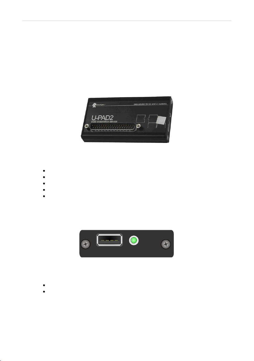
1 U-PAD2 acquisition device 1
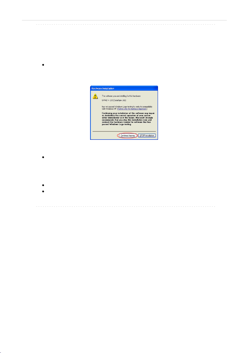
1.1 Side panel of the U-PAD2 device 1
1.2 A/D converter types in general 1
2 Requirements 3
3 Installation 4
3.1 The U-PAD2 4
3.2 Standard cable for Clarity station 6
3.3 Connection with chromatograph 7
3.3.1 Connection of signal cables 7
3.3.2 Connection of starting cables 8
3.4 Clarity Configuration 9
3.4.1 Measuring on multiple instruments 11
3.4.2 Using multiple U-PAD2 converters 12
4 Using the U-PAD2 13
4.1 DataApex U-PAD2 Setup 13
4.2 Method Setup 16
4.2.1 Method Setup - Acquisition 16
4.2.2 Method Setup - Measurement 18
4.3 Digital Inputs and Outputs 19
4.4 Device Monitor 20
5 Troubleshooting 21
5.1 Locate your problem 21
5.2 Problems with U-PAD2 22
5.2.1 How to check the U-PAD2 driver 23
5.3 Manual installation 25
5.3.1 Installation and reinstallation in Windows XP and later 25
5.3.1.1 Reinstallation of drivers using the System Restore Point 28
5.3.2 Reinstallation of drivers in Windows 2000 29
5.3.2.1 Deleting incorrect *.INF files in the system 29
5.3.2.2 Installing the correct driver manually 30
5.4 Data Acquisition - non-functional 33
5.5 Data Acquisition - Simulated 35
6 Tables and specifications 36
6.1 Description of the INT7 connector (Male) 36
6.2 Parameters of digital inputs and outputs 37
6.3 U-PAD2 - CE conformity declaration 38
6.4 Technical Data 38
- i -