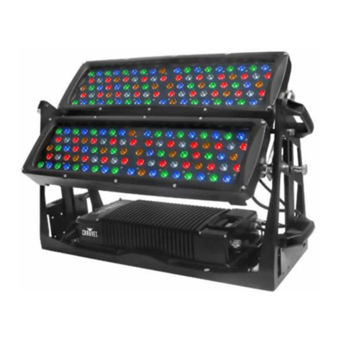
CLARIUS EP PLUS IEP-810 User manual

Clarius EP PLUS
LED FLOODLIGHT
Installation Guide
CERTIFICATION: SIRA09ATEX5159X AND IECEx SIR 09.0064X AND ABS 11-LD801943-PDA
II 2 G D Ex emb IIC T4 Gb Ex t IIIC T103oC Db IP66/67 T4 -20 oC to +50 oC
CONTENT
1. SAFETY INSTRUCTIONS
2. INSTALLATION
3. MAINTENANCE
4. TECHNICAL SPECIFICATION
5. TROUBLE SHOOTING
IMPORTANT INFORMATION
The Clarius EP Plus series of explosion protected oodlights are specialist devices, certied for use in
hazardous gas and dust operating environments.
The units must be installed in accordance with these instructions, must be correctly certied for the
specic operating environment and must be installed by suitably qualied personnel.
If you have any queries about the installation or the certication of the unit – please contact GJD for
immediate assistance and advice.
Unit 2 Birch Business Park, Whittle Lane, Heywood, Lancashire, OL10 2SX
www.gjd.co.uk [email protected] +44 (0) 1706 363 998
Clarius®

1. SAFETY INSTRUCTIONS
1. Read this leaet carefully before commencing to install the Clarius EP Plus unit and retain it for future
use. Installation can only be carried out by suitably qualied personnel.
2. Check the certication nameplate attached to the oodlight to ensure that the mains supply and
the ambient temperature present is suitable for the unit being installed.
3. If the Clarius EP Plus unit is to be installed in areas of high vibration, please consult with GJD.
4. The Clarius EP Plus unit housing is constructed from marine grade aluminium and polycarbonate. The
end user must ensure that these materials are suitable for the atmosphere the Clarius EP Plus unit will
be installed in.
5. The temperature rise on the incoming mains cable is 61oC above the ambient conditions. Select
suitable cable and ATEX/IECEx cable glands. For advice on suitable glands and cables, please con
tact GJD. All unused entries must have a suitable approved stopper plug tted.
2. INSTALLATION
MOUNTING Clarius EP Plus UNIT
1. To meet the requirements of certication a MINIMUM of two xing points must be used. The xing
points must be suitable for the conditions of use. The drawing below shows horizontal mount, single
unit. For multiple mounting brackets and other mounting options please contact GJD.
www.gjd.co.uk

Tel: +44 (0) 1706 363 998
2. The unit may have been ordered and supplied with an integrated photocell. Care should be taken
when positioning the unit to ensure the sensor is not shielded, is not pointing directly at another light
source and is monitoring the general, prevailing light conditions.
3. The mounting bracket for the Clarius EP Plus oodlight is packed separately in the carton. The bolts in
the side of the housing shall be removed and used to secure the bracket to the Clarius EP Plus
housing. It is very important that the red bre washers are tted between the Clarius EP Plus housing
and the mounting bracket. The unit must be aligned rst before securing the bracket. The unit can
be mounted horizontally or vertically allowing the unit to point up/down or left/right, 2 additional
holes allow the bracket/fasteners to be moved to suit mounting application. An external eye bolt is
supplied to allow safety chains/suspension cords to be tted if required.
POWER CONNECTIONS
4. Wire the Mains cable into the terminal block. Provision has been made for this and identied as the
E (Earth), L (Live) and N (Neutral) terminals. There are two pairs of contacts for each of these to
facilitate a mains cable that can be looped in and out of the unit.
5. The installer should earth the unit separately.
6. Connect wires to mains supply; Blue=neutral: Brown=Live: Green/Yellow=Earth
7. Isolate the unit before opening.

www.gjd.co.uk
ADDITIONAL IMPORTANT INFORMATION
Note: Torque = Newton Meter (Nm)
8. All Clarius EP Plus units have terminal blocks suitable for 4mm2 live, neutral and earth.
9. To maintain an IP rating of 66/67 All M6 socket head cap bolts xing the
polycarbonate lid to the enclosure shall be tightened down to 2.5 Nm.
10. When installing the unit the special conditions for safe use should be adhered to –
i. Except for internal wiring, not more than one single or multiple strand lead shall be
connected into either side of any terminal unless multiple conductors have been joined in
a suitable manner, e.g. two conductors into a single insulated crimped boot lace ferrule.
ii. Leads connected to the terminals shall be insulated for the appropriate voltage and this
insulation shall extend to within 1 mm of the metal of the terminal throat.
iii. When terminals in accordance with certicate Sira 01ATEX3247U are used, all terminal
screws, used and unused, shall be tightened down to between 0.5 Nm and 0.7 Nm.
iv. When terminals in accordance with certicate Sira 01ATEX3249U are used, all terminal
screws, used and unused, shall be tightened down to between 1.2 Nm and 2 Nm.
v. When terminals in accordance with certicates Sira 01ATEX3247U and Sira 01ATEX3249U
are used, they shall only be installed and wired with cable within a temperature range of
-10°C to +80°C.
vi. When cross-connecting combs are used on terminals to certicates Sira 01ATEX3247U and
Sira 01ATEX3249U, the relevant conditions certication associated with those certicates
shall be applied.
vii. Cable entry holes shall be tted with either an appropriately certied cable gland or
appropriately certied blanking element. These shall provide and maintain a minimum
enclosure ingress protection of IP66 or IP67 as appropriate.
viii. If more than 8 individual LED’s are not illuminated the LED assembly must be replaced.
ix. When the optional fuse is not tted, the supply circuit must be protected by a fuse capable
of withstanding a prospective short circuit current of 1500A

Tel: +44 (0) 1706 363 998
3. MAINTENANCE
1. Isolate the Clarius EP Plus unit from the mains supply and allow it to cool before carrying out
any maintenance work.
2. In the unlikely event of the failure of a string of LED’s (6 or 8), the assembly must be re
placed. Contact GJD for immediate assistance and advice.
3. It is essential that all Clarius EP Plus units are maintained in accordance with the
requirements of the EN60079-17 standard: Electrical apparatus for explosive gas
atmospheres – other than mines.
4. IMPORTANT! No modications are permitted to the unit. All spare parts must be purchased
from the manufacturer or authorized distributor. Any unauthorized modications or spare
parts may make the apparatus dangerous and invalidate certication.
5. ELECTROSTATIC CHARGING HAZARD - Plastic components may be cleaned with water
containing a small amount of detergent, followed by a clean water wash. Surplus water
can be wiped off plastic components, but they should not be wiped or polished with a dry
cloth to avoid a build-up of static electricity. Strong cleaning solvents could cause damage
to plastic components.
6. Disposal of packaging, Clarius EP Plus units and old LED assemblies should be carried out in
accordance with national regulations.
4. TECHNICAL SPECIFICATION
CERTIFICATION
II 2 G D Ex emb IIC T4 Gb SIRA09ATEX5159X
Ex t IIIC T103°C Db IP66/67 IECEx SIR09.0064X
Ta = -20°C to +50°C ABS 11-LD801943-PDA
Clarius EP Plus SPECIFICATION
Input Voltage 24V AC/DC or 100-240V AC
Consumption 60W max
Power Factor >0.95 or better
Mains Frequency 50/60Hz
IP Rating 66/67
Single Unit Weight 6Kg per module
Dimensions 250 135 x 315mm
ATEX and IECEx Rating Zone 1 gas and dust hazardous environments

Unit 2 Birch Business Park, Whittle Lane, Heywood, Lancashire, OL10 2SX
www.gjd.co.uk [email protected] +44 (0) 1706 363 998
Ordering codes Clarius EP Plus Floodlight
MODEL NUMBER WAVELENGTH ANGLE DISTANCE FOV
IEP-810 850nm 10 150m 492ft 26m 85ft
IEP-830 850nm 30 80m 262ft 42m 137ft
IEP-860 850nm 60 56m 184ft 64m 210ft
IEP-810-PC 850nm 10 150m 492ft 26m 85ft
IEP-830-PC 850nm 30 80m 262ft 42m 137ft
IEP-860-PC 850nm 60 56m 184ft 64m 210ft
MODEL NUMBER ANGLE DISTANCE FOV
VEP-CW10 10 120m 394ft 21m 69ft
VEP-CW30 30 65m 262ft 34m 111ft
VEP-CW60 60 45m 184ft 52m 170ft
VEP-CW10-PC 10 120m 394ft 21m 69ft
VEP-CW30-PC 30 65m 262ft 34m 111f
VEP-CW60-PC 60 45m 184ft 52m 170ft
Infra Red
White Light
Please contact GJD for alternative mounting options, voltages, colour of LEDs etc.
Multiple units are also available.
5. TROUBLE SHOOTING
1. Ensure the two LED boards are correctly wired to terminal block.
Red to Red: Black to Black
2. Ensure Mains input is correctly connected.
Earth to Yellow/Green: Live to Brown: Neutral to Blue
3. Ensure Mains Input is turned on at the source.
This manual suits for next models
11
Table of contents
Other CLARIUS Floodlight manuals
