CLARIUS DUO PLUS Series User manual

Infrared & White Light LED Illuminators
• Dual Core®Technology
• Interchangeable Lens Diffuser Technology
Step 1: Select bracket Step 2: Place bracket
at to wall
Step 3: Drill appropriate
holes and secure xing
screws safely
Step 4: Mount the
Illuminator unit securely
to the bracket using
the Allen key provided
Step 5: Loosen bolts
top and bottom to
adjust the illumination
coverage
Step 6: Select the diffuser angle sheet
required from Clarius Box (if required).
To position the required diffuser sheet,
insert the tool included in the slot at
the bottom of the cover and prise
upwards slowly. Repeat at opposite
end and carefully remove cover.
Remove backing sheet from the two
adhesive discs and secure required
diffuser in position. Finally, clip both lens
covers back into place.
Narrow Angle Wide Angle
Step 7: Adapt the illumination of the illuminator (if required).
PSU Features
The IP66 Clarius range of constant current LED lighting Power Supply Units have
been designed to power the Clarius range of LED lighting products. They feature a
regulated current output that can be adjusted by the installer to set the brightness
of the Illuminator to suit the application. The unit has an integral photocell (dusk/
dawn sensor) that can be adjusted to automatically turn the Illuminator on at a
pre-determined light level. A trigger input connection allows for the output to be
overridden (turned on) from a remote source and an on board relay can be used
to switch a day/night camera between operation modes. The universal mains
input voltage allows the power supply to be used across a wide geographical area
while the highly efcient switch mode design ensures low operating costs and cool
running. They are available in two power variants, providing enough power to drive
multiple units as necessary.
• Available in 3.2A or 4.6A versions
• High Efciency switch mode technology
• IP66 design for outdoor use
• Supplied with IP-rated cable glands
• Light Sensor
• Universal mains input voltage 90-264Vac
• Short Circuit, Overload, Over temperature
and Over Voltage protection
• Variable illumination preset
• Operating Temperature: -10°C to +40°C
PSU User Connections & Adjustments
Connections:
1) Mains Input
2) LED Output 1
3) LED Output 2
4) Remote Input
5) Relay Output
6) Photocell Input
Potentiometers:
7) User Light O/P level
8) Photocell Lux Level
LED:
9) Diagnostic LED
Clarius® DUO PLUS
IRWL
Unit 2 Birch Business Park, Whittle Lane, Heywood, Lancashire, OL10 2SX
www.gjd.co.uk [email protected] +44 (0) 1706 363 998
Clarius®
LED Illuminators
Infrared & White Light LED Illuminators
Product Code Wavelength Angle Distance FOV
IL2-8 850nm
10º - Circular
20º - Elliptical
30º - Elliptical
60º - Elliptical
80º - Elliptical
95º - Elliptical
319m
218m
160m
102m
73m
51m
1048’
714’
524’
333’
238’
167’
56m
77m
86m
117m
122m
111m
183’
252’
281’
385’
400’
364’
IL2-9 940nm
10º - Circular
20º - Elliptical
30º - Elliptical
60º - Elliptical
80º - Elliptical
95º - Elliptical
196m
137m
111m
68m
51m
34m
643’
448’
364’
224’
168’
112’
34m
48m
59m
79m
86m
75m
113’
158’
195’
259’
282’
245’
Product Code Wavelength Angle Distance FOV
IX2-8 850nm
10º - Circular
20º - Elliptical
30º - Elliptical
60º - Elliptical
80º - Elliptical
95º - Elliptical
367m
250m
183m
117m
83m
58m
1202’
820’
601’
383’
273’
191’
64m
88m
98m
135m
140m
127m
210’
289’
322’
442’
459’
418’
IX2-9 940nm
10º - Circular
20º - Elliptical
30º - Elliptical
60º - Elliptical
80º - Elliptical
95º - Elliptical
225m
157m
127m
78m
59m
39m
738’
514’
418’
257’
193’
129’
39m
55m
68m
91m
99m
86m
129’
181’
224’
297’
324’
281’
Product Code Angle Distance FOV
VL2-CW
10º - Circular
20º - Elliptical
30º - Elliptical
60º - Elliptical
80º - Elliptical
95º - Elliptical
195m
130m
114m
81m
65m
49m
639’
426’
373’
266’
213’
160’
34m
46m
61m
94m
109m
106m
112’
150’
200’
307’
357’
349’
Product Code Angle Distance FOV
VX2-CW
10º - Circular
20º - Elliptical
30º - Elliptical
60º - Elliptical
80º - Elliptical
95º - Elliptical
223m
149m
130m
93m
74m
56m
733’
489’
428’
305’
244’
183’
39m
53m
70m
108m
125m
122m
128’
172’
229’
353’
410’
400’
PSU Installation, Set-up & Operation
Mounting:
Mount the power supply on a sound surface using appropriate
xings for the installation, mounting screw locations are located
within the lid screw apertures – these must be used to retain the
enclosure IP66 rating. Route mains cable though left hand M16
cable gland, the three M12 cable glands are used for the LED
power O/P’s and the remote input / output contacts (if used).
Note: Any unused glands must be ‘plugged’ with supplied
blanks and tightened to ensure IP66 protection.
Connections:
Attach correctly rated mains cable (minimum 0.5mm² [3A],
300/500Vac) to the mains input connection. Connect the
illuminators to the LED Output 1 & 2 connections, there are 2
available to assist with connecting multiple units – note polarity.
The remote input is triggered by connecting the input to 0V by
a suitable N/C contact. The Remote Output ‘follower’ contact
provides a N/C output when the output to the illumination
unit(s) is in the ‘ON’ state, going N/O when power is removed.
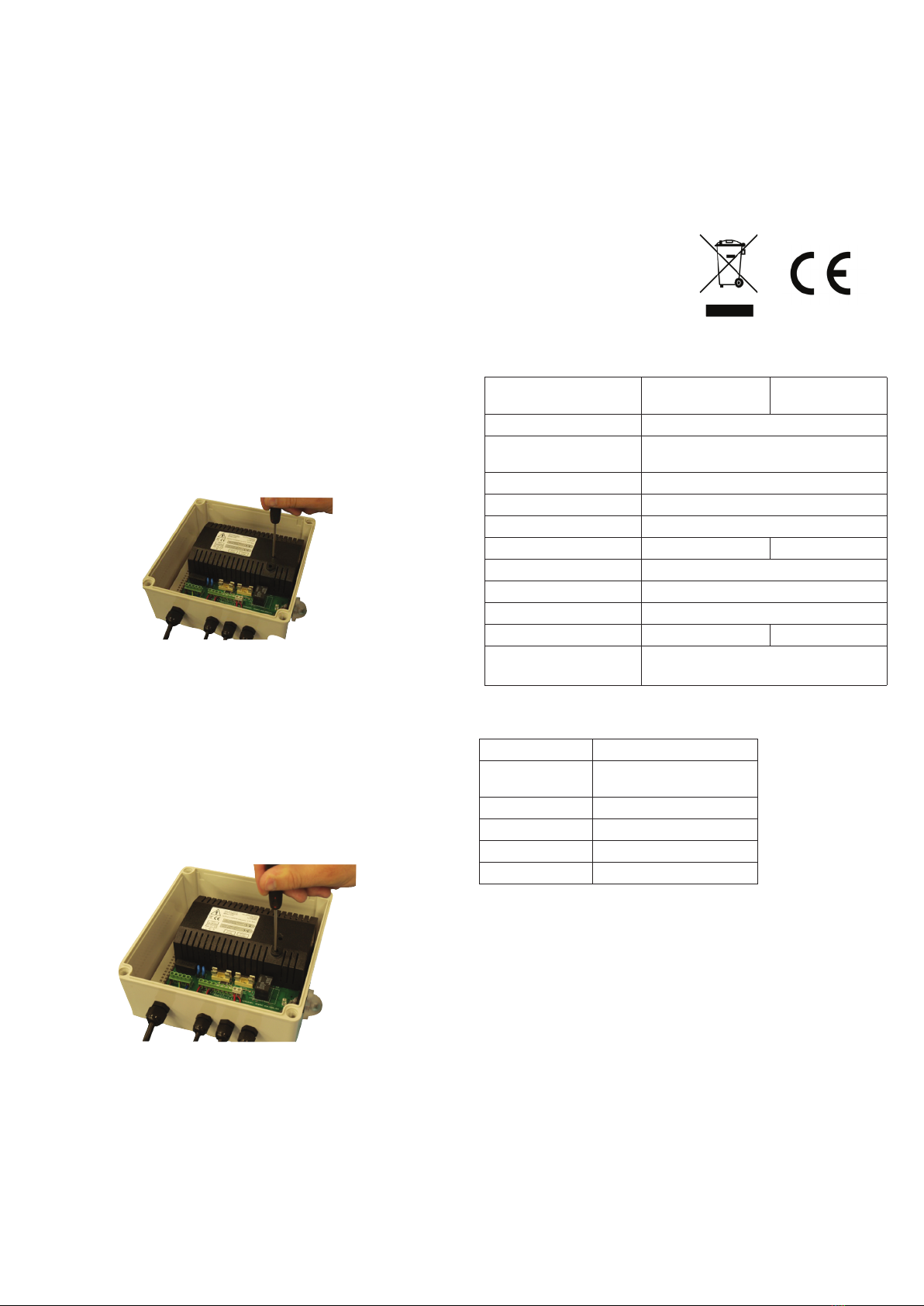
Output Current Adjustment (Brightness):
Brightness of the illuminators can be adjusted by the user output
current adjustment potentiometer Turning the pot clockwise
using a small terminal screwdriver will increase the current (LEDs
brighter), turning anticlockwise will reduce the current and
therefore decrease the brightness of the illumination. Note: DO
NOT force the potentiometer past its end points.
Setting ‘Switch-on’ Lux Level:
By adjusting the Lux Level potentiometer, the installer can
set the external light level at which the PSU will switch on the
illumination unit(s). Turning the pot clockwise using a small
terminal screwdriver will increase the light level required before
the unit turns on, anticlockwise will reduce the light level
required. Setting the pot fully anti-clockwise will set the output
to be on continuously while setting the potentiometer fully
clockwise (indicated by the status LED ashing briey) will set
the PSU to ‘Remote Input’ mode where the unit will only turn
on with the remote input activated. Note: DO NOT force the
potentiometer past its end points.
The unit is only suitable for installation as permanently
connected equipment. EQUIPMENT MUST BE EARTHED. Before
installation, ensure that external disconnect device is OFF.
The PSU should be installed according to all relevant safety
regulations. The unit is intended for use by Service Personnel
only - There are NO USER SERVICEABLE parts inside. There is no
regular maintenance required of the PSU, if the output of the
PSU fails, the cause of the failure should be investigated e.g.
short circuit load. The fault should be rectied before restoring
power to the PSU.
Disposal of product at end of life
This product falls within the scope of EU Directives 2002/96/
EC Waste Electrical and Electronic Equipment (WEEE). At the
end of life, the product must be separated from the domestic
waste stream and disposed via an appropriate approved
WEEE disposal route in accordance with all national and local
regulations. The packaging supplied with this product may be
recycled.
Please dispose of packaging accordingly.
This product meets the essential requirements of the following
EU Directives:
Low Voltage: 2006/95/EC
EMC: 2004/108/EC
WEEE: 2002/96/EC
RoHS: 2011/65/EU
Compliance
PSU Technical Specifications
Model ALT-PSU2-L
IL2-8/VL2-CW
ALT-PSU2-X
IX2-8/VX2-CW
Input Voltage (Rated) 100-240Vac
Input Voltage
(Operating)
90-264Vac
Frequency 50-60Hz
Max Input Current 2.0A (Max)
Mains Input Fuse T3.15A
Output Current 3.2A 4.6A
Voltage range (max) 17-24Vdc
Efciency (Typ) >82%
Ripple 150mV pk-pk (max)
Output Fuse (Load) 2 x F1.6A 2 x F2.5A
Overload Electronic Shutdown overload until
overload or short circuit removed
IP Rating IP66
Dimensions(Lx-
WxH) 200x200x100m
Weight 1.35kg
Operating Temp -10ºC to +40ºC
Storage Temp -20ºC to +80ºC
Warranty 3 Years
PSU Mechanical /Environmental
This manual suits for next models
6
Popular Spotlight manuals by other brands


Larson Electronics
Larson Electronics HL-85-LED-CPR-NC instruction manual

Heitronic
Heitronic DL7002 Installation and operating instructions

NORDRIDE
NORDRIDE 4350-100A operating instructions

Eurotops
Eurotops 46593 instruction manual

Altman
Altman PHX Series user manual

Varytec
Varytec LED Theater Spot 50 3200K user manual

DTS
DTS XR700 SPOT user manual

Renkforce
Renkforce 1170824 operating instructions

Cooper Crouse-Hinds
Cooper Crouse-Hinds SFA6 Installation & maintenance information

Ansorg
Ansorg Navo NSK DDF instructions

Lightforce
Lightforce Enforcer 140 LED instructions

thomann
thomann Ignition 2bright Pint FC150 IP user manual