Clark-Reliance Levalarm EA100 Series Instruction Manual

InstructionsforInstallingandOperatingClark‐
RelianceEA100SeriesLevalarm®
Thismanualcoversthefollowingmodelnumbers:EA100D,EA100S,EA100SW,EA100DP,EA100SP,
EA100DRPT,andEA100SRPV
Section: R500.532F
Bulletin: 532F
Date: 7/1/2015
Supersedes: 532E
16633 Foltz Parkway, Strongsville, OH 44149 USA
Telephone: (440) 572-1500 Fax: (440) 238-8828
www.clark-reliance.com

STORAGE and HANDLING
All units should be inspected upon receipt to ensure that no damage has been incurred during transit.
If there is a claim due to damage, it should be filed with the carrier immediately. Clark-Reliance Boiler
Trim products should be stored in a dry and sheltered area prior to installation. The equipment
provided may consist of electrical items that are intended for either indoor or outdoor use. As a matter
of good practice, dry storage will prevent the products from exposure to the outdoor elements. This
will eliminate the potential for water damage. The temperature of the storage area should not exceed
150 Deg. F (84 Deg. C) or drop below 32 Deg. F (0 Deg. C).
OPERATION
A stainless steel float swings at the end of a pivot rod. The rod head carries an Alnico V magnet. The
magnet attracts one leg of a U-shaped armature which is attached to a micro switch leaf actuator. A
buoyed float holds the switch open or closed, depending on which terminals are used. As liquid falls
in the chamber, the float drops and directs the magnet to the opposite position. A closed switch
actuates alarms. An open switch achieves fuel cut-out.
INSTALLATION
Caution: Before proceeding, follow any and all plant lock out - tag out procedures required. Verify
that all power is turned off to the Levalarms. If under pressure, the equipment should be isolated, or
the boiler should be shut down before proceeding with the installation. Open drain valve to eliminate
any trapped pressure. All inspection and installation steps should be performed by a qualified
technician and should be executed in accordance with all applicable national and local codes
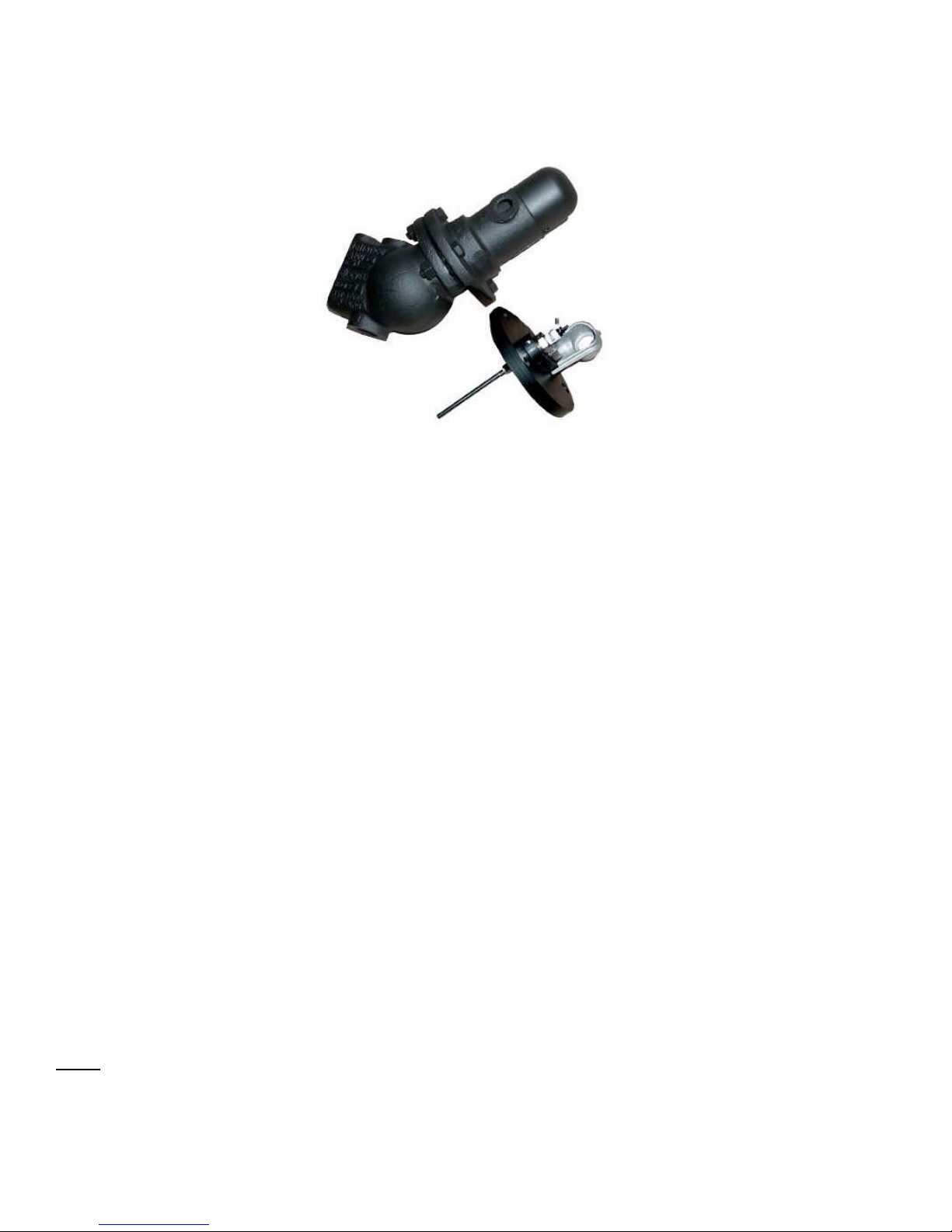
EA100 Series Levalarm dimensional information.
(Please refer to applicable drawing for component information.)

Standard connections for the EA100 Series Levalarms are 1” FNPT for threaded connections or 1”
FSW for socket weld connections. The Levalarm should be installed with the reference arrow (switch
point) at the level where the alarm or trip is specified. Shut off valves above and below the Levalarm
should be installed for safe inspection or repair of the unit. However, these valves must be locked
open when the boiler is in service.. Also, a drain connection with a shut off valve should be installed
to a point of safe discharge to facilitate blowdowns. Below is a typical arrangement for the installation
of the Levalarm.
After the piping has been installed to the body of the Levelarm, the switch should connected by
following this procedure:
1. Remove the switch cover in order to access the connections on the switch assembly by
loosening the screw ot the bottom of the dome shaped cover.
2. Use the 7/8” Dia. opening in the switch housing assembly for connecting flexible or rigid
conduit when wiring the unit.
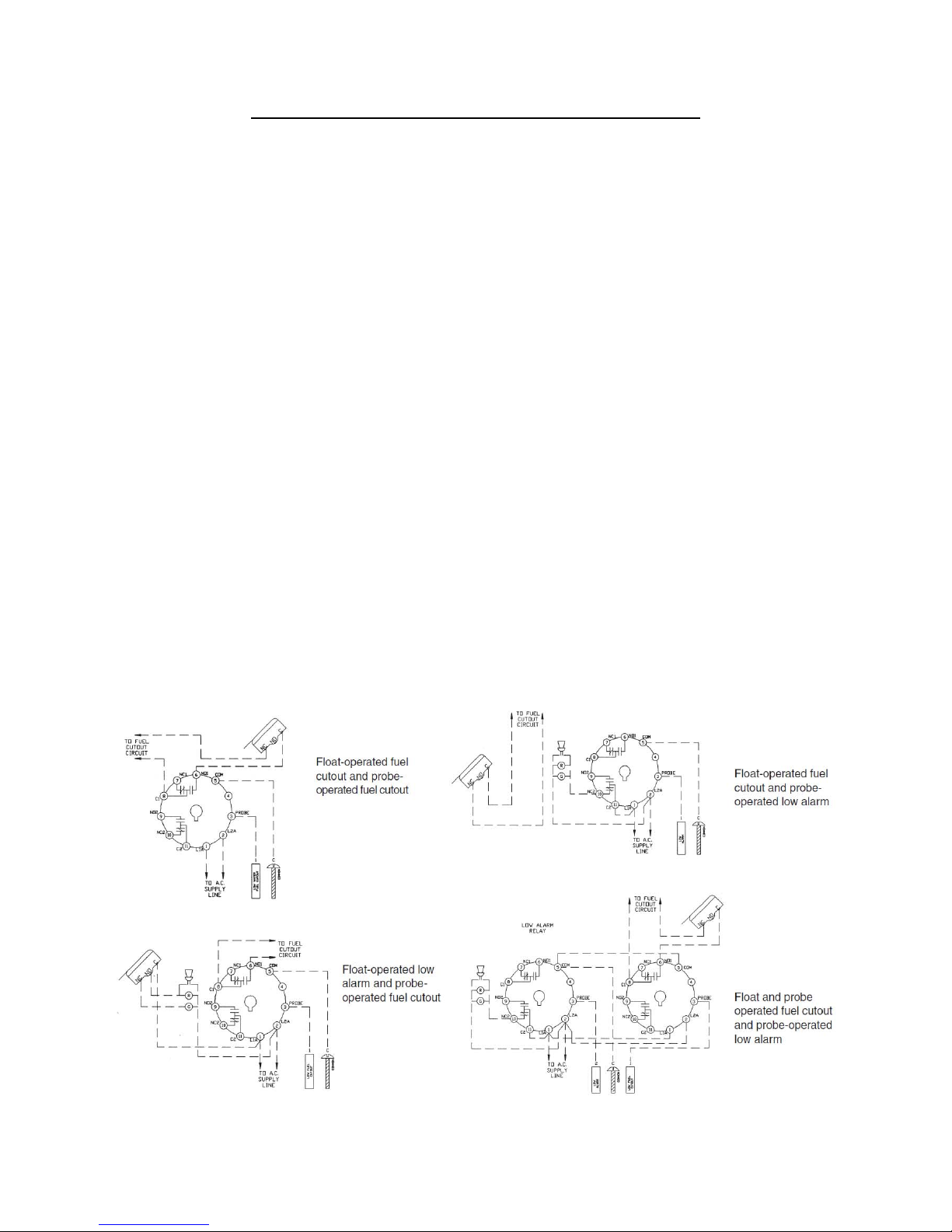
3. Example wiring diagrams for connectiong the low water cutout, alarms (such as lights or and
audible signal), etc, are illustrated below.
4. After checking that all connections are tight and correct, replace the switch cover, as the unit is
now ready do be put in operation.
LowWaterCutoutLevel
Note:Somejurisdictionsdonotpermitthe
installationofisolationvalvesasshown.
ConsultapplicableCodesbeforeinstallation.

CAUTION: Make sure that all wire leads to the switch do not interfer with the operation of the switch
actuator before replacing the switch cover!
NOTE: It is recommended that periodic inspection and routine maintenance be conducted to ensure
that the Levalarm continues to work properly. This can be conducted by following the procedure:
1) Isolate the Levalarm by closing the steam and water isolation valves.
2) Open the drain valve to drain the unit and relieve any internal pressure.
3) Remove the switch cover, disconnect the wiring and the conduit.
4) Using a ¾” wrench or socket for the bolt and a 7/8” wrench or socket for the nut, remove the
nuts on the flanged cover (4 nuts on the EA100D and 6 nuts on the EA100S/EA100SW).
Discard old gasket.
5) Removing the flange provides complete access to the float and switch assembly.
6) Inspect the float to make sure that water has not leaked directly into the float.
7) Check to make sure the float and pivot rod assembly freely moves up and down and does not
stick or bind.
8) Inspect the magnet tube to make sure there is no contamination in the tube or attached to the
magnet itself.
9) After the inspection is complete, re-assemble the flanged switch assembly to the body using a
new part number C1-3 gasket. The gasket may be held in place by applying a silicone based
pipe joint compound onto the flange gasket surface. Make sure the flange unit is oriented
properly.
10)Lubricate the threads on the bolts with a high temperature nickel based lubricant. Torque the
bolting in the proper sequence (see below) to 70 ft-lbs in 1/3rd increments.
11)Re-install the conduit and the wiring.
Bolt Torqueing Pattern:
MODELS WITH PROBES - EA100DP AND EA100SP
For Levalarms with optional probes, follow this procedure after piping has been connected to body of
the unit:
1. Install relay control unit at any convenient location, as the connecting wires may be of any
reasonable length up to 1000 ft. Verify that the control unit is rated for the correct supply line
voltage and frequency (cycles).
2. Install optional light indicator, or horn, or both at a convenient location for the operator.
3. Remove the probe fitting housing. This will give you access to the terminals on the probe
assemblies for wiring. Verify with a calibrated torque wrench that the probe fittings are torqued
to 40 Ft-Lb. The conduit bracket has an 7/8” Dia. opening for the conduit.
4. Wire per wiring diagram. See below.
5. Replace probe fitting housing.
The probe assemblies have a 5/8"-24 UNEF thread and are furnished with a copper or monel gasket.
Stainless steel rods are connected to the probes with a coupling nut to make a complete assembly.
Probe installation and maintenance instructions can be found in IOM #R500.E189-A-3. The probe(s)
can be removed for inspection and cleaning by merely removing them from the Levalarm body with a
7/8” deep well socket. When replacing the probes, be sure to lubricate the threads and use a new
gasket. Probes can usually be cleaned by wiping with a damp cloth. Future cleaning frequency will
depend upon conditions of boiler water. Routine blowdowns help keep probes clean. Refer to IOM
#R500.E156C.
RELAY CONTROL UNIT
Please refer to actual relay control unit drawing provided with your system for details. ECID Series
Relay specifications can be found in IOM #R500.E137E
Instructions for Model EA100DRPT and EA100SRPV
RetroPak™ Probe Cap Assemblies
Identification:
- Model EA100DRPT is designed to fit Model EA100 or Model EA100D Levalarms, which have
a 4 bolt flange design.
- Model EA100SRPV is designed to fit Model EA100S Levalarms, which have a 6 bolt flange
design.
Installation Procedure:
This procedure must be performed with the boiler down to prevent any false alarms or wiring
hazard. Verify the power at the existing switch is off, before installing the upgrade.
1. Be certain there is no internal pressure on the Levalarm assembly.
2. Remove switch cover
3. Remove the existing wiring from switch.
4. Remove flange bolts (4 on EA100D models and 6 on EA100S models) and nuts.
5. Discard flange cover assembly with float mechanism.
6. Remove old flange gasket.
7. Install new flange gasket (Part No. C1-3).
8. Attach new flange cover.
9. Install bolts and nuts. Torque in an “X” pattern in 1/3 increments up to 70 Ft-Lbs.
10.Mount relay control unit at convenient location.
11.Attach high temperature wires (furnished) from probe and cap assembly (common wire) and
wire to relay socket terminals (See actual relay for wiring schematic diagram label).
12.Attach original switch wires from EA100 to the new relay location on the desired switch
contact terminals.
13.The relay will require a 120 VAC or 230 VAC power source depending upon the Part Number
(Use Relay Part No. ECID-23R for 120 VAC or Part No. ECID-56R for 230 VAC).
14.Recheck all wiring before returning to service.
15.Installation is complete.
Note: The relay can be installed in user supplied enclosure with a surface mount relay socket
(Part No. ECID-49) or the relay can be ordered already mounted in an Indoor or Outdoor
enclosure. Refer to bulletin D3.2C and D3.3C for additional information on relay control
options.

BLOWDOWNS
The importance of proper cleaning and maintenance of the Levalarm cannot be stressed enough. The
Levalarm must he kept clean to ensure the water level in the gage glass accurately represents the
water level in the boiler. Note that the frequency and method of blow-down may affect service life and
performance of the Levalarm.
The connection lines to the Levalarm can become clogged with sediment and indicate a normal water
levels when water may be low. After performing the blow-down procedure, if the water level does not
appear to return to normal promptly, the connecting piping may be partially clogged and have to be
cleaned.
Clark-Reliance suggests the following blow-down procedure:
1. Close both the steam and water valves between the boiler drum and the Levalarm unit.
2. Open the drain valve fully on the bottom of the Levalarm piping.
3. Crack open the steam valve and allow a gentle rush of steam to pass through the device. The
steam should not pass through for longer than 20 seconds.
4. Close the steam valve.
5. Close the blow-down valve and simultaneously open the steam and water valves, slowly bringing
the equipment back to a normal operating level.
6. Water should enter the Levalarm quickly when the blow-down valve is closed. This will indicate that
the lines are free of sludge, sediment, or scale buildup.
Note:
1. Any trip or alarm circuits that are actuated by the equipment being blown-down should be
bypassed to prevent false alarms during the blow-down process. A Clark-Reliance model HS-0 can
be used to by-pass the Low Water Cutout to prevent a false trip during the blow-down procedure.
2. Blow-down should be conducted on a weekly basis, or as necessary, based on water quality.
SPECIFICATIONS
Connection sizes: EA100D/EA100DP: 1” FNPT
EA100S/EA100SP: 1” FNPT
EA100SW: 1” FSW
Pressure Rating: EA100D/EA100DP: 350 PSI @ 432° F.
EA100S/EA100SP: 800 PSI @ 520° F.
EA100SW: 800 PSI @ 520° F
Float Switch Rating: UL listed and CSA approved SPDT
5A-125 VAC, 5A-250 VAC
1/2A-125 VAC, 1/4A-250 VAC
Switch Max. Temperature: 400° F.
Environment: Indoor or outdoor
TROUBLESHOOTING THE EA100 SERIES LEVALARM
Caution: Before proceeding, follow any and all plant lock out - tag out procedures required. All
installation steps should be performed by a qualified technician and should be executed in
accordance with all applicable national and local codes.
Symptom Probable Cause
1) Float is stuck in the “up” position” a) Contamination on magnet
b) Magnet too strong
c) Pivot Rod wear or contamination
Possible remedies:
1. Conduct a blow down, to ensure there is no water trapped in the unit.
2. Inspect the internal portion of the Levalarm Chamber
a. Isolate the Levalarm and make sure there is no pressure in the unit.
b. Remove the flange head assembly
c. Remove the stainless steel cotter pin(s) that hold the axle pin for the float rod in
place. Inspect the pivot point where the pivot rod is inserted. Make sure that the
hole in the magnet tube is not elongated. This can cause the float assembly to
hang up.
d. Remove, inspect, and clean the magnet, if needed.
e. Examine inside the opening of the magnet tube with a light to make sure there is
no debris trapped inside the tube.
3. Reassemble the unit. Be sure to use stainless steel cotter pins (if not reusing the
original ones) on the float rod axle pin. Reinstall the Switch head assembly onto the
body with a new C1-3 gasket and apply a Teflon based sealant to both sides of the
gasket. Lubricate the bolts with a Nickel based high temperature lubricant and torque
the 4 or 6 bolts to 70 FT-LB, in 1/3 increments.
4. Test the unit for proper functioning
a. To test the switch assembly, set the unit in a vise and make sure that the switch
housing is on the same 45 degree angle as if it were mounted on the boiler
piping.
b. Attach an ohm meter to the common and normally open switch contact and
manually move the float up and down and verify the switch operates on both
directions. The meter should indicate continuity only when the switch is operated
in the closed position.
c. Then, move the ohm meter terminal from the normally open terminal to the
normally closed terminal and repeat the test. The meter should indicate an open
circuit only when the switch is in the open position.
5. If the unit fails to test properly, contact Clark-Reliance for further instructions to adjust
the switch mechanism or to obtain authorization to return the unit for factory inspection.
If the switch tests OK, return unit to service.

Symptom Probable Cause
2) Float is stuck in the “down” position” a) Pivot Rod wear or contamination
b) Failed float
Possible remedies:
1. Inspect the internal portion of the Levalarm Chamber
a. Isolate the Levalarm and make sure there is no pressure in the unit.
b. Remove the flange head assembly
c. Remove the stainless steel cotter pin(s) that hold the axle pin for the float rod in
place. Inspect the pivot point where the pivot rod is inserted. Make sure that the
hole in the magnet tube is not elongated. This can cause the float assembly to
hang up.
d. Remove, inspect the float assembly.
e. If the float contains water or shows signs of obvious damage, such as collapse or
a crack near the spud where the float rod attaches, replace the float (Ref: Part #
F3S) and use Loctite or equal on the threads of the float and float rod. Tighten
the new float securely onto the float rod
2. Reassemble the unit. Be sure to use stainless steel cotter pins (if not reusing the
original ones) on the float rod axle pin. Reinstall the Switch head assembly onto the
body with a new C1-3 gasket and apply a Teflon based sealant to both sides of the
gasket. Lubricate the bolts with a Nickel based high temperature lubricant and torque
the 4 or 6 bolts to 70 FT-LB, in 1/3 increments.
3. Test the unit for proper functioning
a. To test the switch assembly, set the unit in a vise and make sure that the switch
housing is on the same 45 degree angle as if it were mounted on the boiler
piping.
b. Attach an ohm meter to the common and normally open switch contact and
manually move the float up and down and verify the switch operates on both
directions. The meter should indicate continuity only when the switch is operated
in the closed position.
c. Then, move the ohm meter terminal from the normally open terminal to the
normally closed terminal and repeat the test. The meter should indicate an open
circuit only when the switch is in the open position.
4. If the unit fails to test properly, contact Clark-Reliance for further instructions to adjust
the switch mechanism or to obtain authorization to return the unit for factory inspection.
If the switch tests OK, return unit to service.
Symptom Probable Cause
3) Float arm operates properly, but the
switch does not change state. a) The EA100-14X switch is out of
adjustment
b) The EA100-14X switch has failed
1. Test the EA100-14X Microswitch
a. Isolate the Levalarm and make sure there is no pressure in the unit.
b. Remove the flange head assembly
c. Remove the Switch cover

2. Test the unit for proper functioning
a. To test the switch assembly, set the head assembly in a vise and make sure that
the switch housing is on the same 45 degree angle as if it were mounted on the
boiler piping.
b. Attach an ohm meter to the common and normally open switch contact and
manually move the float up and down and verify the switch operates on both
directions. The meter should indicate continuity only when the switch is operated
in the closed position.
c. Then, move the ohm meter terminal from the normally open terminal to the
normally closed terminal and repeat the test. The meter should indicate an open
circuit only when the switch is in the open position.
3. If the unit fails to test properly, contact Clark-Reliance for further instructions to adjust
the switch mechanism or to obtain authorization to return the unit for factory inspection.
If the switch tests OK, return unit to service.
4. Reassemble the unit. Reinstall the Switch head assembly onto the body with a new C1-
3 gasket and apply a Teflon based sealant to both sides of the gasket. Lubricate the
bolts with a Nickel based high temperature lubricant and torque the 4 or 6 bolts to 70
FT-LB, in 1/3 increments.
SPARE PARTS
PART NUMBER DESCRIPTION
EA100-14X SWITCH ASSEMBLY
F3S FLOAT
C1-3 GASKET
X172372 CAP BOLT
X171501 NUT
T***RK ‘T’ probe for models with probes (up to 250 PSI)
V***RK ‘V’ probe for models with probes (251 to 800 PSI)
*** = Probe Length measured from gasket surface of Probe fitting body. First (2) digits indicate length in whole inches, 3rd digit indicates
additional one-eighths of an inch.
Warning: If this equipment is used in a manner not specified by Clark-Reliance, the protection
provided by the equipment may be impaired. Only replacement parts manufactured by Clark-Reliance
should be used to ensure safety and reliable operation.
The use of non-Clark-Reliance parts will void the factory warranty and any agency approvals.
Order genuine Clark-Reliance replacement parts at: http://parts.clark-reliance.com or contact your
local Clark-Reliance Representative.
Any additional questions should be directed to your local Clark-Reliance Representative, or to the
Factory: Phone: (440) 572-1500 Fax: (440) 238-8828
This manual suits for next models
7
Table of contents
Other Clark-Reliance Industrial Equipment manuals


