3Product description
3.1Configuration
The scope of delivery encompasses:
l19"module card VEGALOG 571 AT
lDocumentation
-this operating instructions manual
3.2Principle of operation
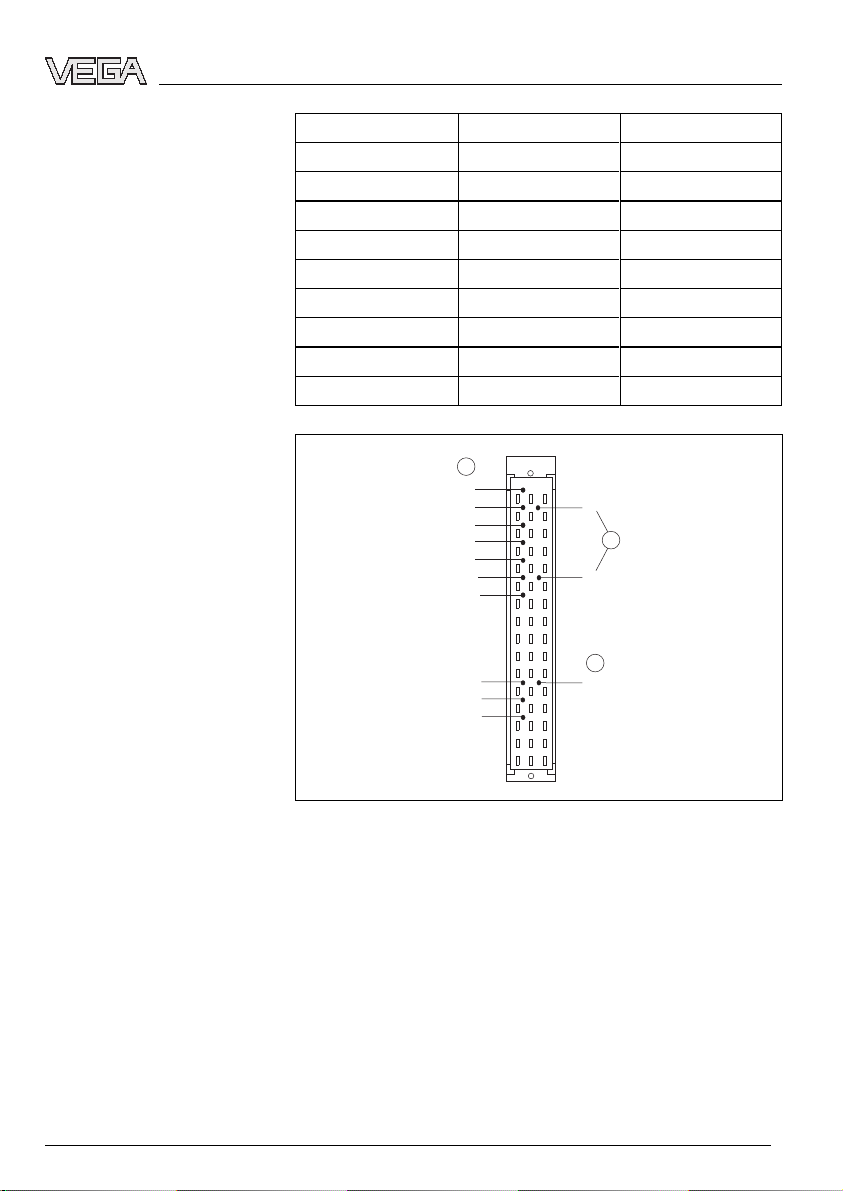
The AT card (output transistor)provides together with the
VEGALOG 571 processing system ten floating outputs via
NPN transistors.
These can be used for transmission of the measuring results,
e.g.to binary input cards of a PLC.
The VEGALOG 571 AT card makes the processing results
available on up to ten outputs.It is suitable for outputting level,
single or sum fault messages.The switching condition of each
output is displayed via a two-coloured LED in the front plate.
Depending on the parameter adjustment,this LED lights
yellow as switching output,or if so configured,red as fault
output.
The voltage supply of the module card is provide via the
common power supply unit of the VEGALOG system.
You can find detailed information on the power supply in the
"Technical data"in the "Supplement".
3.3Operation
The operation of VEGALOG 571 is carried out via a PC which
can be connected via the RS232 interface of the CPU.Asan
alternative,connection via Ethernet and VEGACOM 558 is
possible.
The adjustment software PACTware™with the corresponding
DTMs is installed under Windows™and ensures easy
configuration of measuring systems as well as parameter
adjustment of connected VEGA sensors.For this purpose,
PACTware™provides a clear adjustment interface with menu
structure,window technology and graphic support.In addition,
online help is available which describes the available functions
Scope of delivery
Area of application
Physical principle
Power supply
6VEGALOG 571 AT -Output card transistor
Product description
31951-EN-060720