Nortek R8HE Series User manual

14 SEER / 95% AFUE
SinglE PAckAgE gAS HEAting / ElEctRic cooling
R8HE / PPg3HE SERiES
inStAllAtion inStRUctionS
WARning / AVERtiSSEMEnt
FiRE oR EXPloSion HAZARD
WHAt to Do iF YoU SMEll gAS
RiSQUE D’incEnDiE oU D’ EXPloSion
QUE FAiRE S’il Y A UnE oDEUR DE gAZ
HoRiZontAl MoUnt SHoWn

2
tABlE oF contEntS
iMPoRtAnt SAFEtY inFoRMAtion 3
4
gEnERAl inFoRMAtion 5
Before you install this unit ........................................................... 5
Locating the Equipment .............................................................. 5
Heating Load ............................................................................... 5
5
Vent Termination.......................................................................... 6
ciRcUlAting AiR SUPPlY 7
Air Ducts...................................................................................... 7
Unconditioned Spaces................................................................ 7
Acoustical Duct Work.................................................................. 7
Unit inStAllAtion 7
Packaging Removal..................................................................... 7
Rigging & Hoisting....................................................................... 7
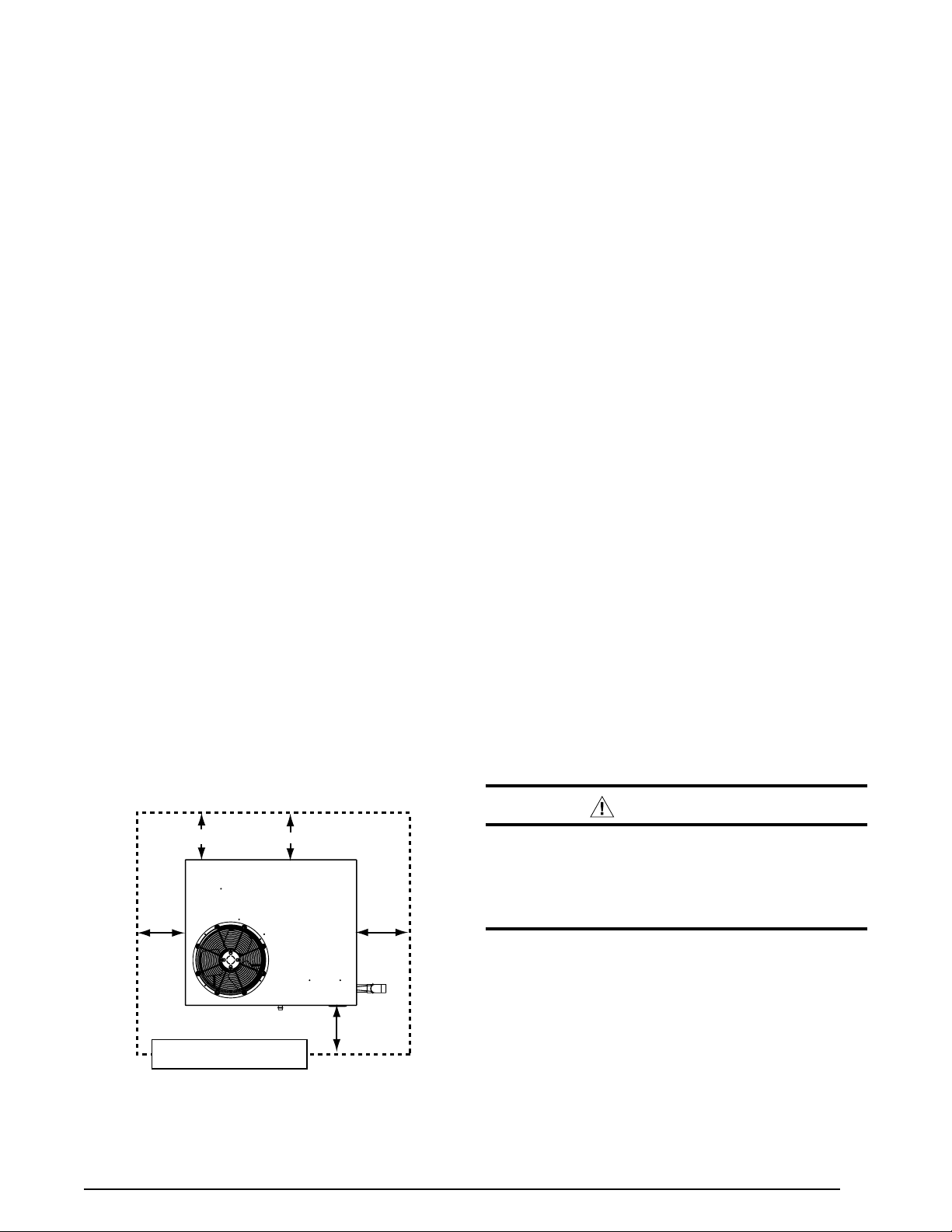
Clearances to Combustible Materials......................................... 8
Ground Level ............................................................................... 8
Rooftop ........................................................................................ 8
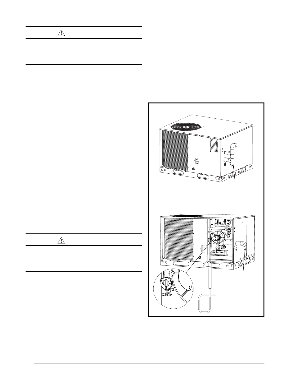
Horizontal to Downflow Conversion............................................ 9
Condensate Drain (Air Conditioning).......................................... 9
Air Filter Requirements................................................................ 9
Removal of Internal Filter Rack................................................... 9
Installing Filters in the Internal Filter Rack.................................. 9
1” to 2” Filter Conversion ......................................................... 9
Removing Filters from Internal Filter Rack.................................. 10
ElEctRicAl WiRing 11
Pre-Electrical Checklist............................................................... 11
Grounding.................................................................................... 11
Line Voltage................................................................................. 11
Unbalanced 3-Phase Supply Voltage......................................... 12
Thermostat / Low Voltage Connections...................................... 12
2-Stage Heat / 1-Stage Cool Thermostat ................................ 12
Single Stage Heat / Single Stage Cool Thermostat................. 12
Heat Anticipator........................................................................... 13
Cooling Configurations................................................................ 13
Heating Configurations................................................................ 13
Blower Speed .............................................................................. 13
Configuring the Fixed Speed Blower ....................................... 13
Selecting Cooling Airflow......................................................... 13
Selecting Heating Airflow......................................................... 13
Dehumidification Options............................................................ 14
Optional Furnace Control Board Connections............................ 14
Electronic Air Cleaner.............................................................. 14
Humidifier ................................................................................ 14
15
Leak Check.................................................................................. 15
High Altitude Conversion - Natural Gas...................................... 16
LP / Propane Gas Conversion..................................................... 16
18
Pre-Start Check List.................................................................... 18
Start-Up Procedure ..................................................................... 18
Air Circulation .......................................................................... 18
Lighting the Appliance............................................................. 18
Verifying System Heating ........................................................ 19
Verifying & Adjusting Temperature Rise .................................. 19
Gas Supply Pressure Verification & Adjustment...................... 19
Verifying the Firing Rate of the Appliance ............................... 19
Measuring the Manifold Pressure............................................ 20
Adjusting the Manifold Pressure.............................................. 20
Removing the Manometer/Pressure Gauge............................ 20
Verifying Over-Temperature Limit Control Operation............... 20
Verifying Burner Operation...................................................... 21
Verifying System Cooling......................................................... 21
oPERAting SEQUEncE 21
Heating Mode .............................................................................. 21
Thaw Cycle Start Up / Shutdown ................................................ 22
Blocked Vent / Condensate Disposal Shut Down....................... 23
Cooling Mode - Single Stage Operation ..................................... 23
De-Humidification Control........................................................... 23
Fan Mode..................................................................................... 23
coMPonEnt FUnctionS 23
EQUiPMEnt MAintEnAncE 24
Heat Exchanger & Burner Maintenance ..................................... 24
Cleaning of Burners..................................................................... 25
REPlAcEMEnt PARtS 25
tRoUBlESHooting 25
Cooling Mode .............................................................................. 25
Heating Mode .............................................................................. 25
26
Figure 8. Unit Dimensions ....................................................... 26
Table 7. Center of Gravity & Shipping Weights........................ 27
28
Table 8. Cooling Airflow Settings ............................................. 28
Table 9. Heating Airflow Settings............................................. 28
Table 10. Blower Performance - 2 & 2.5 Ton............................ 29
Table 11. Blower Performance - 3 Ton ..................................... 30
Table 12. Blower Performance - 3.5 Ton .................................. 31
Table 13. Blower Performance - 4 & 5 Ton............................... 32
33
Table 14. Gas Pipe Capacities................................................. 33
Table 15. Gas Flow Rates........................................................ 33
Figure 9. Gas Valve Label........................................................ 34
35
Table 16. Electrical Data.......................................................... 35
Table 17. Copper Wire Size ..................................................... 35
Table 18. Thermostat Wire Gauge........................................... 35
36
Figure 10. Two Stage Heating / Single Stage Cooling
Configuration........................................................... 36
Figure 11. Fixed Speed Motor Control Board .......................... 36
Figure 12. Ignition Control Board - 624817 ............................. 36
37
Figure 13. Single Phase, 2-5 Ton, 208/230V .......................... 37
Figure 14. Three Phase, 3-5 Ton, 208/230V............................ 38
Figure 15. Three Phase, 3-5 Ton, 460V................................... 39
40
Figure 16. Charging Chart for 2 Ton Units ............................... 40
Figure 17. Charging Chart for 2.5 Ton Units ............................ 40
Figure 18. Charging Chart for 3 Ton Units ............................... 41
Figure 19. Charging Chart for 3.5 Ton Units ............................ 41
Figure 20. Charging Chart for 4 Ton Units ............................... 42
Figure 21. Charging Chart for 5 Ton Units ............................... 42
43
Figure 22. Filter Comversion ................................................... 43
44
About the Kit................................................................................ 44
Vent Pipe & Drain Hose Assembly.............................................. 44
Vertical Drain Pit Method ............................................................ 44
Preparing the pit...................................................................... 45
Percolation Test (Optional) ...................................................... 45
Vertical Drain Pipe Installation................................................. 45
Horizontal Drain Trench Method ................................................. 45
Preparing the Trench ............................................................... 46
Horizontal Drain Pipe Installation ............................................ 46
Completing the Vent Installation ................................................. 46
48
About the Kit................................................................................ 48
Before Setting unit on the Curb................................................... 48
Setting the Unit............................................................................ 49
Completing the Heat Exchanger Condensate Drain Installation 49
Completing the Vent Pipe Installation and Assembly................. 49
inStAllAtion / PERFoRMAncE cHEck liSt 52

3
iMPoRtAnt SAFEtY inFoRMAtion
Pleaseread allinstructions beforeservicing thisequipment.
Pay attention to all safety warnings and any other special
notes highlighted in the manual. Safety markings are
used frequently throughout this manual to designate a
degree or level of seriousness and should not be ignored.
WARningindicatesa potentially hazardous situation that
if not avoided, could result in personal injury or death.
cAUtion indicates a potentially hazardous situation that
if not avoided, may result in minor or moderate injury or
property damage.
WARning:
EXPloSion HAZARD
WARning:
WARning:
WARning:
WARning:
• Before beginning the installation, verify that the unit
model is correct for the job. The unit model number
is printed on the data label. Follow all precautions in
the literature, on tags, and on labels provided with
the equipment. Read and thoroughly understand
the instructions provided with the equipment prior to
performing the installation and operational checkout
of the equipment.
• Never test for gas leaks with an open ame. Use
a commercially available soap solution to check all
connections. See page 15.
• Installationofequipmentmayrequirebrazingoperations.
Installer must comply with safety codes and wear
appropriate safety equipment (safety glasses, work
gloves, fire extinguisher, etc.) when performing brazing
operations.
• Thisequipmentisnot to be used for temporary heating
of buildings or structures under construction.
• Usecautionwhenhandlingthisapplianceorremoving
components.Personal injury canoccurfrom sharpmetal
edgespresentin all sheet metal constructedequipment.
• Follow all precautions in the literature, on tags, and
on labels provided with the equipment. Read and
thoroughly understand the instructions provided with
the equipment prior to performing the installation and
operational checkout of the equipment.

4
• Theinstallershouldbecomefamiliarwiththeunitswiring
diagrambeforemakingany electrical connections to the
unit. See the unit wiring label or Figure 13 (page 37),
Figure 14 (page 38), & Figure 15 (page 39).
•
• Allelectricalwiringmustbecompletedinaccordance
with local, state and national codes and regulations
and with the National Electric Code (ANSI/NFPA 70)
or in Canada the Canadian Electric Code Part 1 CSA
C.22.1.
• The installer must comply with all local codes and
regulations which govern the installation of this type
of equipment. Local codes and regulations take
precedence over any recommendations contained in
these instructions. Consult local building codes and the
NationalElectrical Code (ANSICI)for specialinstallation
requirements.
• Thisequipmentcontainsliquidandgaseousrefrigerant
underhighpressure. Installation orservicingshould only
be performed by qualified trained personnel thoroughly
familiar with this type equipment.
• Installthisunitonlyinalocationandpositionasspecied
on page 5. This unit is designed only for outdoor
installations and should be located with consideration
of minimizing the length of the supply and return ducts.
Consideration should also be given to the accessibility
of fuel, electric power, service access, noise, shade,
and drainage for the units heat exchanger condensate
drainage pit.
• Air Ducts must be installed in accordance with the
standards of the National Fire Protection Association
“Standards for Installation of Air Conditioning and
Ventilation Systems” (NFPA 90A), “Standard for
InstallationofResidence Type Warm AirHeatingand Air
Conditioning Systems” (NFPA 90B), these instructions,
and all applicable local codes. See page 7for
additional information.
• Consult Table 8 (page 28), Table 9 (page 28),
Table 10 (page 29), Table 11 (page 30), Table
12 (page 31) & Table 13 (page 32), and the rating
plate for the proper circulating air flow and temperature
rise. It is important that the duct system be designed
to provide the correct flow rates and external pressure
rise. An improperly designed duct system can result in
nuisance shutdowns, and comfort or noise issues.
• Useonlywiththe typeofgasapprovedforthis unit.
Refer to the unit rating plate.
• Provideadequatecombustionandventilationairtothe
unit. See page 5, page 6, & page 7.
• Provideadequateclearancesaroundthecombustion
air intake louvers. See Figure 1 (page 5).
• Combustion products must be discharged outdoors.
Connect this unit to an approved vent system only, as
specified on page 6 and in the Appendix (pages 36-38).
• Theinformationlistedbelowisforreferencepurposes
only and does not necessarily have jurisdiction over
localorstate codes. Always consultwithlocal authorities
before installing any gas appliance.
• US:NationalFuelGasCode(NFGC),AirforCombustion
and Ventilation
• CANADA:NaturalGasandPropaneInstallationCodes
(NSCNGPIC), Venting Systems and Air Supply for
Appliances
• US and CANADA: Air Conditioning Contractors
Association (ACCA) Manual D, Sheet Metal and
Air Conditioning Contractors National Association
(SMACNA), or American Society of Heating,
Refrigeration,andAirConditioningEngineers(ASHRAE)
Fundamentals Handbook
• US:NationalElectricalCode(NEC)ANSI/NFPA70
• CANADA:CanadianElectricalCodeCSAC22.1
• US:NFGCandNationalPlumbingCodes
• CANADA:NSCNGPIC
• US:CurrenteditionoftheNFGCandtheNFPA90B.For
copies, contact the National Fire Protection Association
Inc.,BatterymarchPark,Quincy,MA 02269;orAmerican
Gas Association, 400 N. Capitol, N.W., Washington DC
20001 or www.NFPA.org
• CANADA:NSCNGPIC.Foracopy,contactStandard
Sales, CSA International, 178 Rexdale Boulevard,
Etobicoke (Toronto), Ontario, M9W 1R3 Canada
• US: (NFGC) NFPA 54–1999/ANSI Z223.1 and the
Installation Standards, Warm Air Heating and Air
Conditioning Systems ANSI/NFPA 90B.
• CANADA: CAN/CGA-B149.1 and .2–M00 National
Standard of Canada. (NSCNGPIC)

5
gEnERAl inFoRMAtion
This Single Package Gas Heating / Electric Cooling
Unit is designed for outdoor rooftop or ground level
slab installations and can be readily connected to the
duct system of a home or building. This unit has been
tested for capacity and efficiency in accordance with
AHRI standards and will provide many years of safe and
dependable comfort, providing it is properly installed
and maintained. With regular maintenance, this unit will
operate satisfactorily year after year. Abuse, improper
use, and/or improper maintenance can shorten the life
of the appliance and create unsafe hazards.
Toachieveoptimumperformanceandminimizeequipment
failure, it is recommended that periodic maintenance be
performed on this unit. The ability to properly perform
maintenance on this equipment requires certain tools
and mechanical skills.
√The cooling load of the area to be conditioned must be
calculatedandasystem of the proper capacity selected.
It is recommended that the area to be conditioned be
completely insulated and vapor sealed.
√Check the electrical supply and verify the power supply
is adequate for unit operation. Consideration should be
given to availability of electric power, service access,
noise, and shade. If there is any question concerning
the power supply, contact the local power company.
√All units are securely packed at the time of shipment and
upon arrival should be carefully inspected for damage
prior to installing the equipment at the job site. Verify
coil fins are straight. If necessary, comb fins to remove
flattened or bent fins. Claims for damage (apparent or
concealed) should be filed immediately with the carrier.
√Survey the job site to determine the best location for
setting the unit. Choose an appropriate location that
minimizes the length of the supply and return air ducts.
√Please consult your dealer for maintenance information
and availability of maintenance contracts. Please read
all instructions before installing the unit.
• Selectasolid,levelposition,preferablyonaconcrete
slab, slightly above the grade level, and parallel to the
home.
• Overhead obstructions, poorly ventilated areas, and
areas subject to accumulation of debris should be
avoided. Do not place the unit in a confined space or
recessed area where discharge air from the unit to re-
circulate into the condenser air inlet, through the coil.
• Sufcientclearanceforunobstructedairowthroughthe
louvered control access panel and outdoor coil must
be maintained in order to achieve rated performance.
See Figure 1 for minimum clearances to obstructions.
• A clearance of at least 36 inches from the blower
access panel and from the louvered control access
panel is recommended for servicing and maintenance.
• Thehotcondenserairmustbedischargedupandaway
from the home, and if possible, in a direction with the
prevailing wind.
• Ifpractical,placetheairconditioneranditsductsinan
area where they will be shaded from the afternoon sun,
when the heat load is greatest.
This unit should be sized to provide the design heating
load requirement. Heating load estimates can be made
using approved methods available from Air Conditioning
Contractors of America (Manual J); American Society of
Heating, Refrigerating, and Air Conditioning Engineers;
or other approved engineering methods. For installations
above 2,000 ft., the unit should have a sea level input
rating large enough that it will meet the heating load after
deration for altitude.
REQUiREMEntS
WARning:
• Provisions must be made during the installation of
this unit that provide an adequate supply of air for
combustion.
• Instructions for determining the adequacy of an
installation can be found in the current revision of the
NFGC(ANSIZ223.1/NFPA54).
. These requirements are for
US installations as found in the NFGC.
• TherequirementsinCanada(B149.1)arestructured
differently. Consult with B149.1 and local code officials
for Canadian installations.
Minimum Required
Clearances to Combustibles
36"
36"
36"
See Note 1 See Note 2
NOTE 1: 6” When coil is present on duct side.
NOTE 2: 1” When no coil is present on duct side.

6
WARning:
To maximize heat exchanger life, the combustion air
must be free of chemicals which form corrosive acidic
compounds in the combustion gases.
iMPoRtAnt notE:
• CarbontetraChloride • Gasoline/Kerosene
• Cements,Glues,paintremovers,
varnishes,etC.• haloGentyperefriGerants
• CleaninGsolvents • hydroChloriCaCid
• ChlorinebasedswimminGpool
ChemiCals • masonryaCidwashinGmaterials
• Chlorinatedwaxes&Cleaners • permanentwavesolutions
• de-iCinGsaltsorChemiCals • watersofteninGChemiCals
This unit has been developed for use with a combination
heat exchanger condensate drain and venting system
designed to operate only with this type of system.
CondensateDrain and VentKitsareavailable forpurchase
as accessory items.
Horizontalground mountapplicationscan use P/N-922323
to attach the 13.25” x 2” PVC pipe within the control area of
thisunit.Rooftop mount applicationscanuse the downflow
condensate drain / vent kit (P/N-922485).
If Nordyne kits are not being used, see Appendix on page
44 or page 46 for your specific application.
WARning:
Figure 2 shows the
proper installation of the vent and drain assembly for both
horizontal and downflow applications. The fasteners used
tosecurethe vent and drain assembly have been included
in the kit. The following list summarizes the requirements
forthelocationoftheventsystemtermination:
• Thelocationoftheventterminationmustbeconsistent
withtheNationalFuelGasCode(ANSIZ223.1)orCAN/
CGA-B149 Installation Codes.
• Theventterminationmustbelocatedatleast4feet
horizontally from any electric meters, gas meters,
regulators, and relief equipment.
HORIZONTAL GROUND MOUNT
Combined condensate
Drain / Vent System
ROOF MOUNTED UNIT
(ROOF CURB AND ROOF NOT SHOWN)
2” PVC x 22.5 Degree Elbow
& 1/4” Mesh Screen
• Theventterminationmustbelocatedatleast3feet
above any forced air inlet located within 10 feet.
• Theventterminationmustbelocatedatleast4feet
below, 4 feet horizontally from, or 1 foot above any
door, window, or gravity air inlet into any building.
• Theunitshouldbeinstalledinawaythatpreventsany
obstruction of the vent termination during accumulating
snow.
• Verify exhaust gases will not impinge on windows
or building surfaces, which may be compromised or
damaged by condensation.
• Donotinstalltheunitsuchthatexhaustfromthevent
termination is directed into window wells, stairwells,
under decks, or in alcoves or similarly recessed areas.

7
ciRcUlAting AiR SUPPlY
WARning:
This unit is designed only for use with a supply and return
duct. Air ducts should be installed in accordance with the
standards of the National Fire Protection Association
“Standard for Installation of Air Conditioning Systems”
(NFPA 90A), “Standard for Installation of Residence Type
Warm Air Heating and Air Conditioning Systems” (NFPA
90B), and all applicable local codes. NFPA publications
are available by writing to: National Fire Protection
Association, Batterymarch Park, Quincy, ME 02269 or
visit www.NFPA.org on the web.
• DesigntheductworkaccordingtoManualDbytheAir
Conditioning Contractors of America (ACCA).
• Theductsmust be properly sizednottoexceed the
units maximum ESP rating at 400 SCFM per nominal
ton of cooling capacity.
• Ductworkshouldbeattacheddirectlytotheunitanges
for horizontal applications.
• Ifaroofcurbisinstalled,theductsmustbeattachedto
the curb hangers, not the unit.
• It is recommended that the outlet duct be provided
with a removable access panel. The opening should
be accessible when the unit is installed in service and
shall be sizes so that smoke or reflected light may be
observed inside the casing to indicate the presence of
leaks in the heat exchanger. The cover for the opening
shall be attached in a way that will prevent leaks.
• If outside air is utilized as return air to the unit for
ventilation or to improve indoor air quality, the system
must be designed so that the return air to the unit is not
less than 50° F (10° C) during heating operation.
• Ifacombinationofindoorandoutdoorairisused,the
ducts and damper system must be designed so that the
return air supply to the furnace is equal to the return air
supply under normal, indoor return air applications.
All duct work passing through unconditioned space must
be properly insulated to minimize duct losses and prevent
condensation. Use insulation with an outer vapor barrier.
Refer to local codes for insulation material requirements.
Certain installations may require the use of acoustical
lining inside the supply duct work.
• Acousticalinsulationmustbeinaccordancewiththe
current revision of the Sheet Metal and Air Conditioning
ContractorsNational Association(SMACNA)application
standard for duct liners.
• DuctliningmustbeULclassiedbattsorblanketswith
a fire hazard classification of FHC-25/50 or less.
• Fiberductworkmaybeusedinplaceofinternalduct
liners if the fiber duct work is in accordance with the
current revision of the SMACNA construction standard
on fibrous glass ducts. Fibrous duct work and internal
acoustical lining must be NFPA Class 1 air ducts when
tested per UL Standard 181 for Class 1 ducts.
Unit inStAllAtion
Remove the shipping carton and User’s Manual from the
equipment. Set aside the 13” x 2” PVC pipe for later use
when installing the heat exchanger condensate drain and
vent kit. Take care not to damage the coil or cabinet when
removing the carton. For rooftop installations, remove
and discard the two supports attached beneath the unit
WARning:
27
20
49

8
These units are certified as combination heating and
cooling equipment for outdoor rooftop or ground level
installations. Units may be installed on combustible
flooring or class A, B, or C roofing material when used
with bottom supply and return air ducts as long as the
followingrequirementsaremet:
• Ifusingbottomdischargewithreturnairductsaroof
curb must be installed prior to unit installation. See
Rigging and Hoisting section for setting of the unit.
• Sufcientclearanceforunobstructedairowthroughthe
outdoor coil must also be maintained in order to achieve
rated performance. For information about locating the
equipment, see page 5.
2”
ROOFTOP INSTALLATION
GROUND LEVEL INSTALLATION
ACCESSORY
ROOF CURB
Ground level installations must be located according to
localbuildingcodesorordinancesandtheserequirements:
• Clearancesmustbeinaccordancewiththoseshown
in Figure 1 (page 5).
• A suitable mounting pad must be provided and be
separate from the building foundation. The pad must be
level to ensure proper condensate disposal and strong
enough to support the unit’s weight. The slab height
must be a minimum of 2” (5cm) above grade and with
adequate drainage. See Figure 3.
• RemoveanddiscardthehorizontalSupplyandReturn
duct covers located on the rear of the unit. Form duct
attachment flanges by bending the sheet metal outward
90 degrees along the perforated lines.
• Firmly attach ductwork directly to these anges with
screws or other approved mechanical connections and
not to the Supply/Return air panels to avoid damage to
internal components of the equipment. Use approved
duct sealing methods to ensure an air and watertight
seal is achieved.
Rooftop installations must be located according to local
buildingcodesorordinancesandtheserequirements:
• Theroofmustbecapableofhandlingtheweightofthe
unit. Reinforce the roof if necessary For unit weights,
see Table 7 (page 27).
• Theappropriateaccessoryroofcurbmustbeinstalled
prior to unit installation. The roof curb must be square
and level to ensure proper condensate drainage. See
Figure 2 (page 6).
• Secure roof curb or frame to roof using acceptable
mechanicalmethodsper local codes. notE: Make sure
the two supports beneath the unit have been removed.
iMPoRtAnt notES to inStAllER
• Whensettingtheroofcurbforinstallation,routingand
securement of the gas heat exchanger condensate
drain line must be determined and installed prior to
setting the unit on the curb. It is recommended to drill
a 1.00”-1.25” diameter hole through the roof below
the rectangular opening located in outer close off curb
panel (G) of Nordyne offered curbs, approximately 15”
in from the short side of curb and 1”-2” in from the long
side of curb. If drilling a hole is not an option, routing the
condensatedrain hose overtothe ductpassageopening
with enough slope is acceptable as long as drain line is
secured to curb and duct, ensuring no kinks or traps can
form between the collector box drain or interior of the
building. Leave a minimum of 24” drain line extending
out the top of roof curb front close off panel (G) for
passage through unit bottom and connection to unit
drain when unit is being set. See unit or Condensate/
Vent Drain Kit (P/N-922485) instructions for completion
of the drain connection.
• Itisrecommendednonon-serviceableconnectionsare
introducedin thedrainline betweenunitdrain connection
and an accessible area within the building interior.

9
• Securementofthedrainlinetotheinsidesurfaceof
the roof curb is acceptable and should be made in the
wood nailer area (top 3.5”) to avoid possible leaks or
penetrations to roofing materials.
• Cut and remove the insulation covering the 2” x 3”
condensatedrain passageinouterpanel(G) only.Before
installing inner panel (G) ensure there is enough slope
and there are no kinks or high spots that could trap
water in the line prior to entering the warmer interior of
the building where a drain trap is acceptable.
• All panels must be securely in place during rigging and
hoisting, except control access panel. See page 49
for additional lifting and setting of unit requirements.
The unit is shipped ready for horizontal duct connections.
Ifdownflow ducts are required, the unit must be converted
following the steps below for both the supply and return
ducts.
1.Remove both horizontal duct caps.
2. Locate theduct cap insidethe ductopenings andremove
the screw holding it in place.
3. Lift the cap out of the unit.(The cap can be pushed
up from the bottom by reaching through the fork slot).
4.Cover the horizontal duct openings with the horizontal
duct caps removed earlier in step 1. The insulation will
be on the indoor side.
5.Fasten the cover with screws to seal.
6.Remove and discard the two wood supports beneath
the unit.
Air conditioning condensate is removed from the unit
through the 3/4” female pipe and supplied fitting located
on the front side of the unit. Figure 4 (page 10).
Install a 2 inch condensate trap in the drain line of the
same size and prime with water. When connecting rigid
drain line, hold the female fitting with a wrench to prevent
twisting. Refer to local codes and
restrictions for proper condensate disposal requirements.
WARning:
notE to inStAllER: After installing or replacing the
filtration system for this unit, add the following statement
on or adjacent to the lter service panel:
• Asuitableairltermustbeinstalledupstreamofthe
evaporatorcoilofthereturnairsystem.Forrecommended
external filter sizes, refer to Table 1 (page 10).
• Allreturnairmustpassthroughtheltersbeforeentering
the evaporator coil. It is important that all filters be kept
cleanand replacedfrequentlyto ensureproperoperation
of unit. Dirty or clogged filters will reduce the efficiency
of the unit and result in unit shutdowns.
• Airlterpressuredropisrecommendednottoexceed
0.08 inches WC.
• Single phase downow applications require either a
Nordyne internal filter kit be used or an air filter system
be installed in the return air ductwork. Three phase
models are factory equipped with an internal filter
rack ready to accept 1 inch filters (field supplied). See
Table 1 for specific unit model and filter sizes. Nordyne
internal filter rack adjusts for 1” or 2” filters. To convert
the unit from 1 inch to 2 inch filters, see 1” to 2” Filter
Conversion section below.
• Horizontalinstallationsrequiretheairltersystembe
installed in the return air ductwork.
(If Equipped, only required if economizer is
installed)
1.Remove the return air panel from the unit.
2.Remove the height adjustment screw from the inside
of the rack.
3.Remove 4 screws securing the assembly to the coil
located on the left leg of the rack. notE: The assembly
can now be easily collapsed and removed from the
unit.The bracket secured to the top rear of the coil can
remain in place. See Figure 5 (page 10)for filter rack
securing screw locations.
(If Equipped)
1.Remove access panel screws from return air panel.
( Loosen the unit’s top panel screws near the
top edge of the access panel. The access panel was
designed to be captured underneath the top panel.)
2.Slide the first filter between both guide channels of filter
rack and allow the filter to drop easily into place.
3.Verify the bottom of the filter is within the channels of
the rack.
4.Slide the 2nd filter (and 3rd filter on taller models)
between both guide channels of filter rack.
5.Verify the top of the filter is within the channels of the
rack.
6.Replace access cover by sliding the top edge of panel
under the lip of the unit’s top panel. Secure access
panel by replacing the screws.
1” to 2” Filter Conversion
Factory installed internal filter rack (3 phase models only)
is set up to accept 1” filters. If conversion to 2” filters is
desired,remove thetwo(or three)1”filter adaptorssecured
in the assembly with clips by pulling straight off the frame.
The filter bracket must be reoriented to accept 2” filters by
removing two screws securing it to the hinge and rotating
180 degrees. See Figure 22 (page 43).

10
HIGH SIDE
LOW SIDE
CONDENSATE
DRAIN
Securing
Screws
EXtERnAl FiltER SiZES
noMinAl
cooling
FiltER SiZE
APPRoXiMAtE
AiR FloW
APPRoXiMAtE
FiltER AREA
2.0 20 x 25 600-900 450
2.5 20 x 30 750-1200 550
3.0 25 x 25 1100-1300 625
3.5 24 x 30 1200-1600 750
4.0 18 x 24 (2 required) 1400-1800 850
5.0 20 x 25 (2 required) 1700-2200 1000
intERnAl FiltER SiZES
cABinEt
HEigHt
oUtDooR
FAn
DiAMEtER
FiltER SiZE
APPRoXiMAtE
AiR FloW
APPRoXiMAtE
FiltER AREA
30” 20 (2) 14”x25” 700 - 1300 700
24” (1) 12”x20” and (1) 16”x25” 640
34” 20 (2) 16”x25” 900 - 1400 800
24” (1) 12”x20” and (2) 10”x25” 740
38” 20” (2) 18”x25” 1100 - 1600 900
24” (1) 12”x20” and (2) 12”x25” 840
42” 20” (2) 20”x25” 1300 - 1800 1000
24” (1) 12”x20” and (2) 14”x25” 940
* Based on velocity of 300 ft/min for disposable filters.
(If Equipped)
1.Remove access panel screws from return air panel.
( Loosen the unit’s top panel screws near the
top edge of the access panel. The access panel was
designed to be captured underneath the top panel.)
2.Remove upper filter by gently pulling filter through the
access panel opening.
3.Remove lower filter by lifting media to top of filter rack.
Remove in the same manner as described in step 2.
4.Install new filter in the filter rack as described in the
previous section.

11
ElEctRicAl WiRing
WARning:
EXPloSion HAZARD
AVERtiSSEMEnt:
D’incEnDiE oU D’EXPloSion
• Electricalconnectionsmustbeincompliancewithall
applicable local codes with the current revision of the
National Electric Code (ANSI/NFPA 70).
• For Canadian installations the electrical connections
and grounding shall comply with the current Canadian
Electrical Code (CSA C22.1 and/or local codes).
iMPoRtAnt notE:
(Single & 3-Phase Models)
√Verify the voltage, frequency, and phase of the supply
source match the specifications on the unit rating plate.
√Verify that the service provided by the utility is sufficient
tohandle the additionalload imposedbythis equipment.
See Table 16 (page 35) (or the unit rating label) for
proper high voltage wiring requirements.
√Verify factory wiring is in accordance with the unit wiring
diagram. Figure 13 (page 37), Figure 14 (page 38),
& Figure 15 (page 39). Make sure the connections
didn’t loosen during shipping or installation.
√
12
WARning:
This unit must be electrically grounded in accordance with
local codes or, in the absence of local codes, with the
NationalElectricalCode(ANSI/NFPA 70)or theCSA C22.1
Electrical Code. Grounding of the unit is accomplished
by using the grounding lug provided in the control box.
• Thelinevoltagetotheunitshouldbesuppliedfroma
dedicated branch circuit containing the correct fuse or
circuit breaker for the unit.
•
. This switch shall
becapableof electrically de-energizing the outdoorunit.
See unit data label for proper incoming field wiring. Any
other wiring methods must be acceptable to authority
having jurisdiction.
• Useonlycopperwireforthelinevoltagepowersupply
to this unit. See Table 17 (page 35). Use proper
code agency listed conduit and a conduit connector
for connecting the supply wires to the unit. Use of rain
tight conduit is recommended.
• Providepowersupplyfortheunitinaccordancewith
the unit wiring diagram and the unit rating plate.
• Overcurrentprotectionmustbeprovidedatthebranch
circuit distribution panel and sized as shown on the unit
rating label and according to applicable local codes.
See Table 16 (page 35) or the unit rating plate for
minimum circuit ampacity and maximum overcurrent
protection limits.
• Awiringdiagramislocatedontheinsidecoverofthe
control access panel of the outdoor unit. The installer
should become familiar with the wiring diagram before
making any electrical connections to the outdoor unit.
See Figure 13 (page 37), Figure 14 (page 38), &
Figure 15 (page 39).

12
• All208-240voltunitsareshippedfromthefactorywired
for 240 volt transformer operation. For 208V operation,
remove the lead from the transformer terminal marked
240V and connect it to the terminal marked 208V.
• Connecttheline-voltageleadstotheterminalsonthe
contactor inside the control compartment.
Voltageunbalanceoccurs when the voltages ofallphases
of a 3-phase power supply are no longer equal. This
unbalance reduces motor efficiency and performance.
Some underlying causes of voltage unbalance may
include:Lack of symmetryin transmission lines,large
single-phase loads, and unbalanced or overloaded
transformers. A motor should never be operated when a
phase imbalance in supply is greater than 2%.
Perform the following steps to determine the percentage
ofvoltageimbalance:
1. Measurethelinevoltages
of your 3-phase power
supply where it enters
the building and at a
location that will only
be dedicated to the
unit installation. (at the
units circuit protection or
disconnect).
EXAMPlE:
AB = 451V
BC = 460V
AC = 453V
2.Determine the average voltage in the power supply.
In this example, the measured line voltages were 451,
460, and 453. The average would be 454 volts (451 +
460 + 453 = 1,364 / 3 = 454).
3.Determinethemaximumdeviation:
EXAMPlE
From the values given in step 1, the BC voltage (460V)
isthegreatestdifferenceinvaluefromtheaverage:
460 - 454 = 6
454 - 451 = 3
454 - 453 = 1
4.Determine percent of
voltage imbalance by
using the results from
steps2&3inthefollowing
equation.
6
454
100 x = 1.32%
EXAMPlE
maxvoltage deviation
fromaverage voltage
=100 x averagevoltage
% Voltage Imbalance
The amount of phase imbalance (1.32%) is satisfactory
since the amount is lower than the maximum allowable
2%. Please contact your local electric utility company if
your voltage imbalance is more than 2%.
Highest Value
• Thisunitisdesignedtooperatefroma24VACClassII
control circuit. A single stage cooling / two stage heating
thermostat should be used with this unit. See Figure 10
(page 36)for typical thermostat connection.
• Thecontrolcircuitwiringmustcomplywiththecurrent
provisions of the NEC (ANSI/NFPA 70) and with
applicable local codes having jurisdiction. Thermostat
connections should be made in accordance with the
instructions supplied with the thermostat and the indoor
equipment.
• The low voltage wires must be properly connected.
Route 24V control wires through the sealing grommet
near the power entrance. Recommended wire gauge
and wire lengths for typical thermostat connections are
listed in Table 18 (page 35).
• Several thermostat options are available depending
on the accessories installed with the unit. Select a
thermostatthatoperates in conjunction withtheinstalled
accessories.
• Thethermostatshouldbemountedabout5feetabove
thefloor on aninsidewall. DO NOTinstallthe thermostat
on an outside wall or any other location where its
operationmay beadverselyaffected byradiantheat from
fireplaces, sunlight, or lighting fixtures, and convective
heat from warm air registers or electrical appliances.
Refertothe thermostat manufacturer’s instruction sheet
for detailed mounting information.
2-Stage Heat / 1-Stage Cool Thermostat
(Recommended): Forhighest efficiencya2 Stage Heating/
Single Cooling thermostat is recommended for this unit. A
Single Stage Cool thermostat is only required for cooling
operation control of this unit. A 2 Stage Heat thermostat
will allow the gas heat to operate at a more efficient low
heat condition until there is a demand for higher heat
output to the conditioned space.
Single Stage Heat / Single Stage Cool
Thermostat
(Optional):ASingleStageCoolthermostatisonlyrequired
for cooling operation of this unit. A Single Stage Heat
thermostat can be used in conjunction with the automatic
heatstagingjumperon the ignition control board. The heat
staging function will automatically move the unit into high
heat operation after 10 minutes when the jumper is moved
from OFF to the ON position. See Figure 12 (page 36).
Connect the Red, Yellow, Green, White, and Brown low
voltage thermostat wires to terminals R, Y1 (1st Stage
Cool), g, W1 (1st Stage Heat), & W2 2nd Stage Heat-
optional) on both the thermostat sub-base and unit low
voltage terminal board. The cterminal (Black wire), is the
24V common wire required on some thermostat models.
See Figure 10 (page 36).

13
Verify if the thermostat being used for the installation
has a heat anticipator setting. This function allows the
thermostat to anticipate the space heating rate and time
the burner to shutoff accordingly. Always refer to the
thermostatmanufacturer’s instructions forcorrectsettings.
• Addthecurrentdrawofthesystemheatingcomponents.
OR
• MeasurethecurrentowonthethermostatR-Wcircuit
afterthe circulatingblower motorhasstarted.Setthe heat
anticipator according to the thermostat manufacturer’s
instructions for heat anticipator settings.
This unit is designed to connect with any single stage
cooling thermostat. The connection between Y1 on the
thermostat and Y1 on the unit terminal strip energizes
cooling operation. See Figure 10 (page 36).
This gas pack is factory configured for two stage gas
heating operation with a two stage heating thermostat.
Connect the low voltage thermostat White & Brown wires
to W1 & W2, between the unit low voltage terminal board
and thermostat sub-base. See Figure 10.
To operate with a single stage heat thermostat, only
connect the low voltage thermostat White wire between
W1 on the unit low voltage terminal board and thermostat
sub-base. Reposition the automatic heat staging jumper
located on the ignition control module from OFF to ON
to set a 10 minute time delay before the gas furnace will
automatically move to high heat operation. notE: When
lowfireon the gas valve is energized,thefurnaceoperates
in low fire mode at a lower blower speed and the timer
begins its delay function. If the room thermostat is not
satisfied before the timer activates, the furnace will stage
to high fire. The inducer motor and blower will ramp to a
higher speed until the thermostat is satisfied.
The blower speed is preset at the factory for proper
fan only, heating, and cooling operation. These factory
settings are listed in Table 8 (page 28), Table 9 (page
28), Table 10 (page 29), Table 11 (page 30), Table
12 (page 31)& Table 13 (page 32). For optimum
system performance and comfort, it may be necessary to
change the factory set speed.
notES:
• TheCFMvalueslistedinTable 8, Table 9, Table 10,
Table 11, Table 12 & Table 13 are DEPENDANT on
duct static pressure for individual switch settings.
• Ifcoilicingoccurs,thebasiccoolingairowselected
may be too low. Verify the selected setting is within
the range shown in Table 8 and the system is properly
charged. If icing continues, raise the selected airflow
to the next higher tap.
• Formaximumdehumidicationandenergyefciency,
select an airflow near the middle or bottom of the CFM
range for that nominal capacity.
• The 2-stage heating feature of the unit requires
modulating the airflow. The unit will automatically adjust
the airflow to the appropriate rate when the unit heating
capacity changes.
Configuring the Fixed Speed Blower
The fixed speed blower assembly has been designed to
givetheinstallermaximumflexibilityforoptimizingsystem
performance, efficiency, and comfort. It is equipped with
a microprocessor-controlled motor when coupled with a
fixed speed motor control board delivers constant torque
to optimize airflow in a variety of conditions and system
configurations. Because the blower can be configured in
manyways,it is importanttoread and follow allinstructions
carefully.
Upon initial start up, the fixed speed blower must be
checked so that the factory settings match the unit with
the system, climatic conditions, and other system options.
With the blower installed and configured properly, the
furnace will change speed in response to changes in
system variables such as Heat/Cool setting, Fan Auto/
On, or 2 Stage furnace High/Low Heat. The fixed speed
blower is configured by setting the 8 switches for heating
andcoolingoperationlocated on the blower control board.
Use pins 1 to 4 to set the blower speed for heating and
pins 5 to 8 to set the speed for cooling. To determine the
appropriate switch settings for your installation, see Table
9, Table 10, Table 11, Table 12 & Table 13 for heating or
Table 8 for cooling. See Figure 10 (page 36)for switch
locations. notE: For change in blower speed selection to
takeeffect,systempowermustbecycledoffthenrestored
after 10 seconds.
Selecting Cooling Airflow
(Switches # 5, 6, 7, & 8)
The COOLING airflow is selected by setting switches # 5,
6, 7, & 8 on the motor control board (Figure 10). Table 8
(page 28) lists the recommended airflow values (CFM)
and switch settings for each nominal cooling system
capacity. All airflows for other modes of operation are
determinedbythesebasic settings.For maximumcapacity,
generally, a selection near the middle or top of the CFM
range for that nominal capacity is used. Factory settings
are displayed in BOLD ITALICS
Selecting Heating Airflow
(Switches # 1, 2, 3, & 4)
The HEATING airflow is selected by setting switches #
1, 2, 3, & 4 on the motor control board (Figure 10, Page
31). Table 9, Table 10, Table 11, Table 12 & Table 13
list the recommended airflow values (CFM) and switch
settings for each heat exchanger capacity. All airflows are
determined by these basic settings. For most applications
thefactoryheatsetting will operate at a nominal rise based
on the furnace’s nominal efficiency and firing input. Follow
across the table row to find the switch setting and nominal

14
air-flow. Verify the selected rise is within the specification
shown on the furnace rating label or in the tables.
The fixed speed motor control board has a DEHUM
connection that allows the system to increase the amount
of humidity that is removed from the circulating air. This
is accomplished by reducing the CFM and allowing the
coolingcoil tobecome colder. Thisfunctionisonlyavailable
when there is a call for cooling. There are many ways this
function can be electrically wired.
When 24VAC is present at the DEHUM terminal of the
blower control board the airflow requirements will be
reduced to approximately 75% of the nominal airflow
requirements.If the humiditylevelofthe conditionedspace
decreases during the cycle and the humidistat opens, the
airflow will be restored to 100% of the selected value.
• If the room thermostat incorporates a humidity sensor
and DEHUM output, connect the DEHUM on the
thermostat to the DEHUM terminal on the motor control
board. See Figure 10 (page 36).
• If using a separate humidistat, connect the DEHUM & R
terminalsonthehumidistattothe DEHUM & Rterminals
on the motor control board. In this option, the DEHUM
output of the humidistat must be set to be normally open
and closed when there is a call for dehumidification.
If a humidistat is not available, it is an acceptable option
to directly jumper the R& DEHUM on the blower control
board. notE: This option will always operate the blower
at 75% the rated airflow for the first 10 minutes of every
cooling cycle no matter what the humidity level of the
home is. See Figure 10.
cAUtion:
Electronic Air Cleaner
The furnace control board provides output terminals
for an optional electronic air cleaner (EAC) that can be
installed in the return air duct of your system. The EAc
output is energized any time the HEAT or COOL blower
speed is energized. Control ratings are 1.0 Amp. @ 240
VAC. Output connections are made via board terminals
labeled EAc and nEUtRAl.
Humidifier
The furnace control board provides output terminals for
an optional humidifier (HUM) that can be installed on
your system. The HUM output is energized any time the
furnace inducer motor is energized. Control ratings are
1.0 Amp. @ 240 VAC. Output connections are made via
board terminals labeled HUM and nEUtRAl.
Checkallfactorywiringtotheproperunitwiringdiagram:
Figure 13 (page 37), Figure 14 (page 38), & Figure 15
(page 39). Inspect the factory wiring connections and
makesure theydidn’tloosen duringshippingor installation.

15
WARning:
FiRE oR EXPloSion HAZARD
WHAt to Do iF YoU SMEll gAS
AVERtiSSEMEnt:
RiSQUE D’incEnDiE oU D’ EXPloSion
QUE FAiRE S’il Y A UnE oDEUR DE gAZ
16
20
This unit only has right side gas entry. When connecting
the gas, provide clearance between the gas supply line
and the entry hole in the unit’s casing to avoid unwanted
noise and/or damage to the unit. A typical gas service
hookup is shown in Figure 6.
Table 14 (page 33) lists gas pipe capacities for standard
pipe sizes as a function of length in typical applications
based on nominal pressure drop in the line.
WARning:
FiRE oR EXPloSion HAZARD
After the gas piping to the unit is complete, all connections
mustbetestedforgasleaks.Thisincludespipeconnections
at the main gas valve, emergency shutoff valve and
other gas connectors. A soap and water solution can be

16
applied on each joint or union using a small paintbrush.
If any bubbling is observed, the connection is not sealed
adequatelyand mustberetightened. Repeat thetightening
and soap check process until bubbling ceases.
Conversion of this unit must be performed by qualified
service personnel, using only approved parts. All
installationsmustbe made inaccordancewith the National
Fuel Gas Code and/or local jurisdiction codes.
WARning:
Highaltitude conversion canbefield performedbyasimple
adjustmentofmanifold pressure or a changeoftheorifices
(if necessary) as described in the Measuring & Adusting
the Manifold section (page 20). The changes required
depend on the installation altitude and the heating value
of the gas (based on sea level) which can be obtained
from your local gas utility. The heating value of gas at
high altitude is always lower than the sea level heating
value. Natural Gas heating values listed in Table 3 (page
17) are based on sea level values.
All factory shipped furnaces are ready to operate using
Natural Gas between zero and 2,000 ft. above sea level.
For altitudes between 2,000 and 10,000 feet above sea
level, the unit can be converted by adjusting the unit’s
manifoldpressureand/orchanging the orifices. See Table
3for the correct manifold pressure settings.
notE:Ifinstalling this unit above 2,000 feet, the input rate
mustbereduced4%per1,000feetofaltitude(Example:
12% at 3,000 feet, 16% at 4,000 feet, etc). Deration is
necessary to compensate for low atmospheric pressure
at high altitudes.
WARning:
Conversion of this equipment to LP/Propane gas must
be made by qualified service personnel, using approved
factory parts. Conversion to LP can be accomplished by
replacing the natural gas orifices with the appropriate LP/
Propane orifices and then adjusting the manifold pressure
(page 20). Conversion to LP/Propane (sea level and
high altitude) is detailed in the installation instructions
provided with the conversion kit.
Approved conversion
kitsarelistedbelow:
• TheUnitedStatesLP/PropaneGasSeaLevelandHigh
Altitude Conversion Kit (P/N 922311) is for LP/propane
conversion in the United States at altitudes between
zero and 10,000 ft. above sea level.
• TheCanadianLP/Propane Gas Sea Level and High
Altitude Conversion Kit (P/N 922312) is for LP/propane
conversions in Canada at altitudes between zero and
4,500 ft. above sea level.
For installations between zero and 4,999 ft. above sea
level, a #55 drill size orifice should be used. Installations
5,000 ft. above sea level require a # 56 drill size orifice.
Table 4 (page 17) lists the correct orifice sizes and
manifold pressures for operation at different altitudes.
After changing the orifices, it is required that you measure
the gas input rate by clocking the gas meter and using
the local gas heating value. See Verifying the Firing Rate
of the Appliance section on page 19.
Ground
Joint
Union
Dripleg
Shut-Off Valve
with 1/8 NPT
plugged tap
Burner
Assembly
Manifold
Some utilities
require Shut-Off
Valve to be
4 to 5 feet
above floor
Automatic Gas Valve
(with manual shut-off)

17
inPUt
gAS
VAlVE
SEtting
AltitUDE ABoVE SEA lEVEl
ZERo to
oRiFicE
SiZE
MAniFolD
PRESSURE
oRiFicE
SiZE
MAniFolD
PRESSURE
oRiFicE
SiZE
MAniFolD
PRESSURE
oRiFicE
SiZE
MAniFolD
PRESSURE
oRiFicE
SiZE
MAniFolD
PRESSURE
oRiFicE
SiZE
MAniFolD
PRESSURE
oRiFicE
SiZE
MAniFolD
PRESSURE
oRiFicE
SiZE
MAniFolD
PRESSURE
oRiFicE
SiZE
MAniFolD
PRESSURE
naturalGas
heatinGvalue
of800to899
btu/Cu.ft
60,000
80,000
96,000
High
45
3.5
45
3.5
45
3.4
45
3.2
45
3.1
45
2.9
48
3.5
48
3.3
48
3.1
Low 1.7 1.7 1.7 1.7 1.7 1.7 1.7 1.7 1.7
naturalGas
heatinGvalue
of900to999
btu/Cu.ft
60,000
80,000
96,000
High
45
3.5
45
3.4
45
3.2
45
3.0
45
2.9
48
3.7
48
3.4
48
3.1
48
2.9
Low 1.7 1.7 1.7 1.7 1.7 1.7 1.7 1.7 1.7
naturalGas
heatinGvalue
of1,000to
1,100btu/
Cu.ft
60,000
80,000
96,000
High
45
3.5
45
3.3
45
3.1
45
2.9
45
2.8
48
3.5
48
3.3
48
3.0
48
2.8
Low 1.7 1.7 1.7 1.7 1.7 1.7 1.7 1.7 1.7
MoDEl
nUMBER
R8HE/ PPg3HE
MAXiMUM gAS
MiniMUM gAS SUPPlY
MAniFolD
HigH inPUt
HigH oUtPUt
loW inPUt
loW oUtPUt
gAS oRiFicE SiZE
MAXiMUM EXtERnAl
StAtic PRESSURE
nEt cooling
BloWER SiZE
-X24K060(X, XA) 10.0 4.5 3.5 60,000 57,000 39,000 37,050 45 30-60 160 0.80 24,000 11” x 8” 3/4
-X30K060(X, XA) 10.0 4.5 3.5 60,000 57,000 39,000 37,050 45 30-60 160 0.80 29,000 11” x 8” 3/4
-X36*080(X, XA) 10.0 4.5 3.5 80,000 76,000 52,000 49,400 45 35-65 165 0.80 36,000 11” x 8” 1
-X42K080(X, XA) 10.0 4.5 3.5 80,000 76,000 52,000 49,400 45 35-65 165 0.80 42,000 11” x 10” 1
-X48*096(X, XA) 10.0 4.5 3.5 96,000 91,200 62,400 59,300 45 40-70 170 0.80 47,000 11” x 10” 1
-X60*096(X, XA) 10.0 4.5 3.5 96,000 91,200 62,400 59,300 45 40-70 170 0.80 56,000 11” x 10” 1
* May be electrical code C, D, or K.
MoDEl
nUMBER
R8HE/ PPg3HE
inPUt
gAS
VAlVE
SEtting
AltitUDE ABoVE SEA lEVEl
ZERo to
oRiFicE
SiZE
MAniFolD
PRESSURE
oRiFicE
SiZE
MAniFolD
PRESSURE
oRiFicE
SiZE
MAniFolD
PRESSURE
oRiFicE
SiZE
MAniFolD
PRESSURE
oRiFicE
SiZE
MAniFolD
PRESSURE
oRiFicE
SiZE
MAniFolD
PRESSURE
-X24K060(X, XA)
-X30K060(X, XA)
60,000 High 55 10.0 55 9.0 55 8.0 56 10.0 56 9.0 56 8.0
39,000 Low 4.2 3.8 3.6 4.2 3.8 3.6
-X36*080(X, XA)
-X42K080(X, XA)
80,000 High 55 10.0 55 9.0 55 8.0 56 10.0 56 9.0 56 8.0
52,000 Low 4.2 3.8 3.6 4.2 3.8 3.6
-X48*096(X, XA)
-X60*096(X, XA)
96,000 High 55 10.0 55 9.0 55 8.0 56 10.0 56 9.0 56 8.0
62,400 Low 4.2 3.8 3.6 4.2 3.8 3.6
* May be electrical code C, D, or K.

18
√Verifytheunit is level and allowsevaporatorcondensate
to drain.
√Verify heat exchanger condensate drain and vent kit
havebeen installedaccording totheinstructionsincluded
with horizontal kit 922323 or downflow kit 922485 or as
described in the Appendix section (page 44).
√Verify all clearance requirements are met and there is
free airflow to and from the outdoor coil.
√Verify that the duct work is sealed to prevent air leakage
and air filter is installed.
√Verify that the line voltage power leads are securely
connected and the unit is properly grounded.
√Verify that the low voltage wires are securely connected
to the correct terminals in the low voltage area of the
control box.
√Verifythatthe gas line service pressuredoesnotexceed
10.0 inches WC (0.36 psig), and is not less than 4.5
inches WC (0.16 psig) for natural gas. For LP gas the
line service pressure must not exceed 14 inches WC
(0.51 psig) and must not be less than 11.0 inches WC
(0.40 psig).
√Verify that the flame roll-out control is closed. If
necessary, press the red button to reset the control. Do
not install a jumper wire across the control to defeat its
function. If the control reopens upon start-up, Do not
reset the control without identifying and correcting the
fault condition which caused the control to trip.
√Verify that the gas line has been purged and all
connections are leak tight.
√Verify that all exterior panels are replaced and securely
fastened.
√Verify that the outdoor fan turns freely.
√Verify that the power supply branch circuit overcurrent
protection is sized properly.
√Verify that the thermostat is wired correctly. The
thermostat function switch should be set to OFF and
the thermostat fan switch should be set to AUTO.
WARning:
Air Circulation
Leave the thermostat system mode on OFF, and set the
fan mode to ON. Blower should run continuously. Check
the air delivery at the supply registers and adjust register
openings for balanced air distribution. Examine ductwork
for leaks or obstruction if insufficient air is detected. Set
the thermostat fan mode to AUTO. The blower should
stop running.
notE: When FAN ON is selected, the blower will operate
at 50% of selected airflow when no call for heating or
cooling is present.
Lighting the Appliance
WARning:
FiRE oR EXPloSion HAZARD
WHAt to Do iF YoU SMEll gAS
AVERtiSSEMEnt:
RiSQUE D’incEnDiE oU D’ EXPloSion
QUE FAiRE S’il Y A UnE oDEUR DE gAZ

19
1.Turn ON the manual gas valve, located on the outside
of the unit to the ON position.
2.Check all gas connections for leaks with a soap and
water solution.If the solution bubbles there is a gas leak
which must be corrected.
3.Turn on the electrical power to the appliance.
4.Place the gas valve ON/OFF switch to the ON position.
See Figure 7 (page 20).
5.Set the thermostat above room temperature to begin
the heating cycle of the furnace.
6.Check that the furnace ignites and operates properly.
7.After ignition, visually inspect the burner assembly to
ensure that the flame is drawn directly into the center of
the heat exchanger tube. In a properly adjusted burner
assembly, the flame color should be blue with some light
yellow streaks near the outer portions of the flame.
notE: The ignitor may not ignite the gas until all air is
bled from the gas line. If the ignition control locks out,
turn the thermostat to its lowest setting and wait one
minutethenturnthethermostatabove roomtemperature
and the ignitor will try again to ignite the main burners.
This process may have to be repeated several times
before the burners will ignite. After the burners are lit,
check all gas connections for leaks again with the soap
and water solution.
Verifying System Heating
(2-Stage Heating)
1.Set the thermostat to the lowest setting.
2. Follow theproceduresgiven on the operatinginstruction
label, in this manual or attached inside the louvered
control access panel.
3.Setthethermostat one degree above room temperature
and verify the Operating Sequence (page 21).
4.Verify that the compressor and outdoor fan motor are
not energized.
5.After determining the system is running (1-2 minutes),
raisethethermostat’s setpointanadditional3-4degrees
until the heating system moves into 2nd stage or high
heat operating mode.The gas valve will energize to high
heat mode while the induced draft motor and indoor
blower motor both increase in speed.
6.After the unit has run for approximately five minutes,
set the thermostat below room temperature and verify
the shutdown sequence; steps 10 -12 in the Operating
Sequence section (page 21).
Verifying & Adjusting Temperature Rise
Verify the temperature rise through the unit is within the
range specified on the unit data label. Temperature rises
outside the specified range could result in premature heat
exchanger failure.
1.Place thermometers in the return and supply air stream
as close to the unit as possible.The thermometer on the
supply air side must be shielded against direct radiation
from the heat exchanger to avoid false readings.
2.Adjust all registers and duct dampers to the desired
position. Run the unit for 10 to 15 minutes before
taking any temperature readings. The temperature
rise is the difference between the supply and return air
temperatures.
notE: For typical duct systems, the temperature rise will
fall within the range specified on the data label (with the
blower speed at the factory recommended setting) see
in Table 8 (page 28), Table 9 (page 28), Table 10
(page 29), Table 11 (page 30), Table 12 (page 31)
& Table 13 (page 32). If the measured temperature rise
falls outside the specified range, it may be necessary to
change the blower speed. Lowering the blower speed
increases the temperature rise and a higher speed
decreases the temperature rise.
The unit is equipped with an ECM type motors. Speed
selection is made by setting the switches on the motor
control board. See Figure 11 (page 36). notE: For
change in blower speed selection to take effect, system
power must be cycled off then restored after 10 seconds.
Refer to the Blower Speed section (page 13) for
additional information.
The integrated control starts the circulating air blower 22
seconds after the gas valve is opened. The control board
is factory set to turn the blower motor off 120 seconds
after the gas valve is closed.
Gas Supply Pressure Verification &
Adjustment
1.Turn OFF the gas supply at the manual valve located
on the outside of the unit.
2.Using a 3/16” Allen wrench, remove the plug from the
inlet pressure tap (INLET side of gas valve).See Figure
7 (page 20).
3.Install an 1/8” NPT pipe thread fitting, that is compatible
with a Manometer or similar pressure gauge.
4.Connect the Manometer or pressure gauge to the Inlet
Pressure Tap.
5.Turn ON the main gas supply at the manual valve.
6.Check and adjust the incoming gas line pressure to 4.5-
10.0 inches Water Column for Natural gas or 11.0-14.0
inches Water Column if converting unit to LP/Propane
gas.
7.Turn OFF the gas supply at the manual valve.
8.Disconnect the Manometer or pressure gauge.
9. Remove the NPTfittingandreinstallthe INLET pressure
tap plug. Hand tighten the plug first to prevent cross
threading. Tighten with 3/16 Allen wrench.
Verifying the Firing Rate of the Appliance
WARning:
The firing rate must be verified for both LOW and HIGH
fire for each installation to prevent over-firing of the unit.
The firing rate must not exceed the rate shown on the

20
unit data label. To determine the firing rate, follow the
stepsbelow:
1. Obtain thegasheating value (HHV) fromthe gassupplier.
2.Shut off all other gas fired appliances.
3.Start the unit in LOW heating mode and allow it to run
for at least 3 minutes.
4.Measure the time (in seconds) required for the gas
meter to complete one revolution.
5.Convert the time per revolution to cubic feet of gas per
hour using Table 15 (page 33).
6.Multiply the gas flow rate in cubic feet per hour by the
heating value of the gas in Btu per cubic foot to obtain
the firing rate in Btu per hour. See Example.
EXAMPlE
• Timefor1revolutionofagasmeterwitha1cubicfootdial
= 58 seconds.
• FromTable 15, read 62 cubic feet gas per hour.
• Localheatingvalueofthegas(obtainedfromgassupplier)
= 1,040 Btu per cubic foot.
• LowInputrate=1,040x62=64,480Btuh=PASS
7.Record your findings and move unit operation to HIGH
heating mode and Repeat Steps 3-6.
8.Adjust the manifold pressure if necessary by following
the steps in the Measuring & Adusting the Manifold
sections. For additional information about elevations
above 2,000 feet, see High Altitude Conversion section
(page 16).
Measuring the Manifold Pressure
The manifold pressure must be measured for both LOW
and HIGH fire by installing a pressure gauge (Manometer,
Magnehelic Meter, etc.) to the outlet end of the gas valve
asfollows:
1.Turn off all electrical power to the appliance.
2.Shut OFF the gas supply at the manual shutoff valve
located outside of the appliance.
3.Using a 3/16” Allen wrench, remove the manifold
pressure tap plug located on the outlet side of the gas
valve (Figure 7).
4.Install an 1/8”NPT pipe thread fitting, that is compatible
with a Manometer or similar pressure gauge.
5.Connect the Manometer or pressure gauge to the
manifold pressure tap.
6.Set the room thermostat 1 degree above room
temperature To start the furnace on LOW fire.
7.Allow the furnace to operate for 3 minutes and then
check the manifold pressure. Compare the measured
value with the value shown in Table 3 (page 17) for
Natural Gas and Table 4 (page 17) for LP/Propane
gas.Ifthemanifold pressure is not set to theappropriate
pressure, then it must be adjusted.
8.Record your findings and move unit operation to HIGH
heating mode and Repeat Steps 3-6.
Adjusting the Manifold Pressure
notE: If adjustment must be made to either LOW or
HIGHresettingsperformthefollowingsteps:
1.Remove the cap screw from the top of the gas valve
regulator (Figure 7).
2. Using ascrewdriverorAllen wrench(where appropriate),
slowly turn the adjustment screw till the appropriate
manifold pressure listed in Table 3 or Table 4, or the
LOW and/or HIGH firing rate for your specific gas HHV
is achieved.
notE: Turning the screw clockwise increases the
pressure, turning the screw counter-clockwise
decreases the pressure. To prevent the screw from
backing all the way out from the valve, turn the screw
slowly.
3.Replace and tighten the cap screw or the plastic cap
over the adjustment screw.
Removing the Manometer/Pressure Gauge
After the LOW and HIGH manifold pressures are properly
adjusted, the Manometer or pressure gauge must be
removed from the gas valve.
1.Turn the thermostat to its lowest setting.
2.Turn OFF the main gas supply to the unit at the manual
shut-off valve, which is located outside of the unit.
3.Turn OFF all of the electrical power supplies to the unit.
4. Remove the pressure gauge adapter from the gas valve
and replace it with the 1/8” NPT manifold pressure plug
that had been removed earlier. notE: Make sure the
plug is tight and not cross-threaded.
5.Turn ON the electrical power to the unit.
6.Turn ON the main gas supply to the unit at the manual
shut-off valve.
Verifying Over-Temperature Limit Control
Operation
1.Verify the louvered control access panel is in place and
that there is power to the unit.
2.Block the return airflow to the unit by installing a close-
off plate in place of or upstream of the filter.
Inlet
Pressure
Tap
Manifold
pressure
Tap
2-STAGE GAS VALVE
Model VR9205Q1127
ON / OFF
Switch
High Input
Adjusting
Screw
Lo Input
Adjusting
Screw
Cap
Screws
This manual suits for next models
2
Table of contents
Other Nortek Industrial Equipment manuals
Popular Industrial Equipment manuals by other brands

JUKI
JUKI JaNets JT Simple instruction manual

ALENCON
ALENCON PODD Installation, operation and maintenance manual

Baltimore Aircoil Company
Baltimore Aircoil Company BCP2D Installation, Operating, Maintenance

Pneumax
Pneumax AIRPLUS SAFELINE Installation, use and maintenance instructions

Seifert
Seifert 751221B001 user manual

Warn
Warn 82459 installation instructions