manuals.online logo
Brands
  1. Home
  2. •
  3. Brands
  4. •
  5. Conductix-Wampfler
  6. •
  7. Industrial Equipment
  8. •
  9. Conductix-Wampfler ProfiDAT compact User manual

Conductix-Wampfler ProfiDAT compact User manual

Mounting Instructions
ProfiDAT®compact
Data Transmission System
Program 0515
MAL0515-0001i-EN
www.conductix.com Translated from MAL0515-0001k-DE Page 1 of 169
Mounting Instructions
ProfiDAT®compact
Data Transmission System
Program 0515
MAL0515-0001i-EN
www.conductix.com Translated from MAL0515-0001k-DE Page 2 of 169
Contents
1General Information ................................................................................................................................................................. 7
1.1 About this document................................................................................................................................................. 7
1.2 Limitation of liability .................................................................................................................................................. 7
1.3 Copyright .................................................................................................................................................................. 8
1.4 Replacement parts ................................................................................................................................................... 8
1.5 Material defects ........................................................................................................................................................ 8
1.6 Technical support ..................................................................................................................................................... 8
2Safety Information.................................................................................................................................................................... 9
2.1 Explanation of symbols............................................................................................................................................. 9
2.2 Personnel requirements ......................................................................................................................................... 10
2.2.1 Qualifications.......................................................................................................................................................... 10
2.3 Unauthorized persons ............................................................................................................................................ 11
2.3.1 Training................................................................................................................................................................... 11
2.4 Personal protective equipment............................................................................................................................... 11
2.5 Intended use........................................................................................................................................................... 12
2.6 Unintended use ...................................................................................................................................................... 13
2.7 Protective measures by the operator /user............................................................................................................. 14
2.8 Special hazards...................................................................................................................................................... 15
2.9 5 Safety Rules for working on electrical systems ................................................................................................... 15
2.9.1 Electrical hazards and sources of danger in combination with a conductor rail ..................................................... 16
2.9.2 Mechanical hazards and sources of danger in combination with a conductor rail.................................................. 17
2.9.3 Danger from dust and vapors in combination with a conductor rail........................................................................ 18
2.9.4 Danger in connection with the operational environment in combination with a conductor rail ............................... 19
2.9.5 Unexpected start, unexpected overrun in combination with a conductor rail ......................................................... 20
2.9.6 Emergency stop...................................................................................................................................................... 21
2.9.7 Danger zones ......................................................................................................................................................... 21
2.10 Safety systems ....................................................................................................................................................... 22
2.11 Conduct in the event of accidents and faults.......................................................................................................... 23
Mounting Instructions
ProfiDAT®compact
Data Transmission System
Program 0515
MAL0515-0001i-EN
www.conductix.com Translated from MAL0515-0001k-DE Page 3 of 169
3Technical Data ....................................................................................................................................................................... 24
3.1 General information................................................................................................................................................ 24
3.2 Interfaces................................................................................................................................................................ 24
3.2.1 Electrical / Electronic .............................................................................................................................................. 24
3.2.2 Control signal cycle times....................................................................................................................................... 26
3.2.3 Data transfer limitations.......................................................................................................................................... 26
3.2.4 Network integration................................................................................................................................................. 26
3.2.5 Mechanical ............................................................................................................................................................. 27
3.3 Transceiver technical data...................................................................................................................................... 27
3.4 Transceiver housing technical data........................................................................................................................ 29
3.5 Passive HF components technical data ................................................................................................................. 31
3.5.1 HF cables ............................................................................................................................................................... 31
3.5.2 Further passive HF components ............................................................................................................................ 34
3.6 Operating conditions............................................................................................................................................... 35
3.7 Type plate............................................................................................................................................................... 36
4Product Description and Functional Principle ........................................................................................................................ 37
4.1 Overview................................................................................................................................................................. 37
4.2 Brief description...................................................................................................................................................... 38
4.3 ProfiDAT®compact rail components ....................................................................................................................... 39
4.4 ProfiDAT®compact electrical components (example layout) .................................................................................. 42
4.5 Modes of operation................................................................................................................................................. 44
4.5.1 Normal operation.................................................................................................................................................... 44
5Transport, Packaging and Storage ........................................................................................................................................ 45
5.1 Transport ................................................................................................................................................................ 45
5.1.1 Safety instructions for transport.............................................................................................................................. 45
5.1.2 Transporting packaged parts.................................................................................................................................. 45
5.1.3 Transport inspection............................................................................................................................................... 46
5.2 Packaging............................................................................................................................................................... 46
5.3 Storage of packaged parts ..................................................................................................................................... 47
6Installation and Commissioning ............................................................................................................................................. 48

Mounting Instructions
ProfiDAT®compact
Data Transmission System
Program 0515
MAL0515-0001i-EN
www.conductix.com Translated from MAL0515-0001k-DE Page 4 of 169
6.1 Safety ..................................................................................................................................................................... 48
6.2 Preparation............................................................................................................................................................. 49
6.3 Grounding............................................................................................................................................................... 50
6.3.1 TN grid.................................................................................................................................................................... 51
6.3.2 Information on the implementation of the conductor rail grounding........................................................................ 52
6.4 Mechanical installation ........................................................................................................................................... 54
6.4.1 Mount universal hanger clamp ............................................................................................................................... 54
6.4.2 Combined and project-specific hanger clamps....................................................................................................... 58
6.4.3 Mount the line feed................................................................................................................................................. 59
6.4.4 Expansion unit ........................................................................................................................................................ 62
6.4.5 Mount the ProfiDAT®compact rail........................................................................................................................... 74
6.4.6 Mount connectors................................................................................................................................................... 74
6.4.7 Mount PE connectors ............................................................................................................................................. 77
6.4.8 Adjust the length of the ProfiDAT®compact rail ...................................................................................................... 81
6.4.9 Transfers ................................................................................................................................................................ 89
6.4.10 Drilling patterns for support structure (substructure) .............................................................................................. 91
6.4.11 Mount the collector ................................................................................................................................................. 94
6.4.12 Mount the positioning system................................................................................................................................. 95
6.4.13 Connect PE cable to the PE connector .................................................................................................................. 96
6.4.14 Use of the data rail without PE function.................................................................................................................. 97
6.4.15 Check the installation through attenuation measurement ...................................................................................... 98
6.5 Electrical installation ............................................................................................................................................... 99
6.5.1 Mount the transceiver............................................................................................................................................. 99
6.5.2 Lay the data cable (HF cable) – General................................................................................................................ 99
6.5.3 Protection against electromagnetic interference and damage from potential differences.................................... 102
6.5.4 Connect the transceiver (access point) to the stationary antenna....................................................................... 105
6.5.5 Connect the transceiver (client) to the mobile antenna ........................................................................................ 109
6.5.6 Connect transceivers to the network .................................................................................................................... 113
6.5.7 Supply power to the transceiver ........................................................................................................................... 114
6.6 Checklist and initial Commissioning ..................................................................................................................... 115
Mounting Instructions
ProfiDAT®compact
Data Transmission System
Program 0515
MAL0515-0001i-EN
www.conductix.com Translated from MAL0515-0001k-DE Page 5 of 169
7Operation ............................................................................................................................................................................. 119
7.1 WLAN channel usage........................................................................................................................................... 119
7.2 Safety ................................................................................................................................................................... 119
8Maintenance and Service .................................................................................................................................................... 120
8.1 Safety ................................................................................................................................................................... 120
8.2 Maintenance schedule.......................................................................................................................................... 121
8.2.1 Documentation ..................................................................................................................................................... 122
8.2.2 Maximum wear of the sliding contacts.................................................................................................................. 122
8.2.3 Replacement of the sliding contacts..................................................................................................................... 123
8.2.4 Replacement of the collector head....................................................................................................................... 133
8.3 Replacement of WLAN transceiver ...................................................................................................................... 143
8.3.1 Replacement using the removable media (Key/C-plug) ....................................................................................... 143
8.3.2 Replacement using the web interface .................................................................................................................. 144
9Data Transmission Troubleshooting .................................................................................................................................... 145
9.1 Fault sources........................................................................................................................................................ 148
9.1.1 ProfiDAT®transceiver........................................................................................................................................... 148
9.1.2 ProfiDAT®compact rail.......................................................................................................................................... 148
9.1.3 HF components (cabling, antenna) and equipotential bonding ............................................................................ 148
9.1.4 System layout ....................................................................................................................................................... 149
9.1.5 Ethernet cabling.................................................................................................................................................... 149
9.1.6 Communication device ......................................................................................................................................... 149
9.1.7 Environment ......................................................................................................................................................... 149
9.2 Diagnosis via the transceiver LED state............................................................................................................... 150
9.2.1 Power supply........................................................................................................................................................ 152
9.2.2 Network connection .............................................................................................................................................. 152
9.2.3 Wi-Fi connection................................................................................................................................................... 152
9.2.4 Fault states........................................................................................................................................................... 152
9.3 Diagnosis via the transceiver web interface ......................................................................................................... 153
9.3.1 Functional limitations of the web interface............................................................................................................ 153
9.3.2 Uploading and downloading files.......................................................................................................................... 154
Mounting Instructions
ProfiDAT®compact
Data Transmission System
Program 0515
MAL0515-0001i-EN
www.conductix.com Translated from MAL0515-0001k-DE Page 6 of 169
9.3.3 Accessing and interpreting the Event Log (device) .............................................................................................. 155
9.3.4 Accessing and interpreting the Authentication Log (WLAN)................................................................................. 155
9.3.5 Display of fault states ........................................................................................................................................... 156
9.3.6 Power supply state ............................................................................................................................................... 157
9.3.7 Network connection state ..................................................................................................................................... 157
9.3.8 AP: View associated clients.................................................................................................................................. 157
9.3.9 Client: Available access points............................................................................................................................. 157
9.3.10 Client: Display reception power of all antennas.................................................................................................... 158
9.3.11 Client: Carry out signal scan................................................................................................................................. 158
9.4 Diagnosis by monitoring data traffic with external devices ................................................................................... 164
10 Disassembly and Disposal................................................................................................................................................... 165
10.1 Safety ................................................................................................................................................................... 165
10.2 Disassembly ......................................................................................................................................................... 165
10.2.1 Disassembly of the assemblies ............................................................................................................................ 166
10.3 Disposal................................................................................................................................................................ 166
11 Additional Documents .......................................................................................................................................................... 167
11.1 Declaration of Conformity..................................................................................................................................... 167
11.2 Applicable Documents.......................................................................................................................................... 167
11.3 Air Gap Diagram................................................................................................................................................... 168
11.4 Project-specific documentation............................................................................................................................. 168
12 Index .................................................................................................................................................................................... 169
Mounting Instructions
ProfiDAT®compact
Data Transmission System
Program 0515
MAL0515-0001i-EN
www.conductix.com Translated from MAL0515-0001k-DE Page 7 of 169
1General Information
1.1 About this document
This document facilitates the safe and efficient handling of the ProfiDAT®compact Data Transmission System.
This document is a component of the system and must be kept accessible to personnel at all times in its immediate vicinity.
Personnel must read this document carefully and understand it before starting any work. Compliance with all safety and handling
instructions provided in this document is a basic prerequisite for safe working.
Local accident protection regulations and general safety guidelines for the area of use of the device also apply.
The illustrations in this document are provided for basic understanding and may deviate from the actual implementation of
the system.
In addition to these mounting instructions, the instructions located in the appendices for the individual assembled components
also apply.
1.2 Limitation of liability
All data and information in these mounting instructions have been compiled while taking the valid standards and regulations as well
as the state-of-the art and our long years of experience and knowledge into consideration.
The manufacturer accepts no liability for damages resulting from:
Failure to follow these mounting instructions
Improper use
Use by untrained personnel
Unauthorized modifications
Technical changes
Use of unauthorized replacement parts or accessories
The actual scope of delivery may differ from the explanations and descriptions provided here if the model in question is a special
one, if additional equipment has been ordered, or is due to recent technical changes.
The obligations agreed upon in the delivery agreement and our General Terms and Conditions of business apply, as do the
delivery conditions of the manufacturer and the legal regulations applicable at the time the contract was concluded.
All products are subject to technical changes and the many years of technical expertise and experiences within the context of
improvement of function and further development.
Mounting Instructions
ProfiDAT®compact
Data Transmission System
Program 0515
MAL0515-0001i-EN
www.conductix.com Translated from MAL0515-0001k-DE Page 8 of 169
1.3 Copyright
This document is protected by copyright and is exclusively intended for internal use by customers.
Provision of these mounting instructions to third parties, reproduction in any form – even in part – as well as the reuse and/or
disclosure of its content, except for the customer's internal use, are not permitted without the written approval of the manufacturer.
Breach or infringement will result in liability for damages. Our right to further claims remains unaffected.
1.4 Replacement parts
WARNING!
Incorrect replacement parts are a safety hazard!
Incorrect or faulty replacement parts can impair safety and result in damage, malfunctions or
complete failure.
→Always use original replacement parts from the manufacturer!
Order replacement parts from your contracted dealer or directly from the manufacturer.
Contact information: See the last page of this document.
For further documents, see Section 11.
1.5 Material defects
The terms governing material defects can be found in the General Terms and Conditions of Business.
1.6 Technical support
Our Customer Support staff is available for technical support.
Contact information: See the last page of this document.
We are also always interested in new information, experiences and feedback from the field that can help us improve our products.
Mounting Instructions
ProfiDAT®compact
Data Transmission System
Program 0515
MAL0515-0001i-EN
www.conductix.com Translated from MAL0515-0001k-DE Page 9 of 169
2Safety Information
2.1 Explanation of symbols
Safety information is identified in these mounting instructions using symbols. The safety information is introduced using signal
words that indicate the degree of the hazard. Always observe safety information and work carefully to avoid accidents, bodily injury
and material damage!
DANGER!
... indicates an immediately hazardous situation, which if not avoided, may result in death or
serious injury.
DANGER!
... indicates an immediately hazardous situation due to electricity, which if not avoided, may
result in death or serious injury.
WARNING!
... indicates a possibly hazardous situation, which if not avoided, may result in death or
serious injury.
WARNING!
... indicates a possibly hazardous situation due to electricity, which if not avoided, may result
in death or serious injury.
CAUTION!
... indicates a possibly hazardous situation, which if not avoided, may result in moderate or
minor injury.
Tips and recommendations:
... refers to useful tips and recommendations as well as information for efficient and trouble-
free operation.
ATTENTION!
... indicates actions that will help you prevent material damage.
Mounting Instructions
ProfiDAT®compact
Data Transmission System
Program 0515
MAL0515-0001i-EN
www.conductix.com Translated from MAL0515-0001k-DE Page 10 of 169
2.2 Personnel requirements
2.2.1 Qualifications
WARNING!
Inadequately trained persons are at risk of injury!
Improper use can result in serious injury to persons and property.
→All activities must only be carried out by qualified personnel.
Only persons who can be expected to perform their work reliably are acceptable personnel. People whose reactions are
impaired by drugs, alcohol or medications, for example, are not authorized.
When selecting personnel, all age- and occupation-specific regulations applicable at the location of use must be observed.
The following qualifications are specified in the mounting instructions for certain fields of activity.
Trained personnel and operators
Have been instructed in a training session by the operator with respect to the tasks assigned to them and the potential dangers
arising from improper actions.
The operator of the machine or system must document that the corresponding training has taken place.
Specialist personnel
Consists of persons capable of performing assigned tasks and independently identifying dangers and avoiding potential
hazards based on their specialist training, knowledge and experience as well as their understanding of the applicable
standards and regulations
Are deemed to be technically qualified if they have successfully completed training as a master electrician, apprentice
electrician, electrical engineer or electrical technician. Personnel are also considered qualified, who have been employed
correspondingly for several years, have been educated in theory and practice during that time and whose knowledge and skills
in the trade required have been tested.
The machine or system operator must document that the appropriate certifications or other proofs of qualification have been or
are being provided.
Mounting Instructions
ProfiDAT®compact
Data Transmission System
Program 0515
MAL0515-0001i-EN
www.conductix.com Translated from MAL0515-0001k-DE Page 11 of 169
2.3 Unauthorized persons
WARNING!
Danger due to unauthorized persons!
Unauthorized persons who do not meet the requirements described here are not
acquainted with the dangers in the work area.
→Keep unauthorized persons away from the work area.
→In case of doubt, address the person and direct them away from the work area.
→Stop working as long as unauthorized persons are in the work area.
2.3.1 Training
Before commissioning the equipment, personnel must be trained by the operator. Log the implementation of the training for
better traceability.
Example of instruction log:
Date Name Type of Training Training provided by Signature
05.11.2009 John Doe First safety training for
personnel
Horst Müller
2.4 Personal protective equipment
Always wear:
For all tasks:
Protective headgear
For protection against falling or flying parts and materials.
Protective gloves
For the protection of hands against friction, scrapes, puncture or deeper wounds, as well as against
contact with hot surfaces.
Protective clothing
Primarily for protection against ensnarement by moving machine parts. Work clothing must be close
fitting with a low resistance to tearing; it must have close-fitting sleeves and no protruding parts.
Protective footwear
For protection against heavy falling parts and slipping on slippery floors.
Mounting Instructions
ProfiDAT®compact
Data Transmission System
Program 0515
MAL0515-0001i-EN
www.conductix.com Translated from MAL0515-0001k-DE Page 12 of 169
To be worn for
special tasks
Specific protective equipment is required when conducting special tasks. Separate reference
to this is made in the individual sections.
Protective eyewear
For eye protection against harmful influences such as strong light, chemicals, dust, splinters or
weather effects.
Hearing protection
For protection against loud noises and to prevent acoustic trauma.
Breathing mask (FFP-3 – according to country-specific requirements)
For protection against materials, particles, and organisms. In this case, for protection against the dust
produced by the abrasion of sliding contacts and the PVC insulation of the conductor rail.
2.5 Intended use
The equipment is exclusively designed and built for the use described here (its intended use).
Intended use
The ProfiDAT®compact Data Transmission System is used for data communication in indoor industrial applications.
In addition to the ability to transfer data, the ProfiDAT®compact rail can also be used as a ground conductor rail.
Furthermore, if the positioning option was chosen, a strip or matrix code band can be attached to the ProfiDAT®compact rails that
can determine the position of a vehicle with the help of a corresponding reader.
WARNING!
The ProfiDAT
®
compact rail must not be used as a phase!
The system includes at least one master and one slave transceiver, as well as a corresponding stationary antenna and a mobile
antenna.
Compliance with these technical conditions is mandatory for the installation:
The permissible maximum travel speed of the collector is 600 m/min.
The rail may only be installed horizontally with the insertion from the side.
Electrical-technical operating conditions:
The electrical system must be protected in accordance with local regulations and guidelines.
Mounting Instructions
ProfiDAT®compact
Data Transmission System
Program 0515
MAL0515-0001i-EN
www.conductix.com Translated from MAL0515-0001k-DE Page 13 of 169
2.6 Unintended use
Claims of any kind due to damage incurred during use that deviates from the intended use described above ("use other than the
intended use") are excluded.
The operator bears sole liability for all damage that results from unintended use.
WARNING!
Danger due to unintended use!
Any application that deviates from or goes beyond the intended use of the equipment can
result in hazardous situations.
→Strictly follow all information in these mounting instructions.
→Refrain from unintended use of the system.
Unintended use particularly includes the following forms of use:
Operation outside the specified operating conditions (see Section 3.6).
Use of the rail for the transmission of power.
Use where there is a risk of explosion (“Ex” areas).
Use of the transceiver without a rail.
Use of the rail without adequate protection.
Operation in areas that require a higher protection class than IP23.
Use of the system parallel to a conductor rail system from manufacturers and/or types not approved by Conductix-Wampfler.
Use of the system with accessories that are not approved and not authorized by the manufacturer.
Use of the system by untrained personnel.
Environmental conditions
The ProfiDAT®compact Data Transmission System may only be operated under the environmental conditions described in
Section 3.
The ProfiDAT®compact Data Transmission System may not be operated under the following environmental conditions:
Ambient temperatures below -20° C and above +55° C.
Temperature difference may not exceed 40 K.
Outdoor areas (natural/solar UV radiation, wind, humidity).
Installation site at elevations higher than 2000 m above sea level.
Mounting Instructions
ProfiDAT®compact
Data Transmission System
Program 0515
MAL0515-0001i-EN
www.conductix.com Translated from MAL0515-0001k-DE Page 14 of 169
2.7 Protective measures by the operator /user
The equipment is designed for use in an industrial setting. The operator of the equipment is therefore subject to compliance with
the legal obligations concerning workplace safety. In addition to the safety information in this document, all safety, accident
protection and environmental regulations valid in the place of operation of the system must also be observed. This particularly
applies to the following:
Work on electrical components of the system may only be carried out when disconnected from voltage.
The operator must inform their self of applicable workplace safety guidelines and identify any additional hazards that may
arise under the specific working conditions at the location of use of the equipment. This knowledge must be expressed in the
form of operating instructions for the operation of the equipment.
During the entire time the equipment is in use, the operator must check that these operating instructions still correspond to the
current state of regulations and adapt them as necessary.
The operator must clearly regulate and define responsibilities for installation, operation, troubleshooting and maintenance.
The operator must ensure that all employees involved with the equipment have read and understood these mounting
instructions. In addition, the operator must also train the personnel at regular intervals and inform them of dangers.
The operator must provide personnel with the necessary protective equipment.
The operator must keep the keys for the switching cabinets in a safe place. "Safe" means that only explicitly authorized
personnel may have access to the keys. The keys may only be issued to technical personnel as described in Section
2.2.1"Qualifications".
The operator must observe the following standards, regulations and directives when operating the equipment:
EMC Directive 2014/30/EU
including
EMC Directive

EN 6100-6-2
Interference immunity in industrial areas
EN 61000-6-4
Interference emissions for industrial areas
EN 61000-3-2
Limit values for harmonic currents
EN 61000-3-3 Limitation of voltage changes, voltage fluctuations and flicker in public low-voltage power
supply networks for systems with a nominal current of 16 A per conductor that are not
subject to special connection requirements

EN 62311
Assessment of electrical and electronic equipment with respect to limiting exposure of
persons to electromagnetic fields (0 Hz – 300 GHz)
Mounting Instructions
ProfiDAT®compact
Data Transmission System
Program 0515
MAL0515-0001i-EN
www.conductix.com Translated from MAL0515-0001k-DE Page 15 of 169
Radio Equipment Directive
2014/53/EC, including
Radio Equipment
EN 301 489-1 V1.8.1
EN 301 489-17 V2.2.1
Protection requirements with regard to EMC
EN 300 328 V1.8.1
EN 301 893 V1.7.1
Use of the radio frequency spectrum
EN 300 440-1 V1.6.1 Air interface for radio equipment
2.4 – 2.4835 GHz; 5.15 – 6.35 GHz; 5.47 – 5.725 GHz
Low Voltage Directive 2014/35/EU,
including:
Low Voltage Directive
EN 60529 Types of protection provided by housings (IP Code)
The operator is furthermore responsible for ensuring that the equipment is always in perfect working order.
The operator must ensure that the service intervals described in these mounting instructions are observed.
The operator must have all safety systems inspected for functionality and completeness on a regular basis (once annually if
possible, but at least as often as required by applicable national regulations).
If the equipment or system has been modified, the safety systems must be inspected again and adapted to the changed
conditions so that the equipment or system is safe again.
2.8 Special risks
The following section lists residual risks determined on the basis of a risk assessment.
→Follow the safety information and warnings in these mounting instructions to reduce health hazards and to avoid dangerous
situations.
2.9 5 Safety Rules for working on electrical systems
Work on electrical systems only when they are disconnected from the power supply. Follow the 5 Safety Rules before starting
work (see DIN VDE 0150-100:2009-10/EN 50110-1:2004-11).
1. Disconnect the system from the voltage supply at the main switch.
2. Secure the main switch against being switched back on.
3. Verify disconnection from power through measurements.
4. Ground and short-circuit parts of the system on which work will be conducted.
5. Cover or block off adjacent energized parts.
Only electricians or personnel trained in electrical work may disconnect power or approve reconnection of power after the
work is carried out in the disconnected state!
Mounting Instructions
ProfiDAT®compact
Data Transmission System
Program 0515
MAL0515-0001i-EN
www.conductix.com Translated from MAL0515-0001k-DE Page 16 of 169
2.9.1 Electrical hazards and sources of danger in combination with a conductor rail
Risk of death due to
electrical shock!
Risk of injury due to
falling or being thrown
across the room after an
electrical shock!
Burns due to arcing
resulting from a short
circuit!
Contact with energized components can lead to death or severe injury due to
electrical shock. There is also a risk of injury from shock reactions, falling or
being thrown across the room as a result of an electrical shock.
Work on the following components is dangerous:
Main power supply

Live parts: Line feed, cables, connections, conductor rail, connectors,
col
lectors, equipment and connections within switching cabinets, control
systems, etc.
Parts that have become live due to a fault
Before working on the parts listed above:
→
Switch off the power supply of the conductor rail system according to the 5
Safety Rules and secure it against being switched on again
. For the 5 Safety
Rules, see Section 2.9.
During work:
→Use insulated tools
Before switching on:
→
Every time before the equipment or system is started, test the insulation
resistance according to locally applicable technical standards, directives and
legal regulations.
→Carry out locally required electrical tests.
Maintain electrical safety:
→Regularly test and maintain electrical equipment.
→
If dangerous deficiencies are identified, take measures to correct the
deficiencies without delay. Inform the system operator immediately.
→
If it is not possible to correct the dangerous deficiency, cordon off the area
involved or switch the equipment off and secure it against being
switched on
again. Inform the system operator immediately.
→Immediately secure loose cables and immediately replace damaged cables.
→Always replace blown fuses with fuses of the same rating.
DANGER!
Mounting Instructions
ProfiDAT®compact
Data Transmission System
Program 0515
MAL0515-0001i-EN
www.conductix.com Translated from MAL0515-0001k-DE Page 17 of 169
Fire hazard due to overload
or sparking!
Fire hazards occur due to overloaded cables, electrical arcs, short circuits or sparking.
Sparking can occur with poorly serviced, soiled conductor rails or if installation does not comply
with the required tolerances.
→Compliance with permissible current ratings is mandatory.
→Tolerances must be observed during installation.
→Install electrical protection as specified.
→Easily combustible materials may not be stored in close proximity to conductor rails.
→Check, service and clean conductor rails regularly and as specified. See Sections 8 and 11.
2.9.2 Mechanical hazards and sources of danger in combination with a conductor rail
Risk of injury due to
crushing!
Risk of injury due to
impacts!
There is a risk of crushing of skin and limbs due to:
Consumer (spring force) during assembly, disassembly and maintenance.
Falling parts of the
conductor rail system after improper installation or in case
of unsuitable operating conditions (for example, in areas containing solvents).
Moving parts, when the system is in operation.
→Do not enter the danger zone of the system when in operation.
Exception: Maintenance and repair tasks.
→Allow only trained technicians to carry out the installation.
→
When working on the conductor rail system, wear protective footwear, protective
gloves and protective headgear.
→When changing the collectors or sliding contacts, follow Section 8.2
in these
mounting instructions.
→
Only install the conductor rail system where suitable operating conditions
prevail. See Section 3.6.
Risk of injury due to
cutting and amputation!
The ends of rails and connectors can have sharp edges, particularly if they have
been trimmed at the construction site and have not been deburred.
→Use protective gloves and protective footwear.
→Deburr the data rail after sawing.
→
Sawed through, dissembled data rails must be handled carefully and properly
stored (container or transport box).
→Be on the lookout for sharp edges near the installation area and avoid contact.
Mounting Instructions
ProfiDAT®compact
Data Transmission System
Program 0515
MAL0515-0001i-EN
www.conductix.com Translated from MAL0515-0001k-DE Page 18 of 169
Risk of injury due to
falling objects!
The conductor rails, collectors or other components (e.g. antennas), can fall down
during operations or
during any other works on the system. This can cause severe
injuries or fatalities if they fall from great heights.
→Wear protective headgear.
→
For installation, commissioning, troubleshooting and maintenance: Cordon off
the entire danger zone.
→For decommiss
ioning, disassembly and disposal: Cordon off the entire danger
zone. Sawn through, dissembled conductor rails must be handled carefully and
properly stored (container or transport box).
Risk of injury due to
ensnarement, pulling in
and catching!
There is a risk of being ensnared by moving parts when the system is in
operation during installation, commissioning or service. For example, moving
parts include the machine and the collectors attached to it.
→Travel at reduced speed!
→Before work
ing on the conductor rail, disconnect the conductor rail system
according to the 5 Safety Rules and secure it against being switched back on.
For the 5 Safety Rules, see Section 2.9
→Wear closely fitting work clothing.
2.9.3 Danger from dust and vapors in combination with a conductor rail
Risk of sensitization,
mucous membrane
irritation and respiratory
disease due to dust!
Abrasion from the sliding contacts, rails and plastic collects in the conductor rails,
the data rail and the support structure (substructure). This dust is very fine and is
a health hazard. Frequent handling can result in sensitization. Persons who
frequently spend longer periods in a heavily used system without protective
equipment must reckon with the following consequences:
Irritations of the mucous membranes
Respiratory diseases
Cancer
These consequences must also be expected if accumulations of dust are handled
without proper care (e.g. blowing out dust with compressed air).
→In workplaces with long-
term exposure and heavily use systems, take effective
measures to protect employees from the dust.
→Wear personal protective equipment
during all work on the conductor rail system
in which collected dust can be stirred up. In particular, wear personal protective
equipment when cleaning the system.
Mounting Instructions
ProfiDAT®compact
Data Transmission System
Program 0515
MAL0515-0001i-EN
www.conductix.com Translated from MAL0515-0001k-DE Page 19 of 169
Protective eyewear
Dust mask, Class FFP3
Protective gloves
Disposable coveralls
→
Before starting work, clean the conductor rail in accordance with requirements.
There is a special maintenance instruction for this. See 11.
→During
cleaning operations, protect the surrounding area, e.g. by covering or
removing stored materials and cordoning off areas in which dust could fall down
on persons.
→
Do not blow out dust with compressed air, but rather vacuum it away. The
vacuum must be equipped with a Class H fine filter.
→Do not eat, drink or smoke during the work!
Poisonous gases during fire!
In the event of fire in the facility, the plastic parts (PVC) of the conductor rail system will emit
poisonous gases (HCL).
→The building must be evacuated immediately.
→Notify the fire department.
2.9.4 Danger in connection with the operational environment in combination with a conductor rail
Danger as a result of
environmental
influences!
Due to environmental conditions such as flammable dusts / gases, chemical
substances, radiation, temperature and contaminants can damage components
and cause breakage and falling off. Flammable dusts can cause fires due to
sparking.
→Check influences depending on temperature, exposure time, concentration
and
interactions.
→
Use in chemical works, galvanizing plants, electroplating plants, composting
plants or in warehouses or installations where chemical substances (
e.g.
aromatics, benzene) are stored or processed must be checked in advance
through Conductix-Wampfler.
→
With an installation height of 3 m or more in areas with pedestrian traffic,
secure conductor rails against falling down (safety gear).
→
Install and operate the system according to the ambient conditions that are
within the permissible operating conditions.
DANGER!
Mounting Instructions
ProfiDAT®compact
Data Transmission System
Program 0515
MAL0515-0001i-EN
www.conductix.com Translated from MAL0515-0001k-DE Page 20 of 169
These characteristics of the conductor rail can create a hazardous situation if the conductor rail is installed in an
operational environment with:
Electrical power
Sparking
Dust due to abrasion
Material composition of the insulating profiles, which release toxic vapors if burned
The most important measure to protect against these hazards is to only install the conductor rail system where the appropriate
operating conditions prevail. See Section 3.6.
The environment of the
conductor rail may be
exposed to electrical
current!
The environment of the conductor rail may be exposed to electrical current under the following
circumstances:
If the conductor rail is severely contaminated or wet.

If electrically live parts are exposed (insulating profile or the insulation of the connection
cable are damaged).
When the hanger clamps or the insulating profile fail, or if the conduc
tor bar falls down and
touches a conductive material.
→Secure the electrical system according to specifications.
→Install the conductor rail according to the corresponding documentation (see Section 11
),
observe environmental conditions, regularly check, properly maintain and clean.
→Regularly clean the conductor rail and repair if necessary
Risk of sensitization,
mucous membrane irritation
and respir
atory disease due
to dust!
Abrasion from the sliding contacts collects in the conductor rails, the data rail and the support
structure (substructure). This dust is very fine and is a health hazard. Possible consequences:
Irritations of the mucous membranes
Respiratory diseases
Cancer
→For protective measures, see Section 2.9.3.
2.9.5 Unexpected start, unexpected overrun in combination with a conductor rail
Control system failure/fault,
software error!
The failure of the data transmission system or a software error can lead to uncontrolled
movement of the vehicle.
→
A plausibility check of the signals must be carried out through the customer's superordinate
control system.
→Complete the Start-up Checklist, see Section 6.
Restore the energy feed
after failure of the power
feed!
Failure of the power feed can lead to uncontrolled movements of the system.
→Initialization of the RAM memory (carried out automatically).

Other manuals for ProfiDAT compact

1

Other Conductix-Wampfler Industrial Equipment manuals

Conductix-Wampfler Safe-Lec 2 User manual

Conductix-Wampfler

Conductix-Wampfler Safe-Lec 2 User manual

Conductix-Wampfler Festoon Heavy Duty C-Track User manual

Conductix-Wampfler

Conductix-Wampfler Festoon Heavy Duty C-Track User manual

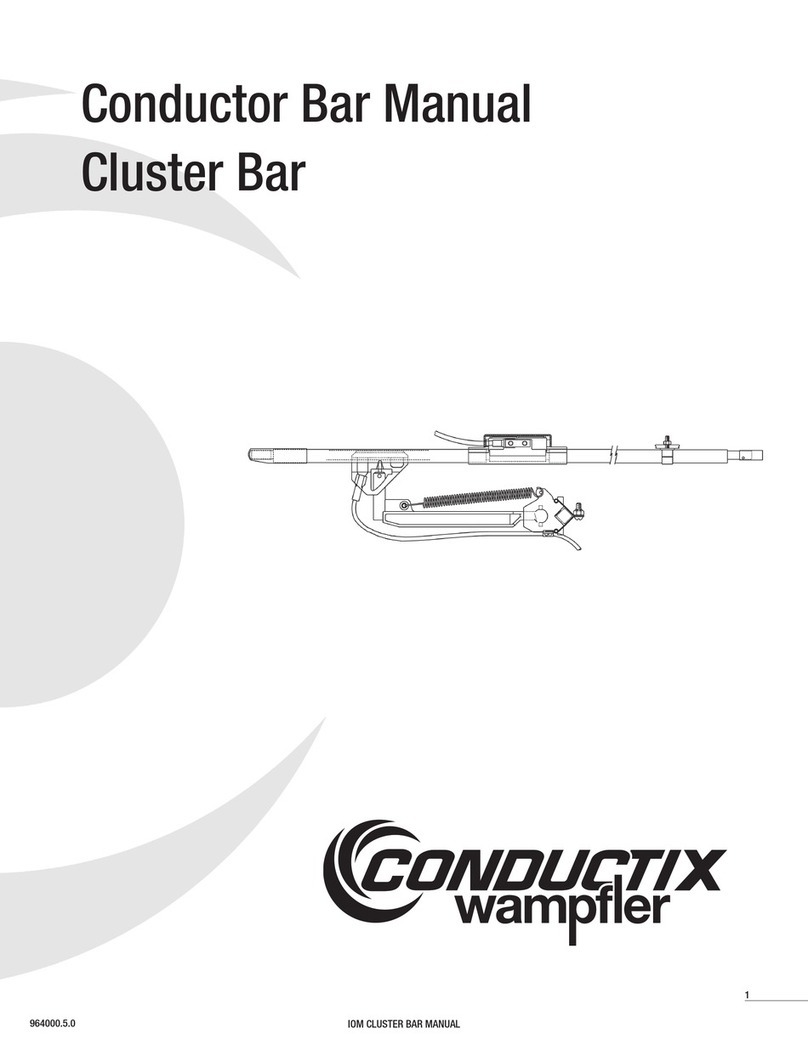
Conductix-Wampfler Conductor Bar User manual

Conductix-Wampfler

Conductix-Wampfler Conductor Bar User manual

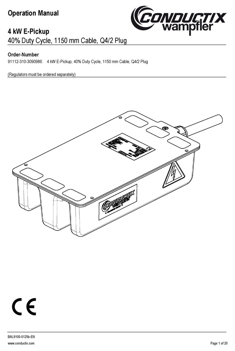
Conductix-Wampfler 91112-310-3090986 User manual

Conductix-Wampfler

Conductix-Wampfler 91112-310-3090986 User manual

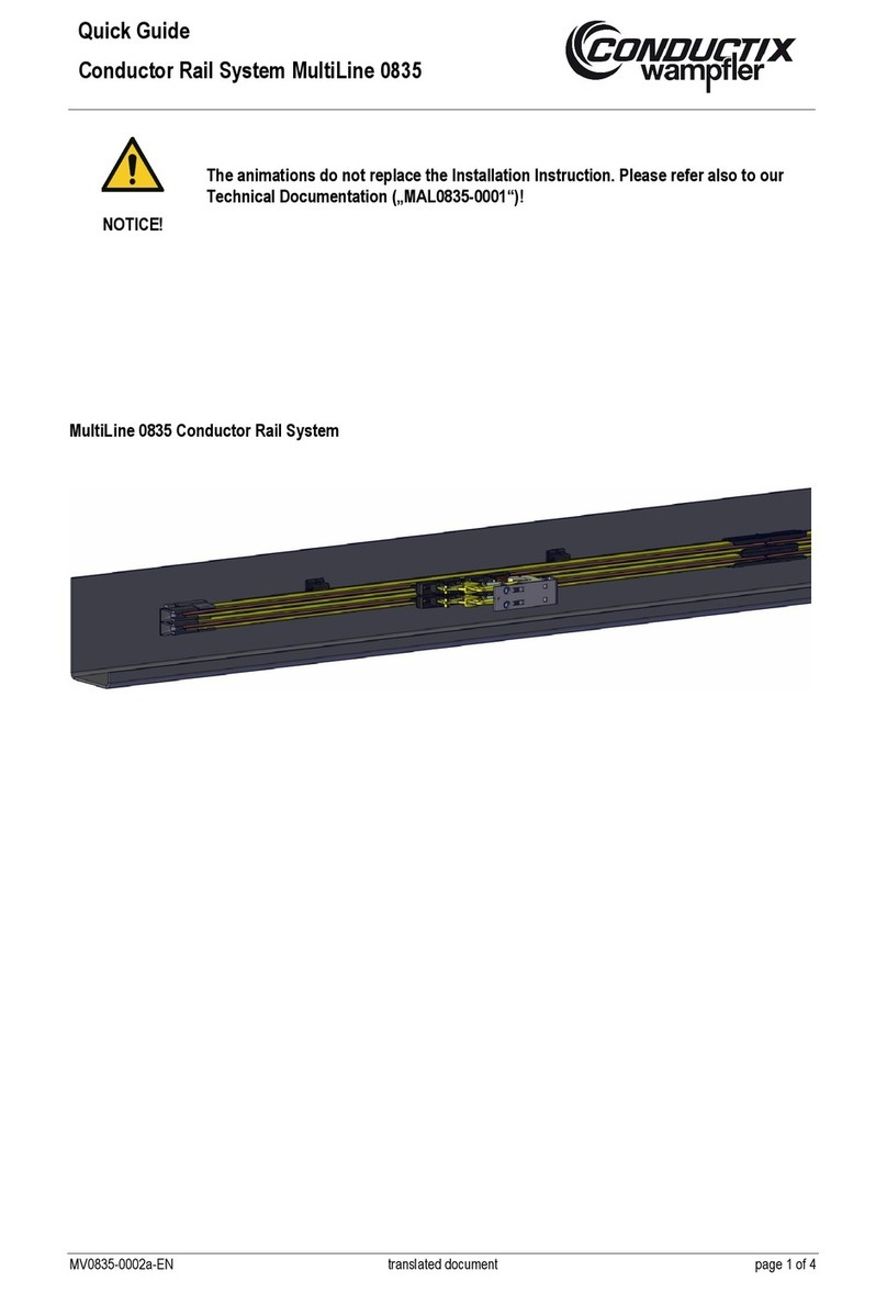
Conductix-Wampfler MultiLine 0835 User manual

Conductix-Wampfler

Conductix-Wampfler MultiLine 0835 User manual

Conductix-Wampfler 0365 User manual

Conductix-Wampfler

Conductix-Wampfler 0365 User manual

Conductix-Wampfler 0815 Series User manual

Conductix-Wampfler

Conductix-Wampfler 0815 Series User manual

Conductix-Wampfler MultiLine 0835 User guide

Conductix-Wampfler

Conductix-Wampfler MultiLine 0835 User guide

Conductix-Wampfler Enduro+ Series User manual

Conductix-Wampfler

Conductix-Wampfler Enduro+ Series User manual

Conductix-Wampfler 0832 User manual

Conductix-Wampfler

Conductix-Wampfler 0832 User manual

Conductix-Wampfler 1400 Series User manual

Conductix-Wampfler

Conductix-Wampfler 1400 Series User manual

Conductix-Wampfler SingleFlexLine Program 0815 User manual

Conductix-Wampfler

Conductix-Wampfler SingleFlexLine Program 0815 User manual

Conductix-Wampfler Hevi-Bar II User manual

Conductix-Wampfler

Conductix-Wampfler Hevi-Bar II User manual

Conductix-Wampfler 0832 User manual

Conductix-Wampfler

Conductix-Wampfler 0832 User manual

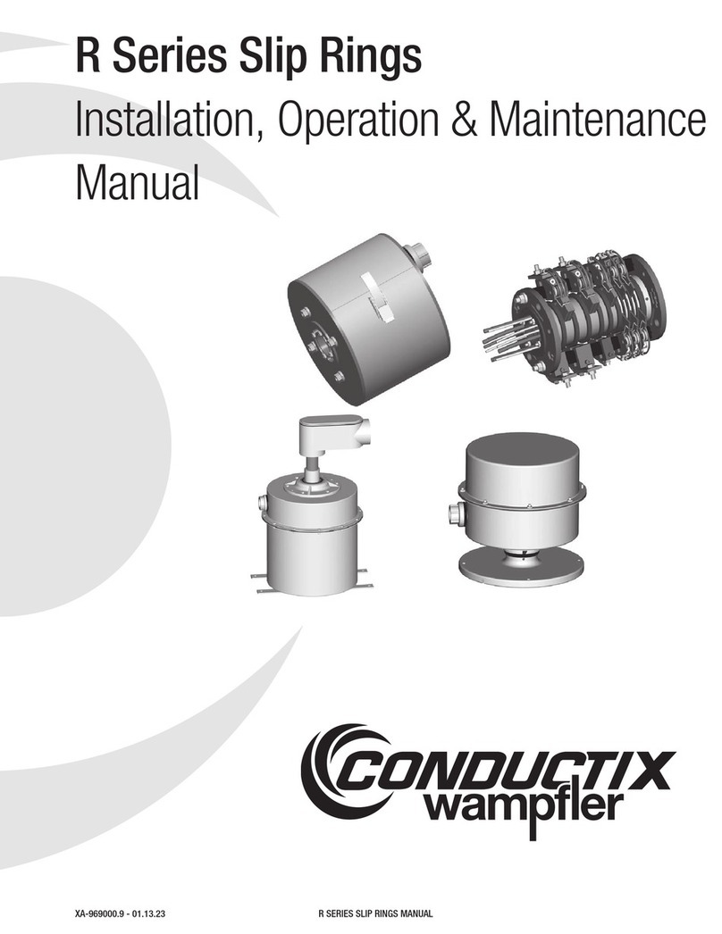
Conductix-Wampfler R Series Instruction manual

Conductix-Wampfler

Conductix-Wampfler R Series Instruction manual

Popular Industrial Equipment manuals by other brands

Intimus CR-460 ECP Product user manual

Intimus

Intimus CR-460 ECP Product user manual

Schmalz 10.01.11.02295 operating manual

Schmalz

Schmalz 10.01.11.02295 operating manual

Siemens SIMATIC NET Reference manual

Siemens

Siemens SIMATIC NET Reference manual

Netafim NETAFLEX 3G installation manual

Netafim

Netafim NETAFLEX 3G installation manual

Dirty Hand Tools 100171 Operation manual

Dirty Hand Tools

Dirty Hand Tools 100171 Operation manual

JUKI MEB-3200C instruction manual

JUKI

JUKI MEB-3200C instruction manual

MICRO-EPSILON surfaceCONTROL 3D SC2500 Assembly instructions

MICRO-EPSILON

MICRO-EPSILON surfaceCONTROL 3D SC2500 Assembly instructions

Clarke CSA10EP Operation & maintenance instructions

Clarke

Clarke CSA10EP Operation & maintenance instructions

WOOD'S POWR-GRIP MRT411LDC3 operating instructions

WOOD'S POWR-GRIP

WOOD'S POWR-GRIP MRT411LDC3 operating instructions

FIAMA SERVO.D User manual and maintenance

FIAMA

FIAMA SERVO.D User manual and maintenance

ABB HT844972 Operation manual

ABB

ABB HT844972 Operation manual

ABB Relion 615 series Quick installation guide

ABB

ABB Relion 615 series Quick installation guide

Tolomatic MXP63PTP quick start guide

Tolomatic

Tolomatic MXP63PTP quick start guide

StoneAge AUTOBOX ABX-3L-V3 user manual

StoneAge

StoneAge AUTOBOX ABX-3L-V3 user manual

DOUGHXPRESS DXP-CRS owner's manual

DOUGHXPRESS

DOUGHXPRESS DXP-CRS owner's manual

Kromschroeder GFK 65 operating instructions

Kromschroeder

Kromschroeder GFK 65 operating instructions

woodmizer MP260EA13U-V Safety, Setup, Operation, and Maintenance

woodmizer

woodmizer MP260EA13U-V Safety, Setup, Operation, and Maintenance

TECHLIGHTING ELEMENT E4-L A Series installation instructions

TECHLIGHTING

TECHLIGHTING ELEMENT E4-L A Series installation instructions

manuals.online logo
manuals.online logoBrands
  • About & Mission
  • Contact us
  • Privacy Policy
  • Terms and Conditions

Copyright 2025 Manuals.Online. All Rights Reserved.