TriangleTube INSRKIT124 User manual

Instinct
LP Update Kit
1
WARNING
!
Indicates a potentially hazardous situation which,
if ignored, can result in serious injury or substan-
tial property damage.
NOTICE
Indicates special instructions on installation, operation
or maintenance, which are important to equipment
but not related to personal injury hazards.
WARNING
!
For your safety, turn off electrical power supply
at service panel and allow unit to cool before pro-
ceeding to avoid possible electrical shock and
scald hazard. Failure to do so can cause severe
personal injury or death.
WARNING
!
Failure to follow instructions below can result in
severe personal injury or damage if ignored.
• Instructions are for a qualified installer/ ser-
vice technician only.
• Read all instructions before proceeding.
• Follow instructions in proper order.
Each Kit Includes:
• Control Module
• Display Module
• Venturi
• Venturi interface gasket
• Venturi/Blower Gasket
• Venturi screws
• Gas pipe gaskets
Recommended Tools:
• Phillips Head Screwdriver
• Combustion Analyzer
2022-01 LP Update Kit
Revised 1/18/2022
Kit Part Number Description Model
INSRKIT124 LP Update Kit Instinct 110 models
INSRKIT125 LP Update Kit Instinct 155 models
INSRKIT126 LP Update Kit Instinct 199 models

Instinct
LP Update Kit
2
1. Preliminary Instructions
1. Verify that the replacement kit is correct for the
model of boiler. See table on page 1.
2. Carefully open and unpack the PARTS BOX from its
shipping carton.
3. Carefully remove and check for any damage.
NOTICE
Installing a damaged equipment will cause malfunction of
the boiler. Contact Triangle Tube right away if the ontrol
module is damaged in any way.
WARNING
!
ELECTRICAL SHOCK HAZARD
Ensure power to the boiler has been disconnected pri-
or to servicing the unit.
4. Close the manual gas shut o valve to the unit.
Fig. 1: Instinct 110 Gas Train
Fig. 2: Instinct 155 Gas Train
Fig. 3: Instinct 199 Gas Train
2. Removal of old Venturi
1. Remove the silicone tube from the air inlet elbow,
then remove the air inlet elbow.
2. Rotate the venturi interface approximately 60°
clockwise to release the clamping mechanism and
remove the venturi interface. Discard the gasket
between the venturi and venturi interface.
3. Remove the gas valve to venturi pipe by loosening
the nuts at both ends of the pipe with an adjust-
able wrench.
4. Remove and dispose of the gasket installed at both
ends of the gas valve to venturi pipe. These gaskets
must be removed and replaced with new gaskets.
5. Using a 10 mm wrench, remove the three (3) bolts
securing the venturi to the fan assembly and re-
move the venturi from the unit.

Instinct
LP Update Kit
3
6. Remove and dispose of Blower/Venturi O-ring
3. Installation venturi
1. Verify the threaded connection for the gas piping is
in the correct orientation for re-tting the gas pipe.
2. Install the new Blower/Venturi O-ring into the
blower.
WARNING
!
Failure to install the new O-ring gasket between the
venturi and the blower will cause an improper seal re-
sulting in a potential risk of a gas leak. A gas leak can
result in substantial property damage, serious injury,
or death.
WARNING
!
Ensure the proper venturi for the model is installed.
Failure to comply will affect input rate and combus-
tion of the boiler which can result in substantial prop-
erty damage, serious injury, or death.
NOTICE
Do not use adhesive on any gaskets or O-rings during the re-
assembly process.
3. Using a 10 mm socket and ratchet, reinstall the
three (3) bolts securing the venturi to the fan as-
sembly
4. Reassemble the gas valve to venturi pipe to the
gas valve and venturi taking care to ensure that the
new gaskets are seated properly before tightening
the nut.
WARNING
!
Failure to install the new gas pipe gasket between the
venturi and the gas valve will cause an improper seal
resulting in a potential risk of a gas leak. A gas leak
can result in substantial property damage, serious in-
jury, or death
5. Install the new gasket and install the venturi inter-
face on the venturi and rotate counterclockwise
until locked into place.
6. Install the air inlet elbow then attach the silicone
tube.
WARNING
!
Failure to properly install the air inlet elbow and at-
tach the silicone tube will affect combustion of the
boiler which can result in substantial property dam-
age, serious injury, or death.
7. Open the manual gas shut o valve to the unit.
Before placing the boiler back into operation, test
all gas connections for leaks and repair if leaks are
found.
WARNING
!
Do not check for gas leaks with an open flame. Use a
bubble test. Failure to test for gas leaks can result in
substantial property damage, serious injury, or death.
4. Save Settings
NOTICE
Prior to replacing the control module and/or display module,
it is important to access and document the boiler’s settings.
This will ensure any settings revised from factory defaults are
transferred to the new module(s). Use Table 1 to record the
existing settings. Do not revise any settings when recording
settings.
1. To access the Installer screen, touching simultane-
ously the up and down soft keys for 3 seconds as
shown in Fig. 1.

Instinct
LP Update Kit
4
Fig. 4: Installer Button
2. Enter the installer access code “054” by using the
LEFT and RIGHT buttons to select a digit and the
UP and DOWN buttons to change the digit. Press
the OK button to enter the access code.
Fig. 5: Installer Access Code
3. Press the OK button while the CH & DHW Settings
icon is highlighted.
Fig. 6: CH & DHW Settings
4. Press the OK button while the CH Settings icon is
highlighted.
Fig. 7: CH Settings
5. Press the UP and DOWN buttons to scroll thru the
various settings.
Fig. 8: Heating Settings
6. Record all CH Settings in Table 1. Once completed,
press the RIGHT button to highlight the Previous
Screen icon, then press the OK button.
7. Press the RIGHT button to highlight the DHW Set-
tings icon then press the OK button.
Fig. 9: DHW Settings
8. Press the UP and DOWN buttons to scroll thru the
various settings and record all DHW Settings in Ta-
ble 1. Once completed, press the RIGHT button to
highlight the Previous Screen icon, then press the
OK button.

Instinct
LP Update Kit
5
Fig. 10: DHW Settings
9. Press the DOWN button to highlight the Boiler Set-
tings icon if present icon, then press the OK button.
10. Press the UP and DOWN buttons to scroll through
the various settings and record all Boiler Settings
in Table 1. Once completed, press the RIGHT but-
ton to highlight the Previous Screen icon, then
press the OK button.
NOTICE
Perform the following steps if the Instinct is part of a Cascade
System or the System Temperature Sensor is being used on a
single Instinct.
11. Press the RIGHT then DOWN buttons to highlight
the Previous Screen icon, then press the OK button.
12. Press the RIGHT then DOWN buttons to highlight
the Cascade icon, then press the OK button.
13. Press the RIGHT button to highlight the Cascade
Settings icon, then press the OK button.
14. Press the UP and DOWN buttons to scroll thru the
various settings, and record all Cascade Settings in
Table 1.
5. Remove Control Module
1. Remove the screw holding the metal shipping
bracket in place as shown in Fig. 8
Shipping
Bracket
Screw
Shipping
Bracket
Control
Module
Cover
Control
Module
Retaining Tab
Fig. 11: Control Module
2. Pull the retaining tab on top of the control module
case to remove the cover.
3. Record the current location of all plugs.
4. Remove all Molex wiring connectors from the
Control Module. Some plugs are equipped with a
locking clip. Squeeze the clip to unlock the plug.
Support Control Module with one hand while re-
moving individual Molex connectors. Press tabs on
Molex plugs for quick release.
5. Unclip the 1 clip on the side of the control module
and pull the module out.
6. Installation of Control Module
1. Mount the control module into the case by secure-
ing it behind the mounting clips on both sides of
the case.
2. Reconnect the Molex connectors to proper posi-
tion. Each connector is designed to t only in its re-
spective mating connector. If the plug is equipped
with a locking clip, ensure the clip is engaged.
3. Place the cover in place and lock in the top retain-
ing tab.
4. Remount the front jacket panel to the boiler.
5. Turn power to the unit “ON” and return the boiler
to service.
7. Replace Display Module

Instinct
LP Update Kit
6
NOTICE
The display module comes preinstalled in the front red dis-
play enclosure as shown in Fig. 8.
Fig. 12: Display Module
1. Remove the front jacket by removing the screw on
the bottom. Lift and remove the front cover. Do not
discard this screws as they will be reused.
2. Pull the retaining clip on top of the enclosure and
pull the front cover o.
3. Disconnect the yellow cables by squeezing the clip
on the back of the plug in and pulling rmly out
from the back of the display module. Use care not
to damage the plug.
4. Remove the rubber grommet holdind the yellow
cables from the old display ensloure.
5. Install the rubber grommet with the yellow cables
onto one of the tabs in the bottom of the new dis-
play ensloure.
6. Reconnect the yellow cables by pushing the plug
into the terminal. The clip on the back of the plug
will lock the plug into place. Use care not to dam-
age the cable or display module.
7. Close the front cover onto the back cover by insert-
ing the two tabs on the bottom of the front cover
into the appriopriate holes in the back cover and
close, engaging the tab in the top. Give the cover a
light tug to make sure the top retaining clip is tight.
8. Programming new Control Board
1. Follow the instructions in step 4 to gain access to
the installer menu.
2. Go to boiler settings and click appliance setting, as
seen in Fig. 9 and Fig. 10.
Fig. 13: Installer Menu
Fig. 14: Appliance setting
3. The required code is written on the data plate lo-
cated at the side of the boiler. Use the code for the
gas type, either Natural Gas or Propane.
4. Increase/decrease the value (from 0 to 9, then A to
Z) using the UP or DOWN keys to, then change po-
sition with the LEFT or RIGHT keys.
5. Follow the instructions on the screen to enter the
appliance code for your boiler.
6. The boiler will now be factory set for that particular
model. Return to step 2 and enter settings record-
ed in Table 1 back into the controls to return the
boiler to the customized settings of the old control.
7. Return to step 2 and enter settings recorded in Ta-
ble 1 back into the controls. Combustion Test and
Adjustments

Instinct
LP Update Kit
7
NOTICE
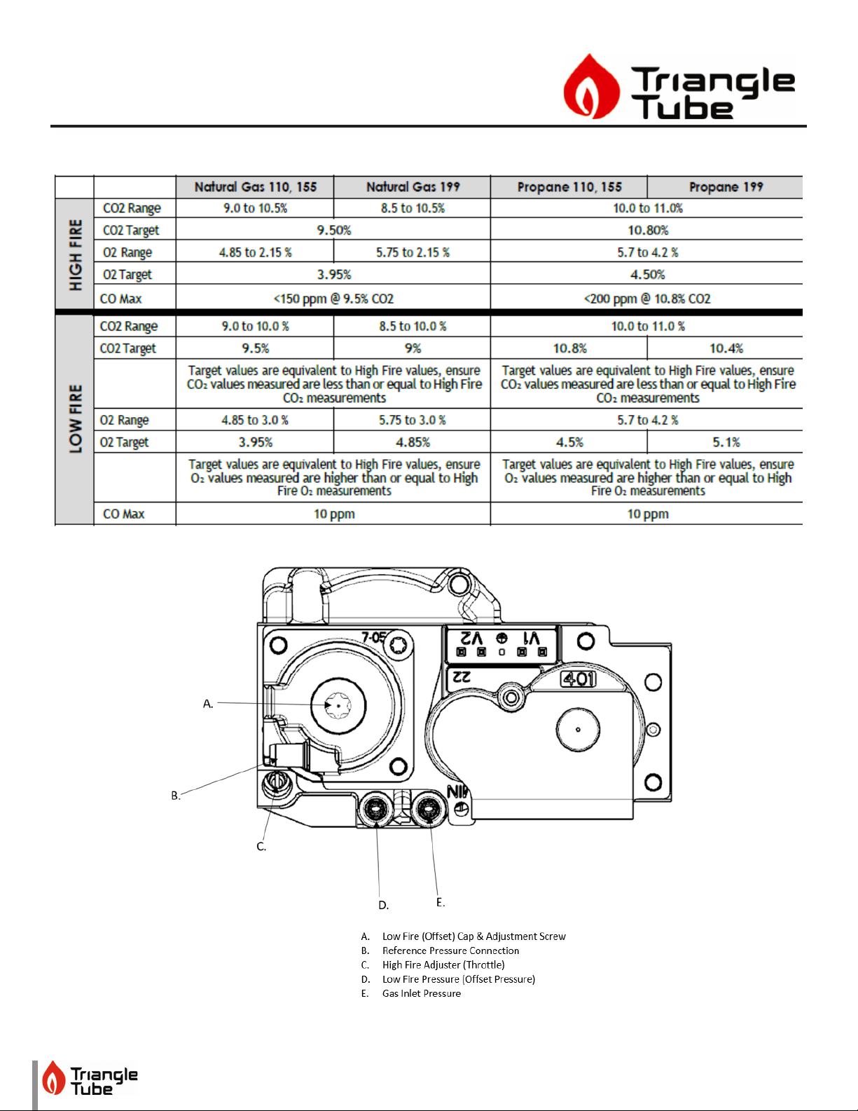
The installer MUST perform a complete combustion check
to ensure the following combustion levels are met at high
and low input ring rates and the burner is operating at op-
timum conditions.
WARNING
!
The combustion testing and adjustments must be per-
formed by a qualified installer, service agency or the
gas supplier. All combustion measurements must be
performed with calibrated equipment to ensure prop-
er readings and accuracy.
WARNING
!
Failure to perform a complete combustion test at both
high and low input rates may result in incomplete
combustion and the production of carbon monoxide,
which can cause severe personal injury, death or sub-
stantial property damage.
8. Touch simultaneously on the up and down soft
keys for 3 seconds to access the functions for the
installer. See Fig. 4.
9. Enter the installer access code “054” by using the
LEFT and RIGHT buttons to select a digit and the UP
and DOWN buttons to change the digit. Press the
CENTER button to enter the access code.
10. Press the RIGHT button to highlight the Manual
Operation icon then press the CENTER button.
Manual Operation
Released
O
O
O
CH1
FAN
DHW
CH2
Manual Operation
Released
O
O
O
CH1
FAN
DHW
CH2
Manual Operation
Released
O
O
O
CH2
FAN
DHW
CH1
Manual Operation
Released
O
O
O
DHW
FAN
CH1
CH2
Fig. 15: CTRLMax Manual Operation
11. Press the CENTER button while the FAN icon is
highlighted to manually re the burner and power
the CH circulator. See Fig. 5
NOTICE
An adequate CH load must be present to dissipate the heat
generated during the combustion test. If an adequate CH
load is not available, an indirect water heater can be used to
dissipate the heat by creating a DHW call which will enable
the DHW circulator.
12. Press the RIGHT button to adjust the ring rate to
100% (high re). Hold down the RIGHT button to
rapidly increase the ring rate.
13. If the combustion levels during high re are out-
side the recommended combustion settings (see
Table 1), adjust the THROTTLE SCREW (see Fig. 6)
using a at-blade screwdriver as follows:
Counter-clockwise adjustment of the THROTTLE
SCREW at High Fire (100% firing rate):
O2decreases and CO2 increases
Clockwise adjustment of the THROTTLE SCREW at
High Fire (100% firing rate):
O2increases and CO2decreases
14. Once the combustion level is set at high re, manu-
ally place the boiler into low re mode by pressing
the LEFT button to adjust ring rate down to 1%
(low re).
15. If the combustion level (O2or CO2) during low re
is not are outside the recommended combustion
settings in Table 1 contact Triangle Tube Technical
Support.
16. Press the CENTER button while the fan icon is high-
lighted to shutdown the burner.
17. Press the LEFT or RIGHT button to highlight the
home screen icon to exit the service mode.
18. Replace the front panel and put the boiler back
into operation.

Instinct
LP Update Kit
8
Table 1: Combustion Settings
Fig. 16: Throttle Screw Location

Instinct
LP Update Kit
9
Table 2: Controls Settings
HEATINGSETTING FACTORYDEFAULT MINIMUMSETTING MAXIMUMSETTING EXISTINGSETTING
Heating Operation Enabled
Demand Type Thermostat & Outd.
Curve
Absolute Max CH Setpoint 185°F [85°C] 68°F [20°C] 188°F [87°C]
CH1 Maximum Setpoint 180°F [82°C] 68°F [20°C] 188°F [87°C]
CH1 Minimum Setpoint 80°F [27°C] 60°F [15°C] 188°F [87°C]
Outdoor Curve Coldest Day 10°F [-12°C] -30°F [-34°C] 50°F [10°C]
Outdoor Curve Warmest Day 64°F [18°C] 60°F [15°C] 78°F [25°C]
CH2 Circuit Enabled
CH2 Maximum Setpoint 140°F [60°C] 68°F [20°C] 194°F [90°C]
CH2 Minimum Setpoint 80°F [27°C] 60°F [15°C] 190°F [88°C]
Warm Weather Shutdown O O 78°F [25°C]
Circulation Pump
Permanent
Disabled
CH Post Pump Time 5 Minutes O 20 Minutes
Freeze Protection Enabled
Frost Protection Setpoint -22°F [-30°C] -22°F [-30°C] 50°F [10°C]
Parallel Shift Value 0°F [0°C] 0°F [0°C] 144°F [80°C]
CH Call Blocking 2 Minutes 0 Minutes 30 Minutes
DOMESTICSETTING SOLO
FACTORY
DEFAULT
COMBI
FACTORY
DEFAULT
MINIMUM
SETTING
MAXIMUM
SETTING
EXISTING
SETTING
DHW Operation Enabled Enabled
Demand Type Thermostat N/A
DHW Boiler Setpoint 168°F [76°C] 168°F [76°C] 96°F [35°C] 188°F [87°C]
DHW Setpoint 140°F [60°C] 140°F [60°C] 68°F [20°C] 168F [75°C]
DHW Warmstart Setpoint N/A 125°F [52°C] 86°F [30°C] 140°F [60°C]
DHW Warmstart Hysteresis N/A 30°F [17K] 9K 36K
DHW On Dierential 6°F [3°C] N/A 4°F [2°C] 18°F [10°C]
DHW Storage Adder 27°F [15°C] 18°F [10°C] 10°F [5°C] 54°F [30°C]
DHW Post Pump Time 2 Minutes 2 Minutes O 30 Minutes
DHW Priority Timeout O O O 120 Minutes
DHW Priority Enabled Enabled
DHW Call Blocking 1 Minute 1 Minute 0 Minute 30 Minutes
DHW to CH Call Blocking 1 Minute 1 Minute 0 Minute 30 Minutes
Antilegionella Function Disabled Enabled

Instinct
LP Update Kit
10
Table 1 Cont:
BOILERSETTING FACTORYDEFAULT MINIMUMSETTING MAXIMUMSETTING EXISTINGSETTING
Lockout Temp. 210°F [99°C]
Modbus Address 0=BCST 0=BCST 247
Flex. Relay 1(CH) CH1
Flex. Relay 2(DHW) DHW
Flex. Relay 3(P3) CH1/CH2/DHW
Flex. Relay 4(ERR) ERROR
Flex. Relay 5(Flame) FLAME
Flex. Relay 6(P4) CH2
Error Relay On Lockout, Blocking
andWarning
Pump PWM Minimum 30% 1% 100%
Ignition Level Varies by model
Mix Zone High Limit 114°F [45°C] 68°F [20°C] 176°F [80°C]
Appliance Setting Varies by model
Altitude Setting 0 ft 0 ft 20,000 ft
This manual suits for next models
5
Table of contents
Other TriangleTube Industrial Equipment manuals

TriangleTube
TriangleTube MAXI-FLO MF-135 Manual

TriangleTube
TriangleTube TTP Series User manual

TriangleTube
TriangleTube MAXI-FLO MF 350 PT Series Manual

TriangleTube
TriangleTube Instinct 110 User manual

TriangleTube
TriangleTube PRESTIGE Excellence Series User manual

TriangleTube
TriangleTube PSRKIT25 User manual
Popular Industrial Equipment manuals by other brands

National Instruments
National Instruments NI-9230 Getting started

HSB
HSB Alpha 15-B-155 Original Assembly and Maintenance Manual

Vortec
Vortec AIR KNIVES Operation & Safety Instructions

Enerpac
Enerpac CLL instruction sheet

Greenlee
Greenlee FS439-100 instruction manual

hyfire
hyfire HFW-CEM-02 quick start guide