manuals.online logo
Brands
  1. Home
  2. •
  3. Brands
  4. •
  5. Clarke
  6. •
  7. Floor Machine
  8. •
  9. Clarke MA50 15B User manual

Clarke MA50 15B User manual

Electronic Service
Manuals
This electronic document is provided as a service to our customers.
Wedonotcreatethecontentsoftheinformationcontainedinthisdocu-
ment. Shouldyouhavedetailedquestionspertainingtotheinformation
contained in this document, you may contact Michco, or the manufac-
turer which provided the original information in this electronic deliver-
able. Michco’sonlypartin this electronic deliverable was the electronic
assemblyprocess. Byprovidingthismanualonlinewearenotguaran-
teeing parts availability.
You may contact Michco through the following methods:
Phone (517) 484-9312 or (800) 331-3339
2011 N. High St. -- Lansing, Michigan -- 48906
Fax: (517) 484-9836
Email: [email protected]
Web site: www.Michco.Com
Parts Web site: www.FloorMachineParts.Com
Order Parts on Line at:
www.FloorMachineParts.Com
Directly to Parts & Service:
By Email: [email protected]
By Fax: (517) 702-2041
By Voice: Use numbers above.
Serving the Cleaning Industry Since 1922
Notice: All copyrighted material remains property of original owners, all trademarks are property of respective owners.
ManualsaresubjecttoManufacturer’sreproductionlimitations. Originalsorreproductionswereprovidedbymanufacturers
through a request. We make no warranty as to the correctness of information provided in this document and you assume
allrisk. By placing thesemanualsonlinewe are notdeclaringourcorporation to be anmanufacturerauthorizeddealer or
provider, please check ourwebsiteforauthorizedmanufacturerswerepresent.
Clarke MA50 15B™
03/2016 - Form No. 56043172
Service Manual
Model Numbers:
Clarke MA50 15B
English
Table of Contents iiService Manual – MA50 15B
Contents
Service Manual . . . . . . . . . . . . . . . . . . . . . . . . . . . . . . . . . . . . . . . . 1
General Information . . . . . . . . . . . . . . . . . . . . . . . . . . . . . . . . . . . . . 4
Machine Description . . . . . . . . . . . . . . . . . . . . . . . . . . . . . . . . . . . . . 4
Service Manual Purpose . . . . . . . . . . . . . . . . . . . . . . . . . . . . . . . . . . . 4
Revision History . . . . . . . . . . . . . . . . . . . . . . . . . . . . . . . . . . . . . . . 4
Other Reference Manuals . . . . . . . . . . . . . . . . . . . . . . . . . . . . . . . . . . 4
Diagnostic and Service tools . . . . . . . . . . . . . . . . . . . . . . . . . . . . . . . . . 4
Conventions . . . . . . . . . . . . . . . . . . . . . . . . . . . . . . . . . . . . . . . . . 5
Parts and Service. . . . . . . . . . . . . . . . . . . . . . . . . . . . . . . . . . . . . . . 5
Modications . . . . . . . . . . . . . . . . . . . . . . . . . . . . . . . . . . . . . . . . . 5
Machine Lifting . . . . . . . . . . . . . . . . . . . . . . . . . . . . . . . . . . . . . . . 5
Machine Transportation . . . . . . . . . . . . . . . . . . . . . . . . . . . . . . . . . . . 5
General Safety Instructions . . . . . . . . . . . . . . . . . . . . . . . . . . . . . . . . . 5
Nameplate . . . . . . . . . . . . . . . . . . . . . . . . . . . . . . . . . . . . . . . . . . 6
Machine Specications. . . . . . . . . . . . . . . . . . . . . . . . . . . . . . . . . . . . 6
Component Locations . . . . . . . . . . . . . . . . . . . . . . . . . . . . . . . . . . . . 7
Preventative Maintenance . . . . . . . . . . . . . . . . . . . . . . . . . . . . . . . . . .10
Options and Accessories . . . . . . . . . . . . . . . . . . . . . . . . . . . . . . . . . . 11
Pad Driver . . . . . . . . . . . . . . . . . . . . . . . . . . . . . . . . . . . . . . . . . . 11
Squeegee Blades . . . . . . . . . . . . . . . . . . . . . . . . . . . . . . . . . . . . . . . 11
Control System . . . . . . . . . . . . . . . . . . . . . . . . . . . . . . . . . . . . . . . 12
Functional Description. . . . . . . . . . . . . . . . . . . . . . . . . . . . . . . . . . . .12
Component Locations . . . . . . . . . . . . . . . . . . . . . . . . . . . . . . . . . . . . 12
Maintenance and Adjustment . . . . . . . . . . . . . . . . . . . . . . . . . . . . . . . . 16
Electrical System . . . . . . . . . . . . . . . . . . . . . . . . . . . . . . . . . . . . . . 17
Functional Description. . . . . . . . . . . . . . . . . . . . . . . . . . . . . . . . . . . .17
Component Locations . . . . . . . . . . . . . . . . . . . . . . . . . . . . . . . . . . . . 18
Wiring Harness Diagram . . . . . . . . . . . . . . . . . . . . . . . . . . . . . . . . . .20
Battery Connections . . . . . . . . . . . . . . . . . . . . . . . . . . . . . . . . . . . . . 21
Battery Charging. . . . . . . . . . . . . . . . . . . . . . . . . . . . . . . . . . . . . . .21
Battery Charging Procedure . . . . . . . . . . . . . . . . . . . . . . . . . . . . . . 21
Battery Charging Notes . . . . . . . . . . . . . . . . . . . . . . . . . . . . . . . . .22
Removal and Installation . . . . . . . . . . . . . . . . . . . . . . . . . . . . . . . . . . 22
On-Board Charger . . . . . . . . . . . . . . . . . . . . . . . . . . . . . . . . . . . . 22
Control PCB . . . . . . . . . . . . . . . . . . . . . . . . . . . . . . . . . . . . . . . 24
Basic Troubleshooting . . . . . . . . . . . . . . . . . . . . . . . . . . . . . . . . . . . .26
Troubleshooting Tips. . . . . . . . . . . . . . . . . . . . . . . . . . . . . . . . . . . . .26
Shop Measurements . . . . . . . . . . . . . . . . . . . . . . . . . . . . . . . . . . . . .26
Handle System . . . . . . . . . . . . . . . . . . . . . . . . . . . . . . . . . . . . . . . 29
Functional Description. . . . . . . . . . . . . . . . . . . . . . . . . . . . . . . . . . . .29
Component Locations . . . . . . . . . . . . . . . . . . . . . . . . . . . . . . . . . . . . 29
Removal and Replacement. . . . . . . . . . . . . . . . . . . . . . . . . . . . . . . . . .33
Switch PCB. . . . . . . . . . . . . . . . . . . . . . . . . . . . . . . . . . . . . . . .33
Triggers and Trigger Switch . . . . . . . . . . . . . . . . . . . . . . . . . . . . . .35
Handle Adjust Cable and Gears. . . . . . . . . . . . . . . . . . . . . . . . . . . . .37
Recovery System . . . . . . . . . . . . . . . . . . . . . . . . . . . . . . . . . . . . . . 44
Functional Description. . . . . . . . . . . . . . . . . . . . . . . . . . . . . . . . . . . .44
Circuit Description . . . . . . . . . . . . . . . . . . . . . . . . . . . . . . . . . . . . . .44
Component Locations . . . . . . . . . . . . . . . . . . . . . . . . . . . . . . . . . . . . 44
Maintenance and Adjustment . . . . . . . . . . . . . . . . . . . . . . . . . . . . . . . . 48
Table of Contents iiiService Manual – MA50 15B
Check ball-oat operation . . . . . . . . . . . . . . . . . . . . . . . . . . . . . . . . 48

Troubleshooting . . . . . . . . . . . . . . . . . . . . . . . . . . . . . . . . . . . . . . . 48
Poor pick-up at squeegee . . . . . . . . . . . . . . . . . . . . . . . . . . . . . . . . 49
Removal and Installation . . . . . . . . . . . . . . . . . . . . . . . . . . . . . . . . . . 49
Vacuum motor . . . . . . . . . . . . . . . . . . . . . . . . . . . . . . . . . . . . . .49
Removal: . . . . . . . . . . . . . . . . . . . . . . . . . . . . . . . . . . . . . . . 49
Installation: . . . . . . . . . . . . . . . . . . . . . . . . . . . . . . . . . . . . . 52
Vacuum Seals . . . . . . . . . . . . . . . . . . . . . . . . . . . . . . . . . . . . . .53
Vacuum Motor Switch . . . . . . . . . . . . . . . . . . . . . . . . . . . . . . . . . .54
Control PCB . . . . . . . . . . . . . . . . . . . . . . . . . . . . . . . . . . . . . . . 54
Specications . . . . . . . . . . . . . . . . . . . . . . . . . . . . . . . . . . . . . . . . .54
Shop Measurements . . . . . . . . . . . . . . . . . . . . . . . . . . . . . . . . . . . . .54
Scrub System . . . . . . . . . . . . . . . . . . . . . . . . . . . . . . . . . . . . . . . . 55
Functional Description. . . . . . . . . . . . . . . . . . . . . . . . . . . . . . . . . . . .55
Circuit Description . . . . . . . . . . . . . . . . . . . . . . . . . . . . . . . . . . . . . .55
Component Locations . . . . . . . . . . . . . . . . . . . . . . . . . . . . . . . . . . . . 55
Troubleshooting . . . . . . . . . . . . . . . . . . . . . . . . . . . . . . . . . . . . . . . 60
Removal and Installation . . . . . . . . . . . . . . . . . . . . . . . . . . . . . . . . . . 60
Drive Belt . . . . . . . . . . . . . . . . . . . . . . . . . . . . . . . . . . . . . . . . 60
Brush Motor . . . . . . . . . . . . . . . . . . . . . . . . . . . . . . . . . . . . . . . 61
Shop Measurements . . . . . . . . . . . . . . . . . . . . . . . . . . . . . . . . . . . . .65
Solution System . . . . . . . . . . . . . . . . . . . . . . . . . . . . . . . . . . . . . . 66
Functional Description. . . . . . . . . . . . . . . . . . . . . . . . . . . . . . . . . . . .66
Circuit Description . . . . . . . . . . . . . . . . . . . . . . . . . . . . . . . . . . . . . .66
Component Locations . . . . . . . . . . . . . . . . . . . . . . . . . . . . . . . . . . . . 67
Maintenance and Adjustment . . . . . . . . . . . . . . . . . . . . . . . . . . . . . . . . 69
Flushing Solution Tank . . . . . . . . . . . . . . . . . . . . . . . . . . . . . . . . . 69
Troubleshooting . . . . . . . . . . . . . . . . . . . . . . . . . . . . . . . . . . . . . . . 69
Removal and Installation . . . . . . . . . . . . . . . . . . . . . . . . . . . . . . . . . . 70
Solution Solenoid . . . . . . . . . . . . . . . . . . . . . . . . . . . . . . . . . . . .70
Solution Flow control valve . . . . . . . . . . . . . . . . . . . . . . . . . . . . . . . 72
Solution Switch . . . . . . . . . . . . . . . . . . . . . . . . . . . . . . . . . . . . . 72
Control PCB . . . . . . . . . . . . . . . . . . . . . . . . . . . . . . . . . . . . . . . 73
Squeegee System . . . . . . . . . . . . . . . . . . . . . . . . . . . . . . . . . . . . . . 76
Functional Description. . . . . . . . . . . . . . . . . . . . . . . . . . . . . . . . . . . .76
Maintenance and Adjustment. . . . . . . . . . . . . . . . . . . . . . . . . . . . . . . .79
Adjusting the Squeegee down pressure . . . . . . . . . . . . . . . . . . . . . . . . .79
Removal and Installation . . . . . . . . . . . . . . . . . . . . . . . . . . . . . . . . . . 80
Squeegee Lift Cable . . . . . . . . . . . . . . . . . . . . . . . . . . . . . . . . . . . 80
Squeegee Blades . . . . . . . . . . . . . . . . . . . . . . . . . . . . . . . . . . . . . 84
Troubleshooting . . . . . . . . . . . . . . . . . . . . . . . . . . . . . . . . . . . . . . . 86
General Information 4Service Manual – MA50 15B
General Information
Machine Description
The CLARKE MA50 15B is a battery powered walk-behind automatic oor scrubber. It is intended for use in small
to medium size commercial facilities such as retail stores.
The CLARKE MA50 15B is equipped with a rotating brush to provide a 15 inch cleaning path.
The machine has (2) 12 volt AGM batteries connected in series to provide 24 volts DC to the vacuum motor, brush
motor and other systems.
The CLARKE MA50 15B is equipped with an on-board charger for the batteries. No external charger is required.
Service Manual Purpose
The service manual is a resource for professional service technicians. It provides information for understanding
how the machine operates, where components are located, basic troubleshooting, maintenance, and mechanical
service operations.
Revision History
Date Revisions
3/16 Initial publication
Other Reference Manuals
Operators manual (Includes Parts List Information) - Form number VF89027
Diagnostic and Service tools
In addition to a full set of metric and standard tools, the following are required to successfully and quickly
troubleshoot and repair CLARKE commercial oor cleaning equipment.
• Digital Voltmeter (DVM) with current clamp
• Battery load tester for checking batteries
• Vacuum water lift gauge - Nilsk p/n 56205281
General Information 5Service Manual – MA50 15B
Conventions
Forward, backward, front, rear, left or right are intended with reference to the operator’s position. That is to say, in
the driving position, holding onto the handles on the control housing.
Parts and Service
Repairs should be performed by an Authorized Nilsk Service Center that employs factory-trained service
personnel and maintains an inventory of Nilsk original replacement parts and accessories.
Call the Nilsk Dealer for repair parts or service. Please specify the Model Number (same as the Part Number)
and Serial Number when discussing your machine.
Modications
Modications and additions to the cleaning machine which affect capacity and safe operation shall not be
performed by the customer or user without prior written approval Nilsk Inc. Unapproved modications will void
the machine warranty and make the customer liable for any resulting accidents.
Machine Lifting
The Clarke MA50 15B weighs 124 pounds with the batteries installed. Use (2) people to lift and/or carry the
machine. The Clarke MA50 15B should not be lifted by any other means (i.e. dolly, forklift).
Machine Transportation
The Clarke MA50 15B should only be rolled on smooth oors. Do not roll the machine down stairs or curbs.
Warning: Damage to the machine will occur if it is rolled down stairs or curbs !
General Safety Instructions
Warning! Be sure to follow these safety precautions to avoid situations that could cause severe personal injury.
• This machine should only be used by properly-trained and authorized personnel.
• This machine is not intended for use by persons (including children) with reduced physical, sensory or mental
capabilities, or lack of experience and knowledge.
• Turn the machine “OFF” and disconnect the batteries before servicing electrical components.
• Do not dispense ammable cleaning agents, operate the machine on or near these agents, or operate in areas
where ammable liquids exist.
• Do not clean this machine with a pressure washer.
General Information 6Service Manual – MA50 15B
Nameplate
The nameplate contains important identication information which will be needed when ordering parts: Model
number, Description, and Serial number.
Machine Specications
Specication USA Metric
Cleaning Path 15 Inches 380 Cm
Solution Tank 3.5 Gallons 13.5 Liters
Recovery Tank 3.5 Gallons 13.5 Liters
Brush/Pad Pressure 44.5 Pounds 20 Kg
Squeegee 20 Inches 51 Cm
Drive System Pad Assist Pad Assist
Brush Motor, RPM Speed 1/3 H.P., 150 RPM .25Kw, 150 RPM
Vacuum Motor, Waterlift 1/3/ H.P., 40 Inches waterlift .25 Kw, 100 Cm waterlift
Sound Level 70 dba 70 dba
Batteries, Sealed, AGM (2) 12 volt, 33 amp/hour (2) 12 volt, 33 amp/hour
Charger, On-Board 24 volts DC, 5 amp 24 volts DC, 5 amp
RunTime per Charge Up to (2) hours Up to (2) hours
Machine Weight 124 Pounds 56 Kg
Machine Dimensions 30 In x 20 In x 21.7 In 77 cm x 50 cm x 55 cm
General Information 7Service Manual – MA50 15B
Component Locations
Recovery
Tank
Recovery Tank
Lid
Brush Deck
Solution Fill
Hole
Solution Tank
ON/OFF
switch Brush
switch Vacuum
switch Solution
switch
General Information 8Service Manual – MA50 15B
Solution Control
Valve Squeegee
Assembly Brush
Solution Tank Drain
Cap
Recovery Tank
Drain cap
General Information 9Service Manual – MA50 15B
Operating Triggers
Handle Adjust Lever
Squeegee Lift
Handle
Squeegee Lift
Cable
General Information 10Service Manual – MA50 15B
Preventative Maintenance
DAILY WEEKLY MONTHLYMonthly
Recharge Batteries X
Remove and clean Pad driver/
Brush X
Drain and rinse recovery tank.
Check for solid debris X
Remove squeegee assembly,
and wipe it down with a damp
cloth X
Remove the oat shut-off and
rinse thoroughly X
Clean off the machine with a
damp towel X
Check batteries for loose or
corroded connections X
Check Squeegee blades for wear
and/or damage X
Check machine for leaks and
loose fasteners X
Lubricate all pivot points with a
silicone Spray X
Thoroughly ush the solution
tank, drain hose, and vacuum
hose with hot water X
Options and Accessories 11Service Manual – MA50 15B
Options and Accessories
Pad Driver
The Clarke MA50 15B comes standard with a medium duty brush. An optional pad driver can be ordered through
your Nilsk dealer.
Squeegee Blades
The Clarke MA50 15B comes standard with neoprene rubber squeegee blades. Optional polyurethane blades
can be ordered through your Nilsk dealer.
Polyurethane Rear Blade
Polyurethane Front Blade
Control System 12Service Manual – MA50 15B
Control System
Functional Description
The CLARKE MA50 15B has (1) Control PCB for the vacuum and brush circuits, and for the on-board charger
interlock system. .The Control PCB gets input from the batteries, the on-board charger, and the switch PCB.
Outputs from the Control PCB are to the vacuum and brush motors, the solution valve, the on-board charger, and
the indicator LED’s on the switch panel.
The solution ow is controlled by a manually adjusted valve.
The Vacuum motor and Brush motor are each protected by a circuit breaker.
Component Locations
• System Switches
• Triggers and Trigger switch
• Solution Control Valve
• Solution Solenoid
• Circuit breakers
• On-Board Charger Plug socket and LED display lights
• On-Board Charger and Control PCB
Power Switch Brush Switch Vacuum Switch Solution Switch
Control System 13Service Manual – MA50 15B
Triggers
Viewed inside control housing
Triggers
Trigger switch
Control System 14Service Manual – MA50 15B
Solution Control Valve
Solution Solenoid
Control System 15Service Manual – MA50 15B
Shown with Handle removed from machine, and cover
removed from Circuit box
On-Board
Charger Control PCB
Circuit Breakers
On-Board
Charger
Plug
On-Board
Charger
Indicator
lights
Control System 16Service Manual – MA50 15B
Maintenance and Adjustment
No maintenance or adjustment is required for the control system
Electrical System 17Service Manual – MA50 15B
Electrical System
Functional Description
The electrical system consists of a switch panel, and a control PCB to operate the vacuum and brush motors and
solution solenoid. There are also (2) circuit breakers which are used to protect the vacuum and brush motor from
excessive current.
The battery charger is an “on board” style charger which is 24 volts DC, and has an output of 5 amps maximum.
The electrical system is powered by (2) 12-volt batteries for a total of 24 volts. Heavy wires connect the batteries
in series. The battery charger has an interlock to prevent charging when the machine is powered up. There is no
need to dis-connect the batteries for charging.
The control system will turn off the scrub system and recovery systems if the battery voltage drops too low to
prevent damage to the batteries due to excessive discharging.
The machine wiring is color coded, and the wires are marked with yellow numbered bands corresponding to their
location on the Wiring Harness Diagram.
Electrical System 18Service Manual – MA50 15B
Component Locations
• Batteries
• Battery Connector
• Switch panel
• Circuit Breakers
• Charger plug and LED’s
• Charger
• Control PCB
(2) 12 volt batteries
wired in series
Battery Connector
Switch Panel
Switch PCB behind
label
Electrical System 19Service Manual – MA50 15B
On-Board
Charger Control PCB
On-Board Charger
Plug
On-Board Charger
LED Indicator
lights
Circuit Breakers

Other Clarke Floor Machine manuals

Clarke 59229A Installation and maintenance instructions

Clarke

Clarke 59229A Installation and maintenance instructions

Clarke FOCUS II MICRO RIDER 26D User manual

Clarke

Clarke FOCUS II MICRO RIDER 26D User manual

Clarke FOCUS L17 User manual

Clarke

Clarke FOCUS L17 User manual

Clarke Vantage 17 cable User manual

Clarke

Clarke Vantage 17 cable User manual

Clarke CA90 32T User manual

Clarke

Clarke CA90 32T User manual

Clarke BOS-18 User manual

Clarke

Clarke BOS-18 User manual

Clarke Image 26B User manual

Clarke

Clarke Image 26B User manual

Clarke CFP Pro 17HD User manual

Clarke

Clarke CFP Pro 17HD User manual

Clarke MA30 13 B 9087383020 User manual

Clarke

Clarke MA30 13 B 9087383020 User manual

Clarke Carpetmaster 577 User manual

Clarke

Clarke Carpetmaster 577 User manual

Clarke Alto Vision 17E User manual

Clarke

Clarke Alto Vision 17E User manual

Clarke FM-1700 User manual

Clarke

Clarke FM-1700 User manual

Clarke Mini-Max 26 User manual

Clarke

Clarke Mini-Max 26 User manual

Clarke Clean Track L24 56317170 User manual

Clarke

Clarke Clean Track L24 56317170 User manual

Clarke IMAGE 16 I User manual

Clarke

Clarke IMAGE 16 I User manual

Clarke Focus II User manual

Clarke

Clarke Focus II User manual

Clarke EX30 500H User manual

Clarke

Clarke EX30 500H User manual

Clarke RSW 37 User manual

Clarke

Clarke RSW 37 User manual

Clarke FOCUS II MICRO RIDER 26D User manual

Clarke

Clarke FOCUS II MICRO RIDER 26D User manual

Clarke Clean Track 18 Wash Rinse User manual

Clarke

Clarke Clean Track 18 Wash Rinse User manual

Clarke 3DS User manual

Clarke

Clarke 3DS User manual

Clarke Ultra Speed Burnisher User manual

Clarke

Clarke Ultra Speed Burnisher User manual

Clarke FA-8 User manual

Clarke

Clarke FA-8 User manual

Clarke Vantage 17 cable User manual

Clarke

Clarke Vantage 17 cable User manual

Popular Floor Machine manuals by other brands

Schwamborn ES 330 Translation of the original operating manual

Schwamborn

Schwamborn ES 330 Translation of the original operating manual

Nilfisk-Advance SC500 9087352020 Instructions for use

Nilfisk-Advance

Nilfisk-Advance SC500 9087352020 Instructions for use

Tennant 810 Gas Operator's manual

Tennant

Tennant 810 Gas Operator's manual

Tennant 355E Operator's manual

Tennant

Tennant 355E Operator's manual

Windsor CLP12 Operator instructions

Windsor

Windsor CLP12 Operator instructions

Superabrasive Lavina 30L Pro user manual

Superabrasive

Superabrasive Lavina 30L Pro user manual

Windsor Voyager 2 VGR2 operating instructions

Windsor

Windsor Voyager 2 VGR2 operating instructions

Tornado MARATHON 2000 Operation & service manual

Tornado

Tornado MARATHON 2000 Operation & service manual

Advance acoustic 56380772 Instructions for use

Advance acoustic

Advance acoustic 56380772 Instructions for use

BETCO FOREMAN 20 HD Operator's manual

BETCO

BETCO FOREMAN 20 HD Operator's manual

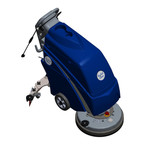
Trusted Clean TPL-BK-17-TC Owner's/operator's manual

Trusted Clean

Trusted Clean TPL-BK-17-TC Owner's/operator's manual

Cleanfix Eagle RA 700 B Safety, Operations & Maint. Manual

Cleanfix

Cleanfix Eagle RA 700 B Safety, Operations & Maint. Manual

Onfloor PRO SERIES 16 Safety, operation manual & parts list

Onfloor

Onfloor PRO SERIES 16 Safety, operation manual & parts list

Taski ergodisc omni Instructions of use

Taski

Taski ergodisc omni Instructions of use

NSS WRANGLER 20 E manual

NSS

NSS WRANGLER 20 E manual

Flextool ART-CUB operating instructions

Flextool

Flextool ART-CUB operating instructions

Koblenz SP-15 Operating and service instructions

Koblenz

Koblenz SP-15 Operating and service instructions

Tornado Floor Finishing Machine operation instruction

Tornado

Tornado Floor Finishing Machine operation instruction

manuals.online logo
manuals.online logoBrands
  • About & Mission
  • Contact us
  • Privacy Policy
  • Terms and Conditions

Copyright 2025 Manuals.Online. All Rights Reserved.