manuals.online logo
Brands
  1. Home
  2. •
  3. Brands
  4. •
  5. Clarke
  6. •
  7. Sander
  8. •
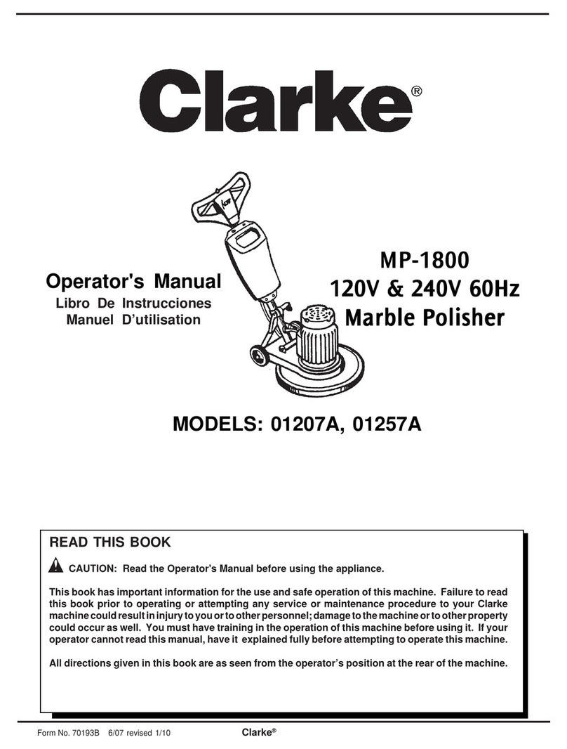
  9. Clarke 07097A User manual

Clarke 07097A User manual

Other manuals for 07097A

1

This manual suits for next models

2

Other Clarke Sander manuals

Clarke Super 7R User manual

Clarke

Clarke Super 7R User manual

Clarke 07032C User manual

Clarke

Clarke 07032C User manual

Clarke CMS 200 Instruction Manual

Clarke

Clarke CMS 200 Instruction Manual

Clarke X-Pro CAT168 Installation and operation manual

Clarke

Clarke X-Pro CAT168 Installation and operation manual

Clarke CS69D Instruction Manual

Clarke

Clarke CS69D Instruction Manual

Clarke 01207SD User manual

Clarke

Clarke 01207SD User manual

Clarke air CAT25B Installation and operation manual

Clarke

Clarke air CAT25B Installation and operation manual

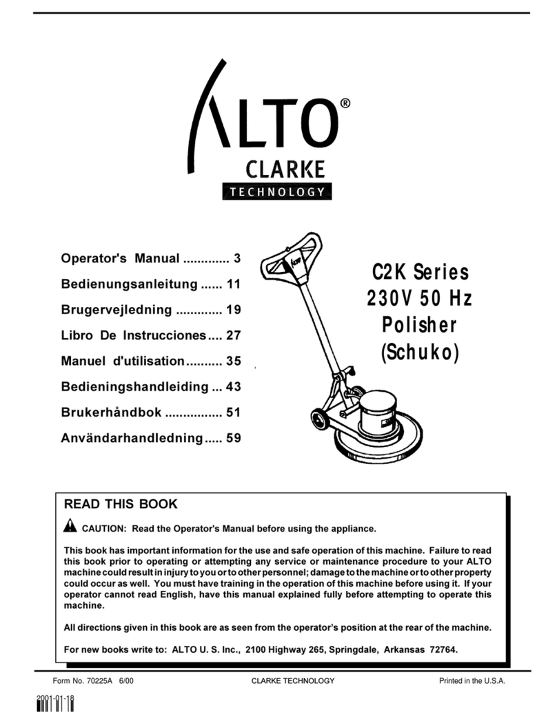
Clarke ALTO C2K Series User manual

Clarke

Clarke ALTO C2K Series User manual

Clarke CP150 Troubleshooting guide

Clarke

Clarke CP150 Troubleshooting guide

Clarke 07163A User manual

Clarke

Clarke 07163A User manual

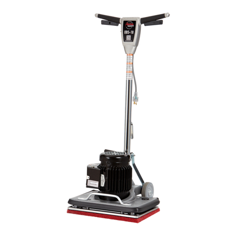
Clarke OBS-18DC Installation and operating manual

Clarke

Clarke OBS-18DC Installation and operating manual

Clarke DU-8R User manual

Clarke

Clarke DU-8R User manual

Clarke CFP-130 User manual

Clarke

Clarke CFP-130 User manual

Clarke METALWORKER CBB200E Instruction Manual

Clarke

Clarke METALWORKER CBB200E Instruction Manual

Clarke 7013A User manual

Clarke

Clarke 7013A User manual

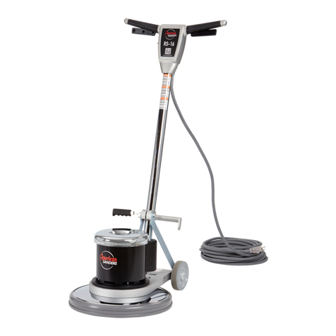
Clarke RS-16 HDTR User manual

Clarke

Clarke RS-16 HDTR User manual

Clarke CROS1 Installation and operation manual

Clarke

Clarke CROS1 Installation and operation manual

Clarke C2K-1600HD User manual

Clarke

Clarke C2K-1600HD User manual

Clarke 07101B User manual

Clarke

Clarke 07101B User manual

Clarke EZ Sand Installation and user guide

Clarke

Clarke EZ Sand Installation and user guide

Clarke CONTRACTOR CON320 Instruction Manual

Clarke

Clarke CONTRACTOR CON320 Instruction Manual

Clarke CDS1V Instruction Manual

Clarke

Clarke CDS1V Instruction Manual

Clarke RS-16 HDTR Installation and operating manual

Clarke

Clarke RS-16 HDTR Installation and operating manual

Clarke Woodworker CS6-9C Installation and operation manual

Clarke

Clarke Woodworker CS6-9C Installation and operation manual

Popular Sander manuals by other brands

Dynabrade 51830 user manual

Dynabrade

Dynabrade 51830 user manual

FXA FXAJD2523 instruction manual

FXA

FXA FXAJD2523 instruction manual

Grizzly T33256 owner's manual

Grizzly

Grizzly T33256 owner's manual

Silverline 631320 User instructions

Silverline

Silverline 631320 User instructions

Black & Decker 7041 instruction manual

Black & Decker

Black & Decker 7041 instruction manual

DeWalt D26441 instruction manual

DeWalt

DeWalt D26441 instruction manual

OMCA SMR 930 Handbook

OMCA

OMCA SMR 930 Handbook

Schleifhexe BS 200 Original instructions

Schleifhexe

Schleifhexe BS 200 Original instructions

Ryobi RPS80 Original instructions

Ryobi

Ryobi RPS80 Original instructions

Oliver 6305 owner's manual

Oliver

Oliver 6305 owner's manual

Jet 22-44 Pro-3 Operating instructions and parts manual

Jet

Jet 22-44 Pro-3 Operating instructions and parts manual

Workzone 47561 user guide

Workzone

Workzone 47561 user guide

Makita M9204 technical information

Makita

Makita M9204 technical information

Makita M9204 instruction manual

Makita

Makita M9204 instruction manual

Chicago Pneumatic CP9778 Operator's manual

Chicago Pneumatic

Chicago Pneumatic CP9778 Operator's manual

Ferm FEOS-135 user manual

Ferm

Ferm FEOS-135 user manual

Unior 1510 Operating	 instruction

Unior

Unior 1510 Operating instruction

stayer ls1200 operating instructions

stayer

stayer ls1200 operating instructions

manuals.online logo
manuals.online logoBrands
  • About & Mission
  • Contact us
  • Privacy Policy
  • Terms and Conditions

Copyright 2025 Manuals.Online. All Rights Reserved.

56043143 Page 1
MODELS: 07097A, 07127A, 07128A
56043143 Page 2
Switch Replacement
1-Remove the two screws (13) securing the right handle (42)
2-Remove switch retaining nut (68)
3-Pull switch from handle (Fig. 25)
4-Remove tape from switch to expose wiring connections
5-Disconnect all wires from switch
Assembly Hints
Connect the light wires with the incoming power wires on the switch so that
the light is on when machine is plugged in
Always retape the switch to prevent shorting between metal objects inside
machine
Switch and on/off plate are indexed for proper orientation and should be
installed with the off position to the back
Pigtail Replacement
1-Remove the two screws (13) securing the right handle (42)
2-Disconnect the black and white pigtail wires from the switch and the ground wire (52) from the handle housing
3-Remove pigtail and strain relief assembly (9) from Handle housing
Assembly Hints
Always retape the switch to prevent shorting between metal objects inside machine
Motor Brush Replacement
1-Remove the screw (7) retaining the top cover (25)
2-Disconnect wires from field to brushes
4-Remove the two screws (53) securing each brush holder assembly (56)
5-Push the holder down and over to remove it from the field housing (Fig. 26)
6-Disconnect shunt wire and pull brush (59) out toward the brush side
Speed selection switch replacement
1-Remove four screws (6) securing the cover (19)
2-Remove the switch retaining nut (36)
3-Disconnect wires from switch
Assembly Hints
Black wire from field and diode ground wire connect to the Hi side of switch and the White wire from the field and the diode
terminal wire connect to the Lo side
Diode Replacement
1-Remove four screws (4) securing the field housing (28)
2- Remove field housing assembly by holding the handles and gently tapping down on the lower housing
3-Remove the diode securing nut (33) from inside the housing (Fig. 27)
Assembly Hints
Insulating washers (32) must be intact and installed on both sides of the field housing. The dust baffles can be retained with
super glue to keep them in place while reinstalling the field housing assembly if they were loosened during disassembly.
Fig. 25
Fig. 26
Fig. 27
56043143 Page 3
56043143 Page 4
Pad Removal and Replacement
1-Remove paper retaining bolt (37)
2-Wedge dust fan with screwdriver or similar object
3-Use spanner wrench (Fig. 28) or punch and hammer (Fig. 29) to remove pad
Note: When replacing the old style steel pad with the new style aluminum the fiber washers between the
pad and lower bearing must be discarded.
Gearbox Removal and Repair
1-Remove pad (35)
2-Remove wall guard
3-Remove three screws (31) from gear cover (29)
4-Press jackshaft (23), gear (22) and bearing (20) assembly out of the cover using the paper retaining
screw to prevent damage to the shaft
5-Remove retaining ring (20) and press the jackshaft out of the gear and bearing
6-Remove retaining ring (25) and press bearing out of the cover
Reassembly
1-Press bearing (27) in cover using outer race only
2-Install seal (26) and Retaining ring (25)
3-Install key (24) and press gear (22) on jackshaft
4-Press bearing (21) on jackshaft using the inner race only
5-Install retaining ring (20)
6-Press the jackshaft assembly into the cover assembly by pressing on the upper end of the jackshaft
while supporting the inner race of the cover bearing
Pinion Gear Removal
1-Remove four screws (4) securing the field housing assembly
2- Remove field housing assembly by holding the handles and gently tapping down on the lower housing
(8)
3-Remove the dust baffles (72)
4-Pry the armature assembly up and out of the lower housing (Fig. 30)
5-Remove retaining ring (78)
6- Use gear puller to remove bearing (76) and pinion gear (77) from armature
Reassembly
NOTE: Lower gearbox assembly must be removed when reinstalling the pinion
1-Press bearing (76) and seal (75) in lower housing (8)
2-Press armature into the lower housing assembly
3-Install key (74)
4-Press pinion gear on armature
5-Reinstall the lower gear housing assembly
Armature Replacement
1-Remove four screws (4) securing the field housing assembly
2- Remove field housing assembly by holding the handles and gently tapping down on the lower housing
(8)
3-Remove the dust baffles (72)
4-Pry the armature assembly up and out of the lower housing (Fig. 30)
5-Remove pinion gear (77) and bearing (76)
56043143 Page 5
Reassembly
1-Press uper bearing (71) on armature using the inner race only
2-Press bearing (76) and seal (75) in lower housing (8)
3-Press armature into the lower housing assembly
4-Reinstall pinion gear
5-Reinstall dust baffles
6-Reinstall the field housing assembly
Assembly Hints
Pinion and drive gears should always be replaced as sets
It is recommended that the upper and lower armature bearings be replace when installing a new armature
The dust baffles can be retained with super glue to keep them in place while reinstalling the field housing
assembly.
Fig. 28
Fig. 29
Fig. 30
56043143 Page 6
Symptom
Cause
Repair
Sander will not
turn on
No power at outlet
Check and repair power supply or move to
another outlet
Defective cord or plug
Check continuity and replace defective part
Defective switch
Replace switch
Broken wire or bad connection
on brush holder assembly
Repair or replace brush holder assembly
Extremely worn motor brushes
Replace brushes
Defective armature
Replace armature
Excessive arcing
at motor brushes
Brushes worn
Replace brushes
Broken wire or bad connection
on brush holder assembly
Repair or replace brush holder assembly
Worn or defective armature
Replace armature
Sander bounces
on floor when
sanding
Bent or damaged sanding pad
Dress or replace pad
Poor dust pick-up
Dust bag is over 1/3 full
Empty bag
Dust bag is dirty
Shake debris from bag and wash or replace bag
Obstruction in dust tube
Clear dust tube
Castors adjusted improperly
Adjust castors
Sander continues
to run in low speed
when switched to
high
Two speed switch is defective
Replace switch
Sander continues
to run in high
speed when
switched to low
Two speed switch is defective
Replace switch
Diode is defective
Replace diode
A Nilfisk-Advance Brand
14600 21st Avenue North
Plymouth, MN 55447-3408
www.clarkeus.com
Phone: 800-253-0367
Fax: 800-825-2753
©2010 Nilfisk-Advance, Inc.