Class 1 Twister Installation guide

– CAN Electronic Throttle
OEM Quick Manual
Twister
™
(CAN) OEM Quick Manual P/N 120318
REV C
9-7-2010
INSTALLATION
Mount the Twister™(p/n 119970) on the operator’s panel with four
#6 screws and nuts. The dimensions in the detail below are in
inches [millimeters].
WIRING
The Twister has a single six (6) pin Deutsch connector. The mating
connector is a DT06-6S.
IDLE BUTTON OPERATION
The Twister’s IDLE button is used to set the engine RPM back to
idle (and enter passwords for configuration).
Press and hold the IDLE button for a half second and the engine
ramps down to the configured idle RPM. The ACTIVE LED remains
ON while the Twister ramps the engine to idle and then it turns OFF.
CONTROL KNOB OPERATION
The Twister’s control knob is used to control engine RPM (and enter
passwords for configuration).
The “increase RPM" direction of the control knob can be configured
for clockwise or counter-clockwise rotation (clockwise is default).
Each tactile click of the control knob equals 5 RPM.
LED OPERATION
The Twister has two (2) LEDs located on its front panel on either side
of the control knob.
Throttle Ready LED:
The green THROTTLE READY LED is ON when the Twister’s
interlock (pin 3) is active. This indicates that the Twister is
transmitting J1939 engine control commands and is ready for
operator initiated control via the control knob.
The THROTTLE READY LED flashes when the Twister is not
receiving engine RPM data from the J1939 CAN bus. No throttle
control is permitted when the THROTTLE READY LED is flashing.
Active LED:
The blue ACTIVE LED is ON when the Twister’s knob has been
turned in the increase RPM direction. This LED indicates the Twister
is actively controlling the engine.
The ACTIVE LED flashes when the operator is rotating the control
knob while the engine RPM is at the configured maximum RPM.
ENTERING PASSWORDS
The Twister utilizes passwords to modify its operational parameters.
All operational parameters are stored in memory and will not be lost
when power is disconnected.
To enter a password:
Press and hold the IDLE button until the ACTIVE LED blinks
twice (two seconds). Continue holding the IDLE button while
entering the password.
Each clockwise rotation will turn the ACTIVE LED ON for a
half- second and each counter-clockwise rotation will turn
the THROTTLE READY LED ON for a half-second.
Wait for the LED indication to turn OFF before rotating the
knob again.
If an error is made while entering a password, release the IDLE
button to clear and then re-attempt the password from the beginning.
ENGINE TYPE CONFIGURATION
The Twister must be configured to transmit the J1939 CAN
communication data required for the particular engine type. The
Twister’s default communication data method is via the
Torque/Speed Control 1 (TSC1) PGN 0 CAN message, but
Cummins Fire Pump Governor (CFPG) or Scania methods may be
selected.
TSC1 communication method (default):
CFPG communication method:
Scania communication method:
KNOB ROTATION CONFIGURATION
The Twister allows the knob rotation direction for increase RPM to
be configured. The default is clockwise rotation yields an increase
in engine RPM. But this may be changed to counter-clockwise
rotation yields an increase in engine RPM by entering a password.
Clockwise rotation equals increase engine RPM (default):
Counter-clockwise rotation equals increase engine RPM:
INTERLOCKING
The interlock input (pin 3) must be active before the Twister will
allow control of the engine’s RPM.
It is the OEM’s responsibility to create a safe interlocking scheme to
activate the Twister’s interlock input.
The Twister’s green THROTTLE READY LED will ON when the
interlock input is active. The Twister is now ready for operator
initiated control.
The Twister allows configuration of the interlock input’s (pin 3)
activation polarity (positive voltage or ground).
Positive polarity interlock configuration password (default):
Ground polarity interlock configuration password:
ENGINE RPM RANGE CONFIGURATION
The Twister allows configuration of its idle RPM and maximum
RPM values. The defaults are 800 RPM idle, 2200 RPM
maximum.
Idle RPM configuration:
Enter the password -
Release the IDLE button.
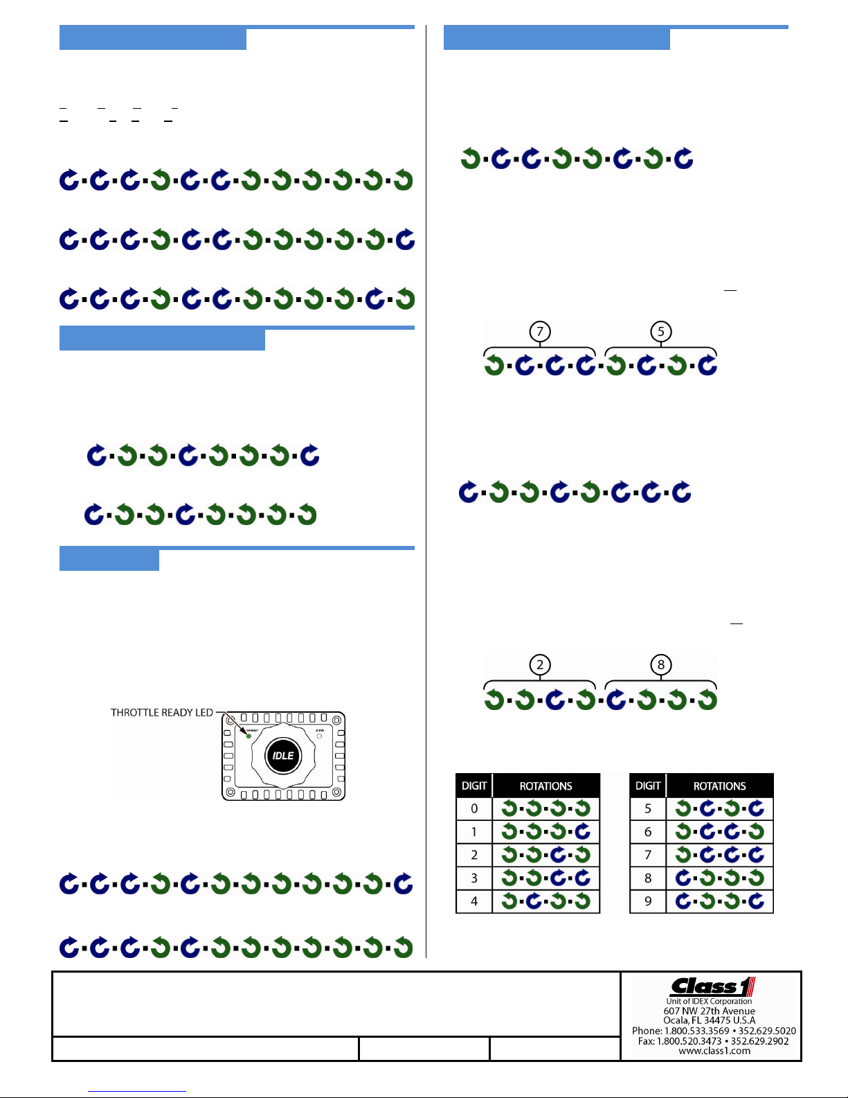
The idle RPM value is entered by using a password created from the
hundreds and tens digits of the desired idle RPM value. Use the
DIGIT/ROTATIONS chart below to select the knob rotations for the
two digits of the password. The valid range is 50 (500 RPM) to 95
(950 RPM).
For example, 750 RPM would use the numbers 7 and 5 (750).
The password for 750 RPM is –
Press the IDLE button to clear the RPM password if a mistake has
been made.
Maximum RPM configuration:
Enter the password -
Release the IDLE button.
The maximum RPM value is entered by using a password created
from the thousands and hundreds digits of the desired maximum
RPM value. Use the DIGIT/ROTATIONS chart below to select the
knob rotations for the two digits of the password. The valid range is
15 (1500 RPM) to 45 (4500 RPM).
For example, 2800 RPM would use the numbers 2 and 8 (2800).
The password for 2800 RPM is –
Press the IDLE button to clear the RPM password if a mistake has
been made.
For detailed operation and troubleshooting consult the full manual (p/n 120477) available from the Class 1
Twister (CAN) OEM Quick Manual P/N 120318 REV C 9-7-2010
Popular Automobile Accessories manuals by other brands


Phoenix Gold
Phoenix Gold Stinger TXJWB12 installation guide

ELSECSYS
ELSECSYS CPPRO user manual

Metra Electronics
Metra Electronics 99-7011 installation instructions

Juice
Juice Booster 2 user manual

Whelen Engineering Company
Whelen Engineering Company LC Series installation guide

VBG
VBG Onspot Mounting instructions