© 2019
Step 1 of 1
Order #XXXXX
7
7
6
6A
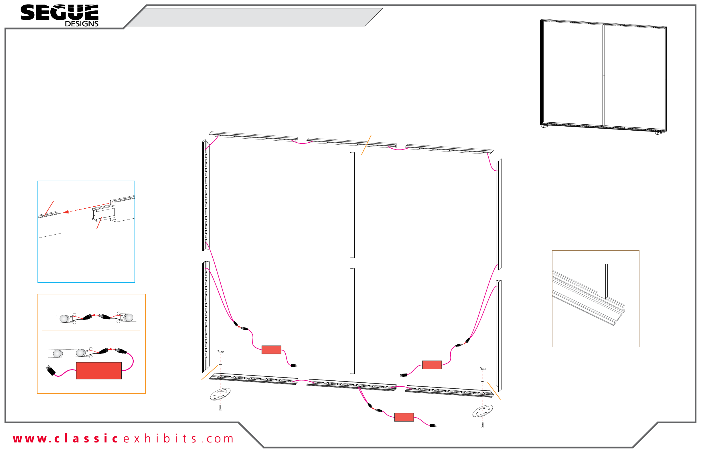
Completed Assembly
Power
Break
Power
Break
Power
Break
to power
to power
*
*
to power
*
++
+
-
-
-
Lights
Male
Male
Female
Female
to power Transformer
144W / 6A / 24V
Light to Light Connection
Light to Transformer Connection
Maximum of 11 light bars per transformer.
Z45 Straight Connection
*
PR53
Connector
Z45 Z45
Insert connector into extrusions.
Secure with set screws.
Set Screw
To prevent product loss, keep all
screws attached to connector
after disassembling.
CEI-110
Z45
Z45 Attachment
Attach Z45 vertical to back
groove of CEI-110 horizontal.
*
F
r
o
n
t
of
F
r
a
m
e
1
4
4A
5
5A
3
1A 2A
2
3A
Steps:
1) Assemble CEI110 extrusions together, flat on floor, as shown. See CEI110 Frame
Assembly sheet for instruction.
2) Attach base plates [7] to horizontals [1] and [3], using bolts, washers, and nuts, then
lift assembled frame upright.
3) Connect verticals [6] and [6A] together. See Z45 Straight Connection detail.
4) Attach [6/6A] assembly to center of assembled CEI110 frame. See Z45 Attachment detail.
5) Connect light cords and transformers. See Light Connection and details.
6) Attach graphic to front of assembled frame. See SEG Graphic Installation sheet for details.
Item
1,1A
2,2A
3,3A
4,4A
5,5A
6,6A
7
Qty.
2
1,1
1,1
1,1
1,1
1,1
2
Description
38” CEI110 Horizontal Extrusion
38” CEI110 Horizontal Extrusion
38” CEI110 Horizontal Extrusion
47.5” CEI110 Vertical Extrusion
47.5” CEI110 Vertical Extrusion
45.6767” Z45 Vertical Extrusion
Base Plate
Keep PR53 connector attached
to extrusion [6], when packing.
FRONT VIEW
VK-1968 Supernova Assembly